Bielas que varian su longitud para conseguir mejoras de hasta el 7% en consumo

Los motores de relación de compresión variable sigue suponiendo uno de los grandes retos de la industria en lo que a beneficios ofrece y complicaciones de diseño sugiere. Variar la relación de compresión en cada uno de los cilindros permite contar con un ciclo de trabajo adaptado a cada circunstancia, permitiendo adaptar el propulsor para otorgar altas dosis de potencia o reducidos consumos de carburante.

Marcas como SAAB o Peugeot han mostrado al público prototipos que buscaban dotar a los propulsores gasolina de esta posibilidad de variar la relación de compresión bajo demanda, pero sus elevados costes y complejidad técnica han alejado a esta tecnología del mercado. Ingenieros de FEV han mostrado su último desarrollo donde el diseño de una biela convencional ha sido adaptado para permitir variar la relación de compresión garantizando dos estados diferentes donde encontrar máxima eficiencia y máxima entrega de prestaciones.

Relación de compresión variable

Bielas que varian su longitud para conseguir mejoras de hasta el 7% en consumo

El concepto de relación de compresión variable es uno de las grandes frentes de la industria para mejorar el motor de combustión interna

El diseño mostrado por FEV hace gala de un mecanismo que, mediante el empleo de un circuito de aceite a presión, permite modificar la altura de la cabeza del pistón respecto de la cámara de combustión. Modificando esta distancia, se consigue variar la relación de compresión entre dos valores fijos establecidos.

Uno de las claves de este diseño implementado por FEV es la búsqueda de una solución que permita un funcionamiento sin alterar lo que se podría entender como estructura clásica de un motor de combustión interna. Huelga a decir que la complejidad técnica y elevados costes son el principal enemigo de esta tecnología. De este modo, FEV ha rediseñado la clásica biela que une pistón y cigüeñal para configurarla de tal modo que permita la modificación de la alzada del pistón en el interior del cilindro.

Bielas que varian su longitud para conseguir mejoras de hasta el 7% en consumo

En un motor gasolina donde la relación de compresión estaba situada en 9,6, FEV ha instalado su sistema de relación de compresión variable permitiendo un margen de entre 8 y 13. Con esta configuración y bajo ciclo de homologación NEDC, el consumo se ha reducido en un 5,6%. A su vez, aplicando este diseño de relación de compresión variable a mecánicas muy compactas fruto del downsizing, FEV establece que la reducción en consumo podría alcanzar el 7%.

Fuente: GreenCarCongress | FEV | Diariomotor

¿Cuáles son los componentes principales y la función de las válvulas?

VALVE TRAIN: COMPONENTS, TYPES AND THEIR FUNCTION

No photo description available.

The main function of the valve train, as indicated by its name, is to control the opening and closing of the valves and, for older models, the fuel output of the injectors. Most of the heavy-duty diesel engines we work with are 4 valve engines, meaning there are four valves in each cylinder: 2 intakes and 2 exhaust. The valve train uses different components based on the type, push on or lift up from the valves, allowing air into and out from the cylinder. In the middle of all the valves is the injector, which will be pushed down on to inject fuel into the cylinder. All of the timing for this process is incredibly precise. Newer engines use electrical signals to cue the injector, rather than the mechanical valve train, which makes that process even more precise.

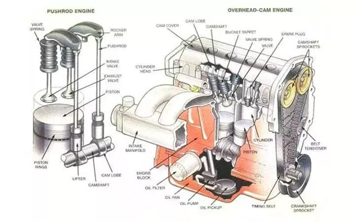
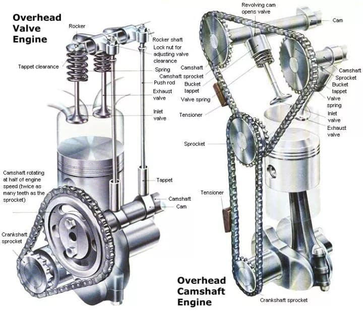
Most new engines have overhead cam assemblies. Other designs locate the camshaft lower in the engine and use push rods to move valve assemblies. The camshaft is rotated by a timing belt, timing chain or direct gear.

VALVE TRAIN COMPONENTS

The valve train can have many components. The following are the most common components in the valve train. Depending on the type of engine, there may be varying quantities of the parts listed below or the engine may not contain all of the parts listed.

1. Camshaft
The camshaft is a long shaft that goes through the head or the block of the engine, depending on what type of engine it is. There are lobes along the length of the shaft positioned differently. The profile of the lobes has an egg-shape to them. The dimensions of these lobes are what determines the amount of lift. The more lift, the longer the valves stay open, which allows more air into the cylinder.

2. Camshaft Followers
A cam follower is a type of bearing that follows along the lobes of a camshaft as it rotates, providing a low-resistance surface for the lobe to push up against. A follower is also called a lifter, and sometimes a tappet. There are several types of cam followers, whose configurations generally depend on how they mount to their mating part. They will be used when the cam is in the block, rather than being overhead.

No photo description available.

3. Push Rods
Pushrods are one of those parts that are not always used in a diesel engine. They will also only be used when the cam is in the block and not overhead. A push rod is a rod that pushes up on the rocker arm. It will move depending on the movement of the camshaft follower. Another job of the pushrod is to conduct oil up to the cylinder head.

4. Rocker Arms
A rocker arm is a pivoting lever that pushes on the valve stem. Rocker arms will sometimes be called rocker levers, or just rockers. Depending on the type of valve train, the rotating camshaft lobes will either push directly on the rocker arm, or on the pushrods, which will conduct the motion up to the rocker arm. In an overhead cam engine, the cam follower is built into the rocker arm in the form of a roller.

5. Rocker Shafts
Rocker shafts are simply the shafts that the rockers are on. It’s this shaft that is the pivot point for the rocker arms. The shaft also conducts oil to the various rocker arms.

6. Valve Bridges
Valve bridges are also sometimes called valve yokes. Bridges allow a single rocker to actuate multiple valves. It has a stem or bridge that sits on both valve stems, so that when the rocker is pressed down, the valve stems get pressed down as well.

7. Valves
A valve is composed of two major sections, the valve head, and the valve stem. The head of the valve is what allows air into and out of the cylinder. The stem is what gets pressed on by the rest of the valve train. At the end of the stem are grooves that keepers will fit into to hold the valve in place. Some engines have only two valves per cylinder, and some have four. The more common number in the heavy-duty diesel market is four. These are split evenly between the intake and exhaust valves.

8. Valve Springs
The camshaft creates an upward force that acts on the rocker arm, which in turn pushes the valve down. But as the cam rotates around, it does not pull the pushrod or rocker arm back with it. That’s why there is a valve spring to create force in the opposite direction and close the valve. The spring will hold the valve closed until the lobe of the camshaft comes around with a greater force and pushes it down.

9. Timing Belt:
A timing belt instead of a timing chain may be used to turn the camshafts. The inner side of the belt is designed with square (cogged) teeth which prevent the belt from slipping.

10. Belt Tensioner
The belt tensioner is a spring-loaded wheel which keeps the timing belt in tension and aligned with the cam sprocket. The smooth side of the timing belt rides over the tensioner. The tensioner applies a force on the backside of the belt. This keeps the belt in tension. Whenever the belt needs to be removed, the tensioner can be pulled away, freeing the belt.

TYPES OF VALVE TRAINS

1. OHV or Push-rod valve train

In case of OHV or push-rod systems, there are long rods which have to be pushed by the camshaft lobes to move the valve rockers, which in turn open the valves – thus the name ‘push-rod’. The long rods and the mechanical nature of the pushrod system make it heavy and it’s not compatible with engines which run at higher revolutions per minute. Now while OHV is an older design, it has its advantages in terms of simplicity of design, compact packaging and a simpler lubrication system requirement as compared to an OHC system.
The disadvantages, of a pushrod system, however, are many.
• To start with, the engines with an OHV system cannot run very high RPMs and such valve trains are suitable mostly for low engine speed applications such as heavy cruisers.
• Owing to the heavy components, the noise and friction on such systems are much more than an OHC system.
• Also, any issues with the camshaft require the entire engine to be opened up, as the camshaft sits inside the engine block, which increases the maintenance effort and cost in case of a breakdown.
• Finally, OHV engines lend their design well primarily to two-valves per cylinder layout. It’s not that there aren’t any three or four valves per cylinder engines with OHV, but that setup becomes way more complex, and OHC systems offer much more flexibility with multiple valves per cylinders.

No photo description available.

2. OHC Valve trains

To overcome the shortcomings of the pushrod valve trains, OHC valve train was developed. As the name suggests, it’s a valve train configuration where the camshaft for the engine is placed over the head of the engine, above the pistons and valves. This design allows for very direct contact between the camshaft lobes and the valves or a lifter, thus reducing mass, reducing components and allowing better engine performance as well as more flexibility with the overall engine design.

A. Single Overhead Cam/SOHC

For this variety of valve trains, there is a single camshaft for each row of engine heads. So a single cylinder OHC engine will have one camshaft. However, if it’s an engine with multiple rows, say a V6, then it will have two camshafts – one for each row of heads, or each bank. For SOHC engines, the camshaft is connected directly to the crankshaft via a timing belt or chain to ensure that the opening and closing of the valves is perfectly in sync with the various strokes of the engine for each cylinder.

Now, with SOHC, there is an option to either open or close the valves directly with a shim between the cam lobe and the valve stem, or via a rocker arm. Valves have springs which return them back to their closed position once the pressure from the camshaft lobe is off. SOHC engines are also suited better for 2 or 3 valves per cylinder configuration. Not that a SOHC valve train cannot run on a 4 valve per cylinder layout, but the whole set-up then becomes too complex for the design of rocker arms and lobes and it’s generally considered better to employ a DOHC valve train is such scenarios.

B. Double Overhead Cam/DOHC

DOHC or dual overhead camshaft design includes two camshafts for every row of cylinder heads. Talking about the example we took for SOHC, a DOHC setup for a single-cylinder engine will have two camshafts. However, if it’s a V6, it will have 4 camshafts, two for each row of engine heads, or banks. The primary advantage of such a setup is that it allows manufacturers to have a well-engineered answer to handling a 4-valves per cylinder. Generally, one of the camshafts handles the intake valves, while the second one handles the exhaust valves. The 4-valve per cylinder setup allows for better breathing for the engine, and better performance in most cases, making DOHC a choice for engines that need to rev higher. A DOHC setup also allows for putting the spark plug bang in the middle of the cylinder head, which facilitates better combustion, and enhances performance, and fuel efficiency of the engine. With SOHC, such a setup is not possible for 4-valves per head, as it has to sit in the middle of the cylinder head so as to operate both intake and exhaust valves. As mentioned before, though, SOHC engines too can handle four valves per cylinder, and while the construction of such valve trains is complex, it’s desirable in some cases. DOHC brings along the extra weight of the additional cam, though by allowing the positioning of the spark plug in the middle of the cylinder head it also enhances optimum combustion of fuel. In a nutshell, DOHC is more suited for high-performance engines which need to rev higher and perform in the higher rev range. SOHC systems have somewhat better lower end torque though.

Finally, a DOHC system, with its more fine-grained control over valves is more suitable to implement variable valve timing for engines. Such systems utilize variable camshaft profiles for different engine speeds to enhance performance across the entire rev band. The control over the speed and position of valves opening and closing is better in case of DOHC, and in today’s electronics driven world, great benefits can be extracted using that fact. DOHC valve train is more expensive than SOHV though and coupled with its suitability for 4 valves per cylinder, it makes it feasible to employ that setup only on automobiles above a certain price point. For applications where everyday usability, low and mid-range torque, simplicity of design, easy construction and cost are important factors, SOHC system works well.

Automotive World

¿Qué es el Dámper en el motor del automóvil?

Resultado de imagen para damper automotriz

El dámper no es más que una polea situada en un extremo del cigüeñal. De hecho, técnicamente lo correcto es llamarla polea del cigüeñal, aunque comúnmente se la conozca como “dámper” o “polea dámper”.

Su función es parecida a la del volante bimasa, sirve para amortiguar las vibraciones del cigüeñal provocadas por la serie de explosiones que mueven los pistones

Si la polea dámper de nuestro coche se estropea lo primero que notaremos serán más vibraciones y ruidos provenientes del motor, sobre todo al ralentí. El cigüeñal sufrirá más y debido a las torsiones que el dámper no amortiguaría, podría llegar a romperse preparando una carísima avería que podría acabar mandado el coche al desguace.

Una polea dámper en mal estado también puede provocar que se salte la distribución, se rompa la correa, la bomba de la dirección o deteriore el funcionamiento del compresor de aire acondicionado. En cualquier caso, una avería cara de reparar.

Es un elemento muy sencillo, pero conviene revisarlo periódicamente por el bien de la vida útil de nuestro motor.

Cuáles son los grados mecánicos que influyen en los neumáticos?

No photo description available.

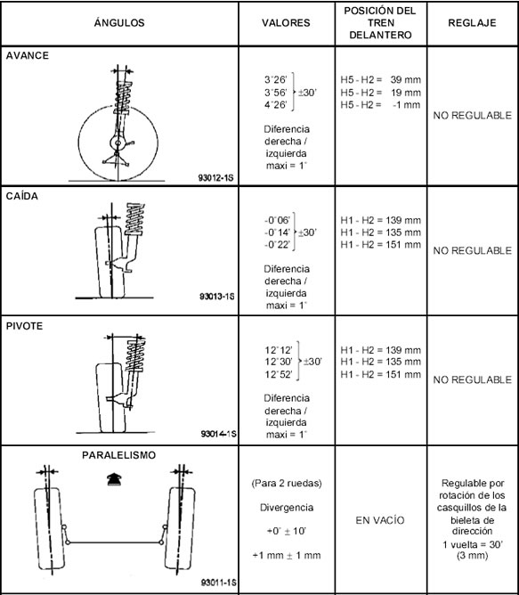
Todos los vehículos de transporte vienen con una convergencia positiva para que al estar en movimiento, las ruedas tiendan a quedar paralelas. Esto ocurre porque el eje delantero, al ser empujado, permite una abertura de las ruedas, dentro de los límites de operación de los componentes de la dirección. Por lo tanto si las terminales estuvieren flojas más de lo normal tenderán a abrirse más, generando convergencia negativa.

Si el desgaste del neumático aparece a partir del hombro externo, indicará convergencia positiva en exceso.

La DIVERGENCIA significa que los bordes traseros de las llantas, ya sean del eje trasero o delantero, estarán más cerca entre sí que los bordes delanteros. La divergencia se usa comúnmente en autos de tracción delantera para contrarrestar la tendencia a converger mientras se conduce a velocidades altas. Alguna divergencia es necesaria para que los automóviles viren.

Si se tienen averías en los brazos auxiliares, estarán afectadas la convergencia y la divergencia en curvas, ambas produciendo el mismo síntoma de desgaste en los neumáticos (desgaste escamado a partir de los hombros internos, en dirección al centro de la banda de rodamiento). Esto ocurrirá porque las ruedas se abrirán más de lo necesario.

El CAMBER es el ángulo que forman por una parte una línea imaginaria de la rueda con una línea vertical y perpendicular al piso. El camber puede ser hacia dentro (camber negativo) o hacia fuera (camber positivo).

Todos los vehículos de transporte vienen con camber positivo, pues cuando el vehículo recibe su carga y es puesto en movimiento, la tendencia de las ruedas es de abrirse en la parte inferior.

Cuando el eje se desvía por sobrecarga, el camber queda negativo y el desgaste de los neumáticos se producirá a partir de los hombros internos, esto es porque las ruedas habrán quedado muy abiertas en la parte inferior.

El desgaste por camber incorrecto se acentúa en los hombros del neumático, no solo por la alteración de la distribución de peso, si no principalmente por generar dos diámetros diferentes dirigidos por el radio inferior, girando en torno al mismo eje.

Cuál es la función principal del clutch en la transmisión manual?

CLUTCH: FUNCTION, WORKING AND CLASSIFICATIONS

No photo description available.

The clutch is a mechanical device, which is used to connect a driving shaft to driven shaft so that they can be engaged and disengaged at the will of the operator. They used to start and stop a part of a system without stopping remaining parts of the power transmission system. They are used mostly in automobiles. The clutch allows to insert a gear system (gearbox) between engine and wheels, facilitate gear changing when the engine is running. Other applications of clutch: Torque limiting clutch in the electric screwdriver, bicycles pedal ratcheting.

Function of the Clutch

1. Function of transmitting the torque from the engine to the drivetrain.
2. Smoothly deliver the power from the engine to enable smooth vehicle movement.
3. Perform quietly and to reduce drive-related vibration.
4. Protect the drivetrain when given the inappropriate use. Given the situation, the Exedy clutch will fail when giventhe inappropriate use inturn to protect the rest of the drivetrain, similar to the function of an electric fuse.

Requirements of a good clutch

1. The clutch should be able to transmit 1.25 to 1.50 times the maximum engine torque.
2. The clutch material should have good coefficient of function.
3. Lot of heat is generated due to the relative motion between the flywheel, pressure plate and clutch plate during clutch operation. This heat needs to be quickly dissipated, otherwise high temperature can damage clutch components.
4. The clutch should have low moment of inertia, otherwise the clutch will keep spinning at high speed even during gear changing.
5. Vibration and Jerk absorption. The clutch should be able to take up sudden jerks encountered when the clutch plate comes in contact with the rotating flywheel.
6. The clutch should be dynamically balanced or it will lead to vibrations at high speeds.
7. The operation of the clutch pedal should be easy for the operator and not tiresome, especially for operating for long durations.

Clutch Facing Material

While selecting material for clutch facing, it is to be kept in mind that the material should have high coefficient of friction, low heat generation and quick dissipation of generated heat. These qualities are counter to each other. Hence a tradeoff has to be reached. Most common materials that can be used are as follows:
* Leather -Coefficient of friction of dry leather on iron is 0.27
* Cork -Coefficient of friction on dry steel is 0.32
* Fabric -Coefficient of friction on dry steel is 0.4, but these cannot be used at high temperature.
* Asbestos -Coefficient of friction on dry steel is 0.2, has good anti-heat properties, but is harmful for human health.
* Ferodo Material -This material is based on asbestos and has a coefficient of friction 0.35.

HOW CLUTCH WORKS

No photo description available.

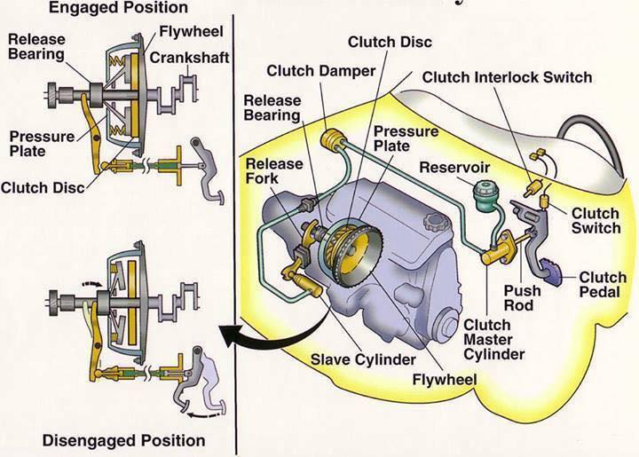
It transmits engine power to the gearbox, and allows transmission to be interrupted while a gear is selected to move off from a stationary position, or when gears are changed while the car is moving.

Most cars use a friction clutch operated either by fluid (hydraulic) or, more commonly, by a cable.

When a car is moving under power, the clutch is engaged. A pressure plate bolted to the flywheel exerts constant force, by means of a diaphragm spring, on the driven plate.

Earlier cars have a series of coil springs at the back of the pressure plate, instead of a diaphragm spring.

The driven (or friction) plate runs on a splined input shaft, through which the power is transmitted to the gearbox. The plate has friction linings, similar to brake linings, on both its faces. This allows the drive to be taken up smoothly when the clutch is engaged.

When the clutch is disengaged (pedal depressed), an arm pushes a release bearing against the centre of the diaphragm spring which releases the clamping pressure.

The outer part of the pressure plate, which has a large friction surface, then no longer clamps the driven plate to the flywheel, so the transmission of power is interrupted and gears can be changed.

Clutch engaged
The diaphragm spring is holding the driven plate.

Clutch disengaged
The release bearing has depressed the diaphragm spring.

When the clutch pedal is released, the thrust bearing is withdrawn and the diaphragm-spring load once again clamps the driven plate to the flywheel to resume the transmission of power.

Some cars have a hydraulically operated clutch. Pressure on the clutch pedal inside the car activates a piston in a master cylinder, which transmits the pressure through a fluid-filled pipe to a slave cylinder mounted on the clutch housing.

The slave-cylinder piston is connected to the clutch release arm.

CLUTCH TYPES

No photo description available.

These may classified as follow:

According to the method of transmitting torque:

1. Positive clutch (Dog clutch):
In the positive clutch, grooves are cut either into the driving member or into the driven member and some extracted parts are situated into both driving and driven member. When the driver releases clutch pedal then these extracted parts insert into grooves and both driving and driven shaft starts revolve together. When he push the clutch pedal these extracted parts come out from grooves and the engine shaft revolve itself without revolving transmission shaft.

Application of positive clutch

They have very limited use. However, they have some application where the synchronous drive is required.

Advantages and disadvantages of positive clutch

Advantages
1. They do not slip.
2. They can transmit large torque.
3. Develop no heat during engagement and disengagement because of rigid interlocking (no friction).

Disadvantages
1. Engagement of clutch cannot be possible at high speed.
2. While starting some relative motion may be required to engage.

2. Friction clutch:
In this types of clutches, friction force is used to engage and disengage the clutch. A friction plate is inserted between the driving member and the driven member of the clutch. When the driver releases the clutch pedal, the driven member and driving member of clutch, comes in contact with each other. A friction force works between these two parts. So when the driving member revolves, it makes revolve the driven member of clutch and the clutch is in engage position. This type of clutch is subdivided into four types according to the design of the clutch.

Advantages of friction clutch

No photo description available.

1. Smooth engagement and minimum shock during the engagement.
2. Friction clutch can be engaged and disengaged when the machine is running since they
have no jaw or teeth.
3. Easy to operate.
4. They are capable of transmitting partial power.
5. Friction clutch can act as a safety device. They slip when the torque exceeds a safe value,
thus safeguards the machine.
6. Frequent engagement and disengagement is possible

Requirement of good friction clutch

1. The following are considered during the design of the friction clutch.
2. The coecient of friction of contact surface should be high enough to hold the load with a minimum amount of axial force. It should not require an external force to carry the burden.
3. The moving parts of the clutch should be lightweight to minimize the inertia load at high speed.
4. Heat generated at contacting surface should dissipate rapidly.
5. It should have provision for taking up the wear of contact.
6. Guard the projecting parts by covering and provide a provision for easy repair.

Requirements of material used for friction clutch

1. The actual contact surface of the friction clutch is the friction lining. Linings are subjected to severe rubbing during a machine run. There are many factors that decide the material
for lining is viable or not. However, the lining material should have certain qualities.
2. It should have a relatively high and uniform coecient of friction under all service conditions.
3. High resistance to wear.
4. It should withstand a high compressive load.
5. It should be chemically inert, oil and moisture have no eect
on them.
6. High heat conductivity. It should rapidly dissipate the heat generated.
7. It should have excellent compactibility with cast iron facing.

A.) Cone clutch:
It is a friction type of clutch. As the name, this type of clutch consist a cone mounted on the driven member and the shape of the sides of the flywheel is also shaped as the conical. The surfaces of contact are lined with the friction lining. The cone can be engage and disengage from flywheel by the clutch pedal.

B.) Single plate clutch:
In the single plate clutch a flywheel is fixed to the engine shaft and a pressure plate is attached to the gear box shaft. This pressure plate is free to move on the spindle of the shaft. A friction plate is situated between the flywheel and pressure plate. Some springs are inserted into compressed position between these plates. When the clutch pedal releases then the pressure plate exerts a force on the friction plate due to spring action. So clutch is in engage position. When the driver pushes the clutch pedal, due to its mechanism, it serves as the disengagement of clutch.

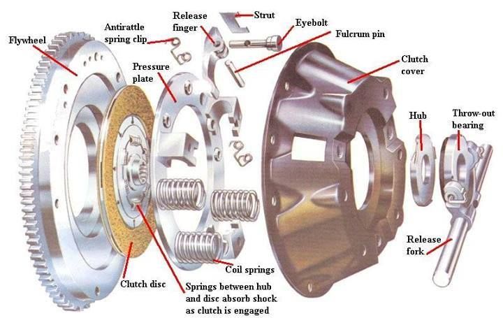
Main components of a Single Plate Axial Spring type friction clutch

1. Flywheel: It is connected to the engine crankshaft and is used to store the energy.
2. Clutch Plate: It consists of a steel disc with the centre splined. Frictional material is mounted (riveted) around the circumference of the steel disc.
3. Pressure Plate: The pressure plate pushes the clutch plate onto the flywheel due to spring pressure so that the clutch plate on one side and the flywheel on the other.
4. Axial Springs: Axial springs provide the clamping force due to which the power can be transmitted from the flywheel to the clutch plate.
5. Clutch cover:It isnot only covers the clutch components, but also provides motion from the flywheel to the pressure plate.
6. Clutch release system:it consists of those components which are required for engaging -disengaging the power transmission to the clutch plate.

C.) Multi-plate clutch:
Multi-plate clutch is same as the single plate clutch but there is two or more clutch plates are inserted between the flywheel and pressure plate. This clutch is compact then single plate clutch for same transmission of torque.

Advantages and application of dual clutch

* Torque transmission can be accomplished without interruption torque distribution to the driven road wheels. It replaces the torque converter used in conventional epicyclic-geared automatic transmissions.
* Gears shift can be done very smoothly and eortlessly
when compared to single plate automatic transmission.
* Skip gear without interruption.
* DCT is quick, Fastest gear shifting available to road car transmission. It can shift gear even faster than professional racing driver using a manual transmission.
* High eciency and Fuel economy compared to other automatic shifting.

D.) Diaphragm clutch:
This clutch is similar to the single plate clutch except diaphragm spring is used instead of coil springs for exert pressure on the pressure plate . In the coil springs, one big problem occur that these springs do not distribute the spring force uniformly. To eliminate this problem, diaphragm springs are used into clutches. This clutch is known as diaphragm clutch.

3. Hydraulic clutch:
This clutch uses hydraulic fluid to transmit the torque.

Advantages-

* More flexible as you can put it in any place
* More reliable
* Self adjust

Diasdvantages-

* Pipes can rot
* Got to use correct fluid

According to their design, this clutch is subdivided into two types.

A.) Fluid coupling:
It is a hydraulic unit that replaces a clutch in a semi or fully automatic clutch. In this type of clutch, there is no mechanical connection between driving member and driven member. A pump impeller is blotted on a driving member (Engine) and a turbine runner is bolted on the driven member (Gearbox). Both the above unit is enclosed into single housing filled with a liquid. This liquid serve as the torque transmitter from the impeller to the turbine. When the driving member starts rotating then the impeller also rotates and through the liquid outward by centrifugal action. This liquid then enters the turbine runner and exerts a force on the runner blade. This make the runner as well as the driven member rotate. The liquid flows to the runner then flows back into the pump impeller, thus complete the circuit. It is not possible to disconnect to the driving member to the driven member when the engine is running. So the fluid coupling is not suitable for ordinary gear box. It is used with automatic or semi-automatic gear box.

B.) Hydraulic torque converter:
Hydraulic torque converter is same as the electric transformer. The main purpose of the torque converter is to engage the driving member to driven member and increase the torque of driven member. In the torque converter, an impeller is bolted on the driving member, a turbine is bolted on the driven member and a stationary guide vanes are placed between these two members. This all parts are enclosed into single housing which filled with hydraulic liquid. The impeller rotates with the driven member and it through the liquid outward by centrifugal action. This liquid flowing from the impeller to turbine runner exerts a torque on the stationary guide vanes which changes the direction of liquid, thereby making possible the transformation of torque and speed. The difference of torque between impeller and turbine depends upon these stationary guide vanes. The hydraulic torque converter serves the function of clutch as well as the automatic gear box.

According to the method of engaging force:

1. Spring types clutch:
In this types of clutches, helical or diaphragm springs are used to exert a pressure force on the pressure plate to engage the clutch. These springs are situated between pressure plate and the cover. These springs are inserted into compact position into the clutch. So when it is free to move between these two members, it tends to expand. So it exert a pressure force on the pressure plate thus it brings the clutch in engage position.

2. Centrifugal clutch:
As the name implies, in the centrifugal clutch, centrifugal force is used to engage the clutch. This type of clutch does not require any clutch pedal for operating the clutch. The clutch is operated automatically depending upon the engine speed. It consist a weight pivoted on the fix member of clutch. When the engine speed increase the weight fly of due to the centrifugal force, operating the bell crank lever, which press the pressure plate. This makes the clutch engage.

3. Semi-centrifugal clutch:
One big problem occur in centrifugal clutch is that they work sufficient enough at higher speeds but at lower speed they don’t do their work sufficiently. So the need of another type of clutch occurs, which can work at higher speed as well as at lower speed. This type of clutch is known as semi-centrifugal clutch. This type of clutch uses centrifugal force as well as spring force for keeping it in engaged position. The springs are designed to transmit the torque at normal speed, while the centrifugal force assists in torque transmission at higher speeds.

4. Electro-magnetic clutch:
In the electromagnetic clutch electro-magnate is used to exert a pressure force on pressure plate to make the clutch engage. In this type of clutch, the driving plate or the driven plate is attached to the electric coil. When the electricity is provide into these coils then the plate work as the magnate and it attract another plate. So both plates join when the electricity provides and the clutch is in engage position. When the driver cut the electricity, this attraction force disappear, and the clutch is in disengage position.

According to the method of control:

1. Manual clutch:
In this type, clutch is operated manually by the driver when he need or when shifting the gear. This type of clutch uses some mechanical, hydraulic or electrical mechanism to operate the clutch. All friction clutches are include in it.
2. Automatic clutch:
These types of clutches used in modern vehicle. This clutch has self operated mechanism which control the clutch when the vehicle need. Centrifugal clutch, hydraulic torque converter and fluid coupling includes in it. This type of clutch is always used with the automatic transmission box.

Mechanical Engineering World

Cuáles son los tipos de humos que podemos encontrar en el sistema de escape?

EXHAUST SMOKE: TYPES (BLACK, WHITE, AND BLUE) AND CAUSES

Exhaust smoke is a way of your car communicating with you to say what is wrong. Usually, the smoke that gets emitted is black, white, grey and blue. The exhaust gases are an old school way to detect symptoms of problems i.e. large amounts of black smoke may mean the EGR is blocked and it’s over-fueling.
Knowing the difference between the smokes that comes from the exhaust is very useful. If you are not going to fix the car yourself, take note when the smoke appears and the color and report back to your mechanic. Avoiding the problem will only shorten the life of the engine and result in unnecessary repair bills.

TYPES OF EXHAUST SMOKES

1. White smoke
2. Black smoke 
3. Blue smoke

1. WHITE SMOKE

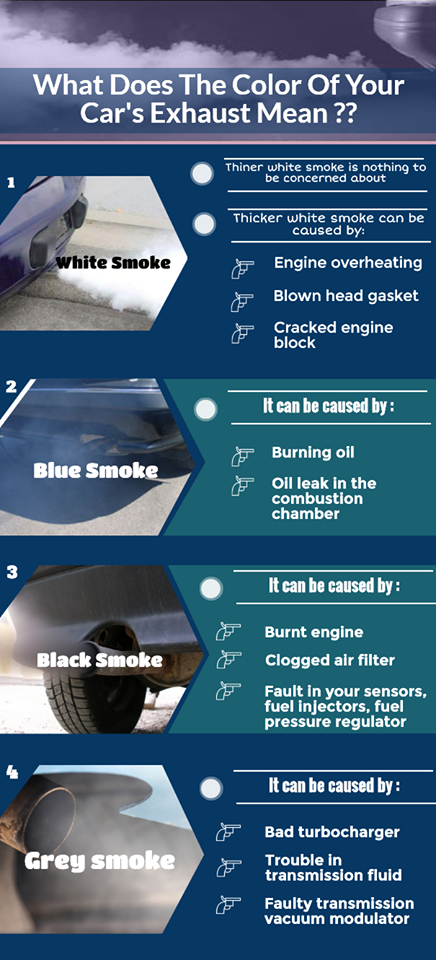
Thick white smoke can be caused by the engine burning coolant. This can be caused by the coolant leaking into the engine due to a leak in the head gasket, a damaged cylinder head or a cracked engine block. If you happen to see this kind of smoke take your car to the garage as soon as possible as the leaking coolant can lead to overheating which could cause damage to your engine. Not to mention chances of coolant mixing with the oil.
White smoke has a varying amount of causes and symptoms, which are more common in gasoline cars. The most common cause of white smoke is when the car has just been started. The white smoke is just steam from condensation that clears as the car warms up.

White Smoke from Petrol/Gasoline Car

White smoke as mentioned is usual from startup however if it continues when warm, you have a problem. Check the following for white smoke causes in petrol cars:

1. Head Gasket Failure.

A common issue with cars that have been neglected or simply the gasket has reached the end of its lifespan. Try using a head gasket sealer and testing to see if any smoke appears and you would have located the issue.

2. Turbo Issues

The turbo usually emits white or grey smoke that mostly appears under acceleration. Not as common but seals and pumps do fail and turbos problems get worse with old age.

3. Overheating Engine.

In some cases, certain engines tend to bellow out white smoke when they are too hot. Check the temperature next time there is white smoke. If it is overheating, look into potential causes, such as broken fans or no water.

4. Cracked Engine Block.

Not that common but a cracked engine block will force white smoke to the exhaust. This sort of damage to the block can cause a car to become written off by the insurance companies.

White Smoke from Diesel Car

Sadly, white smoke from a diesel car operating at its optimum temperature is bad news in most cases. Check for the following for white smoke in diesel cars:

1. Worn or Leaking Injectors.

The seals on the fuel injectors are prone to breaking down and eventually leak. This can cause a blueish/white smoke to bellow from the exhaust. Take a look on your engine bay to see if there are any signs of leakage, usually in the form of black carbon build-up.

2. Poor Quality Diesel.

Often poor quality fuel can cause a blueish mix of white smoke to emit from the exhaust. It’s always best to use high-quality injector cleaner to treat your diesel fuel.

3. Low Cylinder Compression.

Usually caused by other components such as piston rings becoming worn out

2. BLACK SMOKE

Black smoke that gets emitted from a car is more common in diesel cars. Apart from when the car is cold, white smoke should never appear from a diesel car exhaust. The majority of older diesel cars will bellow black smoke under heavy acceleration but new diesel engines will not emit any black smoke.

Black Smoke from Petrol/Gasoline Car

Black smoke in petrol/gasoline cars will is often the result of a rich mixture from the distributor. This will result in very poor miles per gallon and extra stress on engine components.

1. Rich Mixture.

A rich fuel mixture or air mixture will cause black smoke under acceleration or revving. This can be a result of a distributor unit providing too much fuel to the injectors or not enough air getting to the fuel. Some cars are tuned to run rich such as the Mitsubishi Evo.

2. Not Enough Air.

A clogged air filter or not enough air getting to the intake system completely offset the air to fuel ratio.
Petrol engines very rarely emit black smoke from the exhaust compared with diesel cars. In almost all circumstances, black smoke from a petrol car is due to the air to fuel ratio.

Black smoke from a diesel car

Black smoke from a diesel car is the result of poor combustion of the fuel. In my experience, the issue is either due to insufficient airflow or poor quality diesel that builds up into a carbon deposit. Causes of black smokes from diesel car exhausts are the following:

1. Clogged Air Filters

With dust blocking the air filter, there are chances that sufficient air amount is not reaching the cylinder. As a result, more fuel is being burnt. And, ultimately this causes black smoke from exhaust irrespective of the fact that the fuel injectors are working properly.
Besides this, due to the heavy load or during hard acceleration also black smoke can be found, as the fuel is not injected at the right time.

2. Damaged Fuel Injectors

In case of the good fuel injector, the fuel is properly atomized, which means the fine droplets of fuel are spreading equally in the cylinder. However, if the injectors don’t close on time or they are clogged, there are chances that more fuel is injected in a certain area called a rich mixture area of the car. In this situation, even the amount of air is insufficient for the combustion of fuel due to blocked injectors (and the few opened ones inject only fuel).
As a result, solid carbon is formed from the fuel not burnt, which is emitted as black smoke from the tailpipe of the car.

3. Faulty MAF Sensors

The work of the Mass Airflow sensor is to determine the volume of air entering the engine, which in turn, helps in measuring the amount of fuel to be injected inside the cylinder. This entire functioning is important for the complete combustion of fuel in the engine. Otherwise, a malfunctioning MAF sensor can lead to poor performing engine.

4. Bad EGR Valve

The EGR reduces the emission of nitrogen oxides by a re-circulating portion of an engine’s exhaust gas to the internal combustion engine. If this component is damaged, it emits all the black smoke out of the exhaust.

5. Damaged Piston Rings

One possible reason behind black smoke from the exhaust pipe is damaged piston rings. Piston Rings are designed to prevent the infiltration of engine oil inside the combustion chamber. If there is any problem with the piston rings, the engine oil starts flowing into the combustion chamber. The combustion of the mixture of this engine oil and the fuel delivers black smoke.

6. Engine Deposits

Engine deposits are another reason causing black smoke from the tailpipe. When the engine is new, it will run fluently without any problems. But after a long period of use, the engine conditions get worse and worse and this consists of getting accumulations of combustion product in important areas like combustion chambers and injectors. And these interfere with the best functioning.

7. Poor Quality Diesel Fuel.

Poor quality fuel will also cause black smoke (as well as white) to come from the exhaust. Using a diesel additive to clean vital components can fix this problem, which we recommend to do on a full tank basis.

8. Faulty Turbocharger and Bad Air to Fuel Ratio.

Diesel fuel requires an adequate air ratio in order to perform as it should from the factory. The poor ratio is usually caused through a faulty turbo, dirty/old air filter and sensors that control airflow. With bad air to fuel ratio, performance will be reduced significantly.

9. Over Fueling or ECU Chip/Tuning/Remap.

The term basically means that too much diesel is being pumped from the fuel pump. This has the potential to crack a cylinder head if it’s over fueling excessively. However, if the diesel car has been tuned or remapped, over-fueling (and over boosting) is common. I had a 1.9 TDi that was remapped, which would leave a black smokescreen in my rear mirror under heavy acceleration.

3. BLUE SMOKE

Blue smoke is an indication that the car is burning engine oil. This happens when the piston rings are worn out and oil is leaking to the combustion chamber where it is burned together with the fuel. For a turbocharged car, the smoke is a sign that the blower is in need of replacement. Burning oil can cause rough starts due to the fact that it can ruin a car’s spark plugs.

1. Stuck PVC Valve

If you observe blue smoke appearing in your car all the time, PCV (Positive Crankcase Ventilation) Valve will be the first thing you should check. The function of the PCV valve is releasing the pressure (which builds up in the Oil Pan) into the Intake Manifold (where the engine gets its air for running). The Intake Manifold is linked to the Air Filter of your engine too. So if the PCV Valve gets stuck, it will keep mixing the oil with air and other gases inside the engine. The combustion of this mixture will cause blue smoke.

2. Worn Engine

The worn engine is another culprit responsible for blue smoke from the exhaust.
Each engine has pistons which are moved up and down a cylinder. Each piston has metal rings around its side like bracelets. The function of these rings is to help the piston forming a tight seal against the cylinder. So if the rings or cylinder is worn out, oil from below the piston will come up. Then the oil gets mixed with the Air and Gasoline and gets burnt, causing the blue smoke.

3. Blown Turbo

Blown turbo is a probable reason causing blue smoke in cars that have Turbos. Blue smoke will suddenly appear in a big cloud if your car blows a Turbo. A blown turbo is either the turbo casing has damaged or a broken oil seal in the Turbo. In both cases, they let oil into the intake of the engine.

4. Blue Smoke Comes With Transmission Fluid Loss

A modulator is used to control the transmission shift in older vehicles with vacuum controlled automatic transmissions. If there is any problem with the modulator like a failed diaphragm, it enables the engine to suck in transmission fluid. Then this transmission fluid will be burnt like oil, creating the blue smoke coming out of the exhaust.

Copyright © All rights reserved. | StoreCommerce by AF themes.
YouTube
YouTube
Instagram