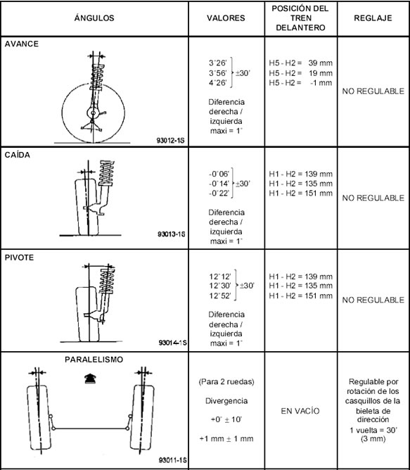
Qué es y como funciona el principio de Ackerman?

Cómo funciona?

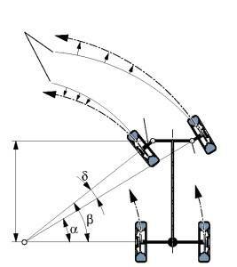
El principio de Ackerman enuncia que cuando un vehículo gira en una curva, los ejes de todas las ruedas deben concurrir en un punto, el centro instantáneo de rotación. La mangueta de la rueda interior debe de girar un ángulo mayor que la de la rueda exterior, luego se precisa una divergencia de las ruedas delanteras cuando se toman las curvas para evitar el desgaste de las cubiertas y evitar el deslizamiento. Con el mecanismo, anteriormente mencionado, conseguimos una geometría óptima para la dirección. Para seguir este principio se hace que el ángulo de giro de la rueda interior sea mayor que la exterior, es decir, como se muestra en la figura.

Cuando un vehículo describe una curva, todas las ruedas deben girar entorno al mismo centro instantáneo de rotación, permitiendo un mejor control y minimizando el desgaste de las ruedas. Cada una de las ruedas directrices debe por ello describir un arco de diferente radio, siendo el radio del arco que describe la rueda exterior mayor que el de la interior.

Se denomina centro instantáneo de rotación al punto respecto al cual un sólido está girando en un instante. La línea que une el centro instantáneo de rotación y un punto cualquiera del sólido es perpendicular a la velocidad de dicho punto.

Según Ackermann, el ángulo que forma la rueda exterior con la extensión del eje trasero (α) ha de ser menor que el formado por la interior (β).

244bbcw

Si un vehículo se diseña sin tener en cuenta el principio de Ackermann y las dos ruedas delanteras giran el mismo ángulo, no estarán girando con respecto al mismo punto. Esto genera inestabilidad y desgaste excesivo del neumático.

Untitled

En caso de aplicarse el principio de Ackermann, la rueda interior girará con mayor ángulo de forma que el centro instantáneo de rotación sea el mismo para todas las ruedas.

Para conseguir este efecto, las bieletas de dirección formarán cierto ángulo con el eje longitudinal, como se describe en la imagen inferior.

Jeantaud

El cálculo de Ackermann se basa en la fórmula:

Via/Batalla = cotg(α) – cotg(β)

La formula para calcular Ackermann se obtiene despejando α de la anterior, de modo que:

Ackermann = arctan ( batalla / (batalla/tan(β) – via) )

Porcentaje = 100 · ( α / Ackermann )

Un 100% Ackerman significa que las prolongaciones de las bieletas se cortan en el centro del eje trasero. En caso de que el porcentaje sea superior a 100, éstas se cortarán por delante del eje trasero; y detrás si es inferior.

Todo esto está muy bien en teoría, pero en la práctica los neumáticos se deforman. A esta deformación se la conoce como ángulo de deriva y es la diferencia entre el ángulo de giro y el ángulo que realmente adquiere la superficie de contacto del neumático debido a las fuerzas que se ejercen sobre él.

En los vehículos modernos no se utiliza un sistema de dirección Ackermann puro. Debido a la transferencia lateral de masas, las ruedas en las que la carga es menor, requieren menos ángulo de deriva para llegar a su límite de adherencia.

Para conseguir los efectos deseados en la geometría se debe introducir el concepto de convergencia.

True-Ackermann-Toe-In

Si la convergencia es positiva, las dos ruedas directrices tendrán cierta convergencia hacia el centro de las trayectorias, es decir, la rueda interior tratará de describir una circunferencia ligeramente mayor y la exterior una circunferencia ligeramente menor a la que está siguiendo. Con esta geometría se reduce el ángulo de deriva de la rueda interior y se aumenta el de la exterior.

En caso de que la convergencia sea negativa la rueda interior tratará de describir una circunferencia menor a la que está siguiendo y la exterior una circunferencia mayor. Con esta geometría el ángulo de deriva de la rueda interior aumenta, reduciéndose el de la rueda exterior.

Cuáles son los grados mecánicos que influyen en los neumáticos?

No photo description available.

Todos los vehículos de transporte vienen con una convergencia positiva para que al estar en movimiento, las ruedas tiendan a quedar paralelas. Esto ocurre porque el eje delantero, al ser empujado, permite una abertura de las ruedas, dentro de los límites de operación de los componentes de la dirección. Por lo tanto si las terminales estuvieren flojas más de lo normal tenderán a abrirse más, generando convergencia negativa.

Si el desgaste del neumático aparece a partir del hombro externo, indicará convergencia positiva en exceso.

La DIVERGENCIA significa que los bordes traseros de las llantas, ya sean del eje trasero o delantero, estarán más cerca entre sí que los bordes delanteros. La divergencia se usa comúnmente en autos de tracción delantera para contrarrestar la tendencia a converger mientras se conduce a velocidades altas. Alguna divergencia es necesaria para que los automóviles viren.

Si se tienen averías en los brazos auxiliares, estarán afectadas la convergencia y la divergencia en curvas, ambas produciendo el mismo síntoma de desgaste en los neumáticos (desgaste escamado a partir de los hombros internos, en dirección al centro de la banda de rodamiento). Esto ocurrirá porque las ruedas se abrirán más de lo necesario.

El CAMBER es el ángulo que forman por una parte una línea imaginaria de la rueda con una línea vertical y perpendicular al piso. El camber puede ser hacia dentro (camber negativo) o hacia fuera (camber positivo).

Todos los vehículos de transporte vienen con camber positivo, pues cuando el vehículo recibe su carga y es puesto en movimiento, la tendencia de las ruedas es de abrirse en la parte inferior.

Cuando el eje se desvía por sobrecarga, el camber queda negativo y el desgaste de los neumáticos se producirá a partir de los hombros internos, esto es porque las ruedas habrán quedado muy abiertas en la parte inferior.

El desgaste por camber incorrecto se acentúa en los hombros del neumático, no solo por la alteración de la distribución de peso, si no principalmente por generar dos diámetros diferentes dirigidos por el radio inferior, girando en torno al mismo eje.

Sistema de dirección de 4 ruedas, funcionamiento, requerimientos, modos de operación y aplicaciones

FOUR WHEEL STEERING SYSTEM: FUNCTIONS, REQUIREMENTS, MODES OF OPERATION AND APPLICATION

Four-wheel steering, 4WS, also called rear-wheel steering or all-wheel steering, provides a means to actively steer the rear wheels during turning maneuvers. A system that uses all four wheels to steer the car. The steering angle is usually limited to 2° or 3°. Turning the rear wheels in the opposite direction to the front at slow speeds can allow faster maneuvering and a much tighter turning radius. Turning the rear wheels in the same direction as those at the front at high speed allows sudden lane changes with much greater stability. Turning the rear wheels in the same direction as the front when parking makes parallel parking much easier. Four-wheel steering is a relatively new technology that improves maneuverability in cars, trucks and trailers.

FUNCTIONS

• To provide directional stability of vehicle
• To facilitate straight ahead recovery
• To minimize tire wear
• To absorb major parts of the road shocks
• To provide perfect rolling motions of the road wheels

REQUIREMENTS

No photo description available.

The steering system has the following requirements:

• The steering system must be able to turn the front wheels sharply yet easily and smoothly.
• The steering should be made lighter at low speeds and heavier at high speeds.
• Smooth recovery while the vehicle is turning.
• Minimum transmission of shock from road surface.

MODES OF 4WS

1. Two Wheel Steer: 
A 4-Wheel Steering System is flexible enough to work as a 2-wheel steer by restricting the rear wheel movement.

2. Four Wheel Steer/ Slow Speeds: 
Front wheel directions are opposite to rear wheel directions. This helps to take sharp turn with least turning radius.
At slow speeds, the rear wheels turn in the direction opposite to the front wheels. It can reduce the turning circle radius by 25%, and can be equally effective in congested city conditions, where U-turns and tight streets are made easier to navigate.

3. Crab Steer Mode/ High Speeds: 
At high speed lane change, both the front and rear wheels face in same direction.
In high speeds, turning the rear wheels through an angle opposite to front wheels might lead to vehicle instability and is thus unsuitable. Hence, at speeds above 80 kmph, the rear wheels are turned in the same direction of front wheels in four-wheel steering systems.

4. Zero turn: 
Front and Rear wheels are so aligned that the vehicle moves in a circle of ‘’zero radius’’.

APPLICATIONS

• Parking: 
During a parking a vehicles driver typically turns the steering wheels through a large angle to achieve a small tuning radius. By counter phase steering of the rear wheels, 4ws system realizes a smaller turning radius then is possible with 2ws system. As a result, vehicle is turned in small radius at parking.

• Junctions:
On a cross roads or other junction where roads intersect at 900 degrees or tighter angles, counter phase steering of the rear wheels causes the front and rear wheels to follow more or-less path. As a result, the vehicle can be turned easily at a junction.

• Slippery road surfaces: 
During steering operation on low friction surfaces, steering of the rear wheels suppress sideways drift of the vehicle’s rear end. As a result, the vehicles direction is easier to control.

• High-speed straight-line operation: 
When traveling in a straight line at high speed, a vehicle’s driver frequently needs to make small steering correction to maintain the desired direction, in phase steering of the rear wheels minimizes these corrective steering inputs.

• Narrow roads: 
On narrow roads with tight bends, counter-phase steering of the rear wheels minimizes the vehicle’s turning radius, thereby reducing side-to –side rotation of the steering wheels and making the vehicle easier to turn.

ADVANTAGES

• Car more efficient and stable on cornering.
• Improved steering responsiveness and precision.
• High-speed straight-line stability.
• Notable improvement in rapid, easier, safer lane changing maneuvers.
• Smaller turning radius and tight space maneuverability at low speed.
• Relative Wheel Angles and their Control.
• Risk of hitting an obstacle is greatly reduced

STEERING SYSTEM: REQUIREMENTS, TYPES, POWER STEER

Image may contain: motorcycle and outdoor

Automotive steering forms the basis of any vehicle’s motion control. It comprises of all components, joints, and linkages required to transfer power from the engine to the wheels. The steering also controls angles of the wheels in two axes for directionality.

REQUIREMENTS OF STEERING SYSTEM

No photo description available.

The steering system has the following requirements.

1 Excellent maneuverability When the vehicle is cornering on a narrow, twisting road, the steering system must be able to turn the front wheels sharply yet easily and smoothly.

2 Proper steering effort If nothing is done to prevent it, the steering effort will be greater when the vehicle is stopped and will decrease as the speed of the vehicle increase. Therefore, in order to obtain easier steering and a better feel of the road, the steering should be made lighter at low speeds and heavier at high speeds.

3 Smooth recovery While the vehicle is turning, the driver must hold the steering wheel firmly. After the turn is completed, however, recovery – that is, the return of the wheels to the straight-ahead position – should occur smoothly as the driver relaxes the force with which he is turning the steering wheel.

4 Minimum transmission of shock from road surface Loss of steering wheel control and transmission of kickback due to road surface roughness must not occur.

STEERING COMPONENTS

No photo description available.

1 Steering wheel Handles the steering operation.
2 Steering column Joins the steering wheel and the steering gears.
3 Steering gears Convert the steering torque and rotational deflection from the steering wheel, transmit them to the wheel through the steering linkage, and make the vehicle turn.
4 Steering linkage A steering linkage is a combination of the rods and arms that transmit the movement of the steering gear to the left and right front wheels.

TYPES OF STEERING SYSTEM

No photo description available.

Also, there are two types of steering.

• Rack-and-pinion type
• Recirculating-ball type

1. Rack & Pinion

Rack-and-pinion steering is the most common type of motion control mechanism in cars, small trucks and SUVs.

Construction
1. A Rack & Pinion gear set is enclosed in a metal tube with each end of the rack pointing out from the tube.
2. A rod – tie rod or axial rod – connects to each end of the rack.
3. The pinion gear is attached to the steering shaft.

Mechanism

When you turn the steering wheel the gear will spin, moving the rack. The tie rod connects to the steering arm, which is attached to a spindle.
The purpose of a Rack & Pinion gear is to convert the circular motion of the steering wheel into the linear motion. It allows gear reduction, making it easier to turn the wheels.

The two types of rack-and-pinion steering systems:
1. End take-off
2. Centre take-off

Variable Ratio Steering

A subtype of Rack & Pinion gear steering is Variable Ratio Steering.
This steering system has a different number of tooth pitch at the center than it has at the ends.
This makes the steering less sensitive when the steering wheel is close to its center position.
And when it is turned towards the lock, the wheels become more sensitive to the circular motion of the steering wheel.

2. Re-circulating Ball / Steering Box

Re-circulating Ball Steering is the most commonly used steering system in heavy automobiles.
It runs on Parallelogram linkage, in which:
1. The Pitman & Idler arm remains parallel
2. The mechanism absorbs heavy shock loads and vibrations

Construction
1. The steering wheel is fixed to the steering shaft, which has a threaded rod at the end. The threaded rod is fixed, unlike in the Rack & Pinion type.
2. The block has gear teeth machined ON its surface.
3. The threads in the rod are filled with ball bearings.
4. These ball bearings have two functions: To reduce friction and wear in the gear; Fixing the teeth of the gear to prevent the former from breaking contact with each other when the steering wheel changes direction.

Mechanism
1. When the steering wheel is rotated, the rod turns.
2. When the wheel spins, the block moves.
3. The block moves another gear that in turn moves the Pitman’s arm.
4. The ball bearings in the threads re-circulate through the gear as it turns.

POWER STEERING

To improve driving comfort, most modern automobiles have wide, low-pressure tires which increase the tire-to-road surface contact area. As a result of this, more steering effort is required. Steering effort can be decreased by increasing the gear ratio of the steering gear. However, this will cause a larger rotary motion of the steering wheel when the vehicle is turning, making sharp turns impossible. Therefore, to keep the steering agile and, at the same time the steering effort small, some sort of a steering assist device became necessary. In other words, power steering, which had been chiefly used on larger vehicles, is now also used on compact passenger cars.

Type of power steering
There are hydraulic type and electric type power steering. Currently, hydraulic power steering is used on almost all models. The three main components of hydraulic power steering are the vane pump, control valve, and power cylinder.

Operation of hydraulic power steering

No photo description available.

The power steering system uses the power of the engine to drive the vane pump that generates hydraulic pressure. When the steering wheel is turned, an oil circuit is switched at the control valve. As oil pressure is applied to the power piston in the power cylinder, the power needed to operate the steering wheel is reduced. It is necessary to inspect for leakage of power steering fluid periodically.

Vane Pump

Power steering is a type of hydraulic device requiring very high pressure. It uses the power of the engine to drive the vane pump uses that generates this hydraulic pressure. Vanes are used in this pump, so this name is used for this type of power steering.

STEERING MECHANISMS

No photo description available.

1. TELESCOPIC MECHANISM

The telescopic steering mechanism allows forward or backward adjustment of the steering wheel position to suit the driver’s posture.

Construction
The telescopic mechanism consists of the sliding shaft tube, two wedge locks, stopper bolt, telescopic lever, etc.

Operation
The wedge locks move together with the operation of the telescopic lever. When the telescopic lever is in the lock position, the telescopic lever presses the wedge locks against the sliding shaft tube, locking the sliding shaft tube. On the other hand, when the telescopic lever is moved to the free position, a gap is created between the wedge locks and the sliding shaft tube and the steering column can be adjusted in the forward or backward direction.

2. TILT STEERING MECHANISM

The tilt steering mechanism allows selection of the steering wheel position (in the vertical direction) to match the driver’s driving posture. The tilt steering mechanisms are classified into the upper fulcrum type and the lower fulcrum type. Here, the lower fulcrum type is explained.

Construction
The tilt steering mechanism consists of a pair of tilt steering stoppers, tilt lock bolt, breakaway bracket, tilt lever, etc.

Operation
The tilt steering stoppers turn together with the operation of the tilt lever. When the tilt lever is in the lock position, the peaks of the tilt steering stoppers are lifted up and the stoppers push against the breakaway bracket and tilt attachment, locking the breakaway bracket and tilt attachment. On the other hand, when the tilt lever is moved to the free position, the height difference on the tilt steering stoppers is eliminated, and the steering column can be adjusted in the vertical direction.

Copyright © All rights reserved. | StoreCommerce by AF themes.
YouTube
YouTube
Instagram