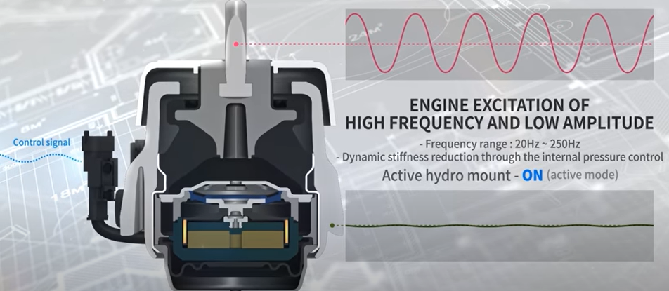
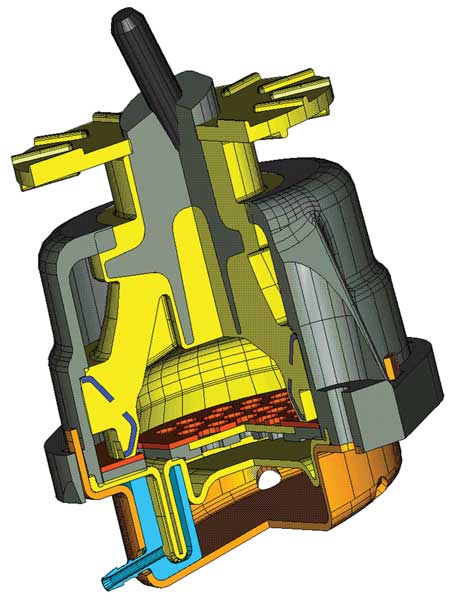
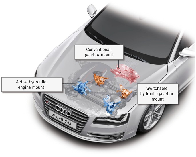
Los soportes de motor activos, es un dispositivo que mantiene el motor unido al chasis mediante el uso de una cámara que se encuentra rellena de fluido hidráulico y otro segmento se encuentra magnetizado este es controlado electronicamente mediante una ECU de motor que utiliza datos como aceleración del vehículo, RPM de motor para hacer el cálculo de oscilaciones mediante la frecuencia obtenida por el sensor del soporte que lo lleva a la ECU ahí hace el balance de movimiento para que se reduzcan las vibraciones y haga un sólo movimiento uniforme
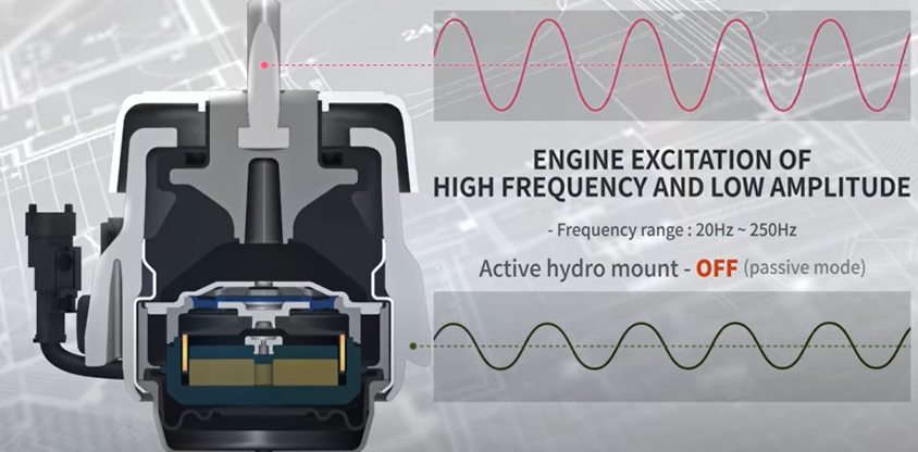
Únicamente se mueve la cámara de arriba debido a que son las vibraciones del motor en ralenti
Las oscilaciones de ambas cámaras son diferentes debido a que entra en movimiento el chasis y el motorCuando entra en movimiento el chasis y el motor se sincronizan las oscilaciones de ambas cámaras para reducir las vibraciones en un solo movimiento
Los montajes activos del motor reducen la excitación de vibraciones indeseables del motor al generar contra-oscilaciones compensadoras.
Un soporte de motor activo es similar a un soporte hidraulico en que tiene una cámara que se puede llenar con aire o fluido. Pero la cantidad de amortiguación se puede cambiar en una montura activa. Se puede configurar para que absorba más vibraciones y movimientos al ralentí, pero se endurece a velocidades más altas. Los fabricantes de automóviles Honda, Hyundai, Jaguar, Lexus Toyota y otros cambiaron a soportes de motor activos a partir de 2005.
Una forma de variar la rigidez de un soporte de motor activo es usar un actuador de vacío. Al aspirar el aire fuera de la cámara, el soporte del motor activo se parece más a un soporte de motor tradicional, confiando más en la rigidez del caucho que en la cámara de aire. El PCM sabe cuándo el motor está en ralentí, un período en el que produce la mayor vibración y activa una válvula de conmutación de vacío cíclica (VSV) para aplicar el vacío del colector de admisión a la cámara de aire para que absorba más vibración. A velocidades más altas del motor, el VSV permite que ingrese más aire en el soporte activo del motor, lo que aumenta su rigidez.
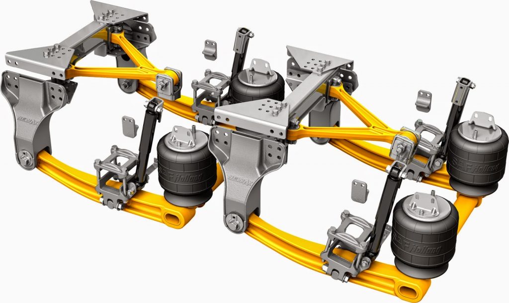
La suspensión neumática se encuentra instalada en la parte trasera de los camiones y vehículos de carga, incluyendo ciertos tipos de autobuses, tractocamiones o semirremolques, uno de los componentes fundamentales que lo hacen llamarse así son los fuelles
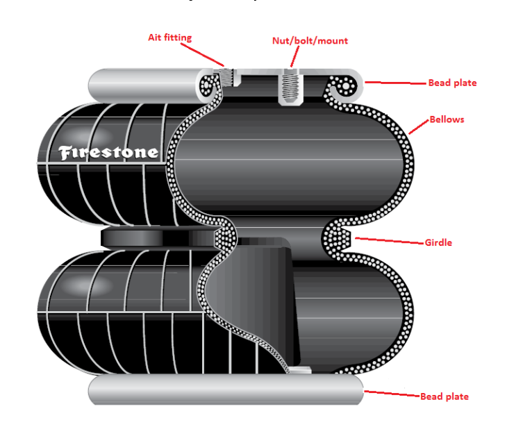
Los fuelles es un dispositivo neumático que básicamente es fabricando como una especie de bolsa que en su interior se encuentra un gas por lo regular aire que hace la función de un resorte reduciendo vibraciones y brindando una mejor estabilidad a la unidad, así como brindar una conducción más segura y suave al operador del vehículo independientemente de la carga a la cual está sometido el camión
Los materiales con los cuales estan fabricados los fuelles son
Ventajas principales de la suspensión neumática para vehículos de carga
– Más comodidad en el manejo de la carga en el caso de los tractocamiones debido al sencillo sistema de enganche y desenganche del remolque.
– Mayor fiabilidad y seguridad a la hora de transportar productos frágiles gracias a la absorción uniforme de las irregularidades del terreno y a un menor nivel de vibración en la zona de carga del vehículo durante la conducción.
– Permite transportar un mayor nivel de carga manteniendo la distancia de ésta con la carretera de manera uniforme en todo momento.
– Un mayor nivel de seguridad en lo que se refiere al control del frenado en función de la carga transportada.
– Su funcionamiento y puesta en práctica garantiza una mejor conservación de las carreteras, consiguiendo que el peso del camión y la carga transportada tenga un menor impacto en el asfalto durante el transporte.
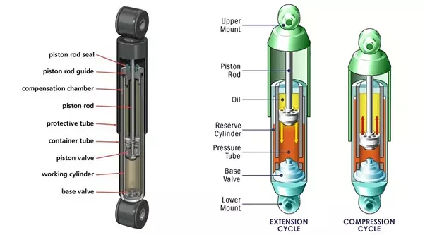
Los amortiguadores son básicamente bombas de aceite. Un pistón está fijado al extremo del vástago del pistón y actúa contra el fluido hidráulico en el tubo de presión. A medida que la suspensión sube y baja, el fluido hidráulico pasa a través de pequeños orificios, llamados orificios, dentro del pistón. Sin embargo, estos orificios sólo dejan pasar una pequeña cantidad de líquido a través del pistón. Esto desacelera el pistón, lo que a su vez desacelera el movimiento del resorte y la suspensión.
Todos los amortiguadores modernos son dispositivos de amortiguación hidráulica sensibles a la velocidad, lo que significa que cuanto más rápido se mueve la suspensión, más resistencia proporciona el amortiguador.
Gracias a esta característica, los amortiguadores se ajustan a las condiciones de la carretera. Como resultado, los amortiguadores reducen la tasa de:
Rebotar
Rodar o balancearse
Zambullida con freno y sentadilla con aceleración
Los amortiguadores funcionan según el principio de desplazamiento de fluido tanto en el ciclo de compresión como en el de extensión. Un automóvil o camioneta típico tendrá más resistencia durante su ciclo de extensión que durante su ciclo de compresión. El ciclo de compresión controla el movimiento del peso no suspendido de un vehículo, mientras que la extensión controla el peso suspendido más pesado.
FUNCIONES DEL AMORTIGUADOR
La función principal del amortiguador es absorber los impactos y amortiguarlos lo antes posible para que se pueda obtener una conducción suave.
Algunas otras funciones importantes del amortiguador son Limita el movimiento de la carrocería del vehículo. Estabiliza nuestro viaje como se mencionó anteriormente. Estabiliza los neumáticos del vehículo que se alteran debido a un impacto repentino, por lo que también es muy importante por motivos de seguridad. También minimiza el desgaste de los neumáticos y la carrocería del automóvil y, por lo tanto, reduce el costo general de mantenimiento. Puede parecer un trabajo sencillo, pero esto es lo principal de lo que depende el nivel de comodidad de su viaje.
PRINCIPIO DE FUNCIONAMIENTO
Para entender el amortiguador, es muy importante entender su funcionamiento.
En primer lugar debemos saber que generalmente existen dos tipos de amortiguadores uno es hidráulico y otro es neumático. Sin embargo, el funcionamiento de ambos tipos de amortiguadores es el mismo.
Un amortiguador generalmente está acoplado a un resorte, que convierte ondas de choque repentinas en movimiento oscilatorio. Este movimiento oscilatorio nos brinda un alivio instantáneo del impacto, pero nadie puede recorrer todo el recorrido con estas oscilaciones.
Aquí surge la necesidad de un amortiguador, que se utiliza para amortiguar las oscilaciones que producen los resortes. Un amortiguador general contiene un pistón perforado en una cámara hidráulica. La cámara está totalmente sellada por lo que si el pistón tiene que hacer algún movimiento la única manera es dejar pasar el líquido hidráulico a través de él.
Cuando se produce un choque, el pistón tiene que moverse debido al choque. Cuando el pistón se mueve, el líquido hidráulico del amortiguador tiene que pasar a través de él.
Cuando el líquido pasa a través de los diminutos orificios perforados del pistón, el pistón tiene que trabajar un poco contra él. Ese trabajo se realiza a expensas de la energía generada debido al choque y, por lo tanto, pronto el amortiguador pierde toda la energía del choque, lo que resulta en una marcha suave y sin oscilaciones.
TIPOS DE DISEÑO DE AMORTIGUADORES
Actualmente se utilizan varios diseños de amortiguadores:
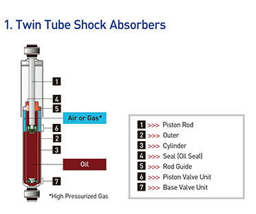
Diseños de doble tubo
Gas cargado
PSD (amortiguación sensible a la posición)
ASD (amortiguación sensible a la aceleración)
Monotubo
A. Tubo doble: diseño cargado con gas
La función principal de la carga de gas es minimizar la aireación del fluido hidráulico. La presión del gas nitrógeno comprime las burbujas de aire en el fluido hidráulico. Esto evita que el aceite y el aire se mezclen y formen espuma. La espuma afecta el rendimiento porque se puede comprimir, pero el fluido no. Con la aireación reducida, el amortiguador puede reaccionar más rápido y de manera más predecible, lo que permite un tiempo de respuesta más rápido y ayuda a mantener el neumático firmemente plantado en la superficie de la carretera.
Ventajas:
Mejora el manejo al reducir el balanceo, el balanceo y la caída.
Reduce la aireación y ofrece un mayor rango de control sobre una variedad más amplia de condiciones de la carretera en comparación con las unidades sin gasolina.
Menor desvanecimiento: los amortiguadores pueden perder capacidad de amortiguación a medida que se calientan durante el uso. Los amortiguadores cargados con gas podrían reducir esta pérdida de rendimiento, llamada desvanecimiento
B. Tubo doble – Diseño PSD
Los ingenieros de conducción tuvieron que hacer concesiones entre válvulas suaves y válvulas firmes. Con válvulas suaves, el fluido fluye más fácilmente. El resultado es una marcha más suave, pero con un manejo deficiente y mucho balanceo. Cuando la válvula es firme, el fluido fluye con menos facilidad. Se ha mejorado el manejo, pero la marcha puede volverse dura. Con la llegada de la carga de gas, los ingenieros de viajes pudieron abrir los controles de orificio de estas válvulas y mejorar el equilibrio entre la comodidad y las capacidades de control disponibles en los amortiguadores tradicionales sensibles a la velocidad. Un salto más allá del control de la velocidad del fluido es una tecnología avanzada que tiene en cuenta la posición de la válvula dentro del tubo de presión. Esto se llama amortiguación sensible a la posición (PSD). La clave de esta innovación son las ranuras cónicas de precisión en el tubo de presión. Cada aplicación se ajusta individualmente, adaptando la longitud, profundidad y conicidad de estas ranuras para garantizar una comodidad de marcha óptima y mayor control. En esencia, esto crea dos zonas dentro del tubo de presión. La primera zona, la zona de confort, es donde se realiza la conducción normal. La segunda zona, la zona de control, se utiliza durante situaciones de conducción exigentes.
Ventajas:
Permite a los ingenieros de conducción ir más allá de la simple válvula sensible a la velocidad y utilizar la posición del pistón para ajustar la característica de conducción.
Se ajusta más rápidamente a las condiciones cambiantes de la carretera y del peso que los amortiguadores estándar
Dos amortiguadores en uno: comodidad y control
C. Tubo doble: diseño ASD (réflex)
Un nuevo giro en el compromiso comodidad/control es una tecnología innovadora que proporciona un mayor control para el manejo al tiempo que mejora la comodidad de marcha llamada Amortiguación Sensible a la Aceleración (ASD). Esta tecnología va más allá de la amortiguación tradicional sensible a la velocidad para enfocar y abordar el impacto. Este enfoque en el impacto se logra mediante la utilización de un nuevo diseño de válvula de compresión. Esta válvula de compresión es un sistema mecánico de circuito cerrado que abre un bypass para que el fluido fluya alrededor de la válvula de compresión.
Ventajas:
Se mejora el control sin sacrificar la comodidad del conductor
La válvula se ajusta automáticamente a los cambios en las condiciones de la carretera
Reduce la dureza de la marcha
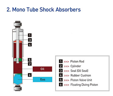
Diseño monotubo (tipos estándar)
Se trata de amortiguadores de gas a alta presión con un solo tubo, el tubo de presión. Dentro del tubo de presión hay dos pistones: un pistón divisor y un pistón de trabajo. El pistón y la varilla de trabajo son muy similares al diseño del amortiguador de doble tubo. La diferencia en la aplicación real es que un amortiguador monotubo se puede montar boca abajo o boca arriba y funcionará de cualquier manera. Además de su flexibilidad de montaje, los amortiguadores monotubo son un componente importante, junto con el resorte, para soportar el peso del vehículo. Otra diferencia que puedes notar es que el amortiguador monotubo no tiene válvula de base. En cambio, todo el control durante la compresión y extensión se realiza en el pistón. Durante la operación, el pistón divisor se mueve hacia arriba y hacia abajo a medida que el vástago del pistón entra y sale del amortiguador, manteniendo el tubo de presión lleno en todo momento.
Ventajas:
Puede montarse boca abajo, lo que reduce el peso no suspendido
Puede funcionar a menor temperatura ya que el tubo de trabajo está expuesto al aire
Equipo original en muchos vehículos de pasajeros, SUV y camionetas livianas nacionales importados y de alto rendimiento.
El sistema de suspensión de un automóvil es una de las partes más críticas de un automóvil. A menudo pasa desapercibido ya que su funcionamiento es silencioso. Pero sin suspensión es difícil imaginarse conduciendo un coche. Entonces, ¿para qué sirve un sistema de suspensión en un coche?
La función principal del sistema de suspensión en un automóvil es mantener el vehículo estable anulando las fuerzas externas. Aquí, las fuerzas externas no son más que las fuerzas que siente la carrocería del coche debido a los baches, baches, etc., en la carretera. Además, la suspensión mantiene el coche estable en las curvas y a altas velocidades y ofrece un manejo superior.
Un sistema de varillajes mecánicos, resortes y amortiguadores que se utiliza para conectar las ruedas al chasis se conoce como sistema de suspensión. Por lo general, realiza dos trabajos: controlar el manejo y el frenado del vehículo por razones de seguridad y mantener a los pasajeros cómodos frente a golpes, vibraciones, etc.
También ayuda a mantener la altura correcta del vehículo y la alineación de las ruedas. También controla la dirección del vehículo y debe mantener la rueda en una dirección perpendicular para su máximo agarre. La suspensión también protege el vehículo y el equipaje de daños y desgaste. El diseño de la suspensión delantera y trasera de un automóvil puede ser diferente.
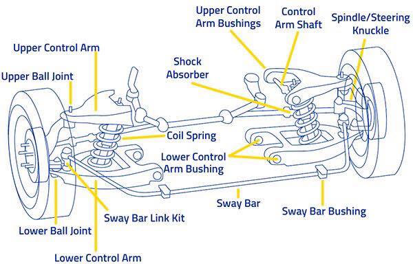
COMPONENTES DEL SISTEMA DE SUSPENSIÓN
Un sistema de suspensión, independientemente de su tipo, tiene algunos componentes principales en común que son:
Knuckle or Upright-
Es el componente del sistema de suspensión que está montado sobre el cubo de la rueda a través del cual las ruedas y la suspensión del vehículo se conectan entre sí mediante los enlaces provistos. Se proporciona un muñón con el pivote central y los ángulos de avance que ayudan a las ruedas delanteras del vehículo a girar en dirección derecha o izquierda, lo que a su vez dirige el vehículo. Una articulación proporciona alojamiento para el cojinete central sobre el cual gira el cubo de la rueda junto con la rotación de las ruedas.
Links
Los varillajes son las conexiones rígidas que se utilizan en el sistema de suspensión para conectar el bastidor principal del vehículo con la articulación de las ruedas a través de sujetadores mecánicos.
Según el tipo de suspensión, los enlaces utilizados son de 3 tipos:
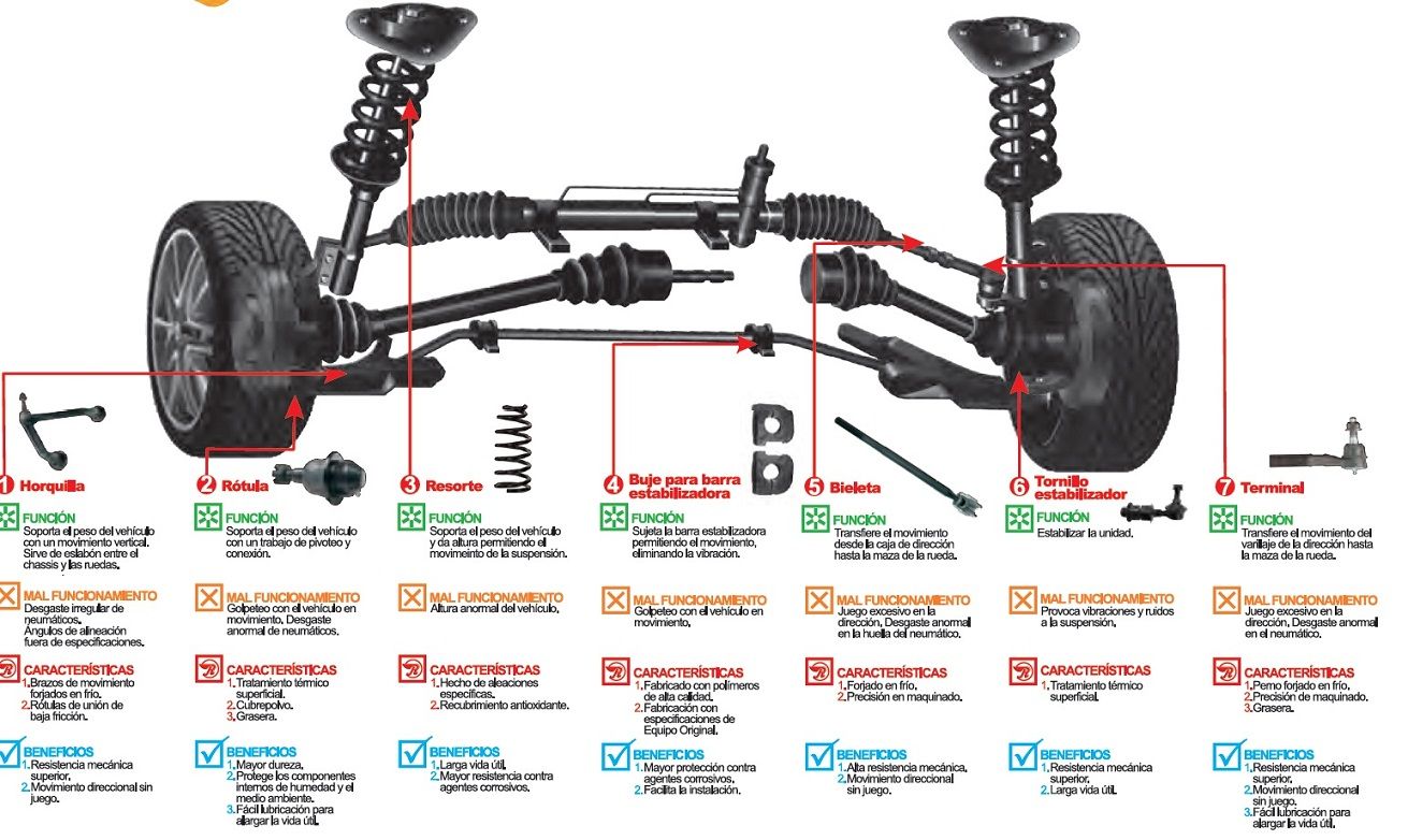
i. Horquillas o brazo en A Es el tipo de varillaje mecánico que tiene la forma del alfabeto A, el extremo puntiagudo del brazo en A está sujeto al nudillo y los otros 2 extremos del brazo en A están sujetos al bastidor principal del vehículo. En función de la aplicación del vehículo, se utiliza un brazo A simple o un brazo A doble.
ii. Eje macizo o eje vivo. Es el tipo de varillaje que se utiliza para conectar el bastidor principal del vehículo con el muñón de la rueda, esta es la carcasa del eje sólido que soporta el peso total del vehículo, este tipo de varillaje se puede ver en camiones.
III. Múltiples enlaces- En lugar de utilizar doble horquilla o varillaje de eje sólido, varios automóviles de alta gama están adoptando un tipo de suspensión de vínculo múltiple en el que se utilizan múltiples vínculos sólidos para conectar el bastidor principal del vehículo al muñón de la rueda.
Amortiguadores o resortes.
Son los componentes mecánicos flexibles que se utilizan para absorber los impactos proporcionados por las condiciones de la carretera y se colocan entre los varillajes (espoleta. Eje sólido, enlaces múltiples) y el bastidor principal de modo que el impacto de la carretera se minimice antes de transmitirse al bastidor principal de un vehículo.
Según la aplicación y el tipo de suspensión, los amortiguadores utilizados son de muchos tipos que son:
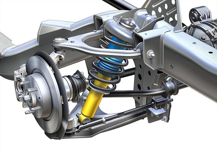
i. Amortiguador tipo resorte y amortiguador- Es el tipo de amortiguador en el que se utiliza un pistón neumático o hidráulico conocido como amortiguador que proporciona amortiguación absorbiendo los impactos de la carretera.
Este amortiguador está rodeado por un resorte helicoidal de compresión que es una restricción mecánica elástica que se comprime cuando el golpe aplica fuerza y retrocede o recupera su forma y tamaño originales cuando se elimina la fuerza.
Se utiliza para mantener la superficie de contacto de los neumáticos con la carretera proporcionando rigidez (resistencia a la compresión), además mantiene el amortiguador en su longitud original después de absorber el impacto.
Ballesta Es el tipo de resorte en el que una serie de placas de metal dúctil llamadas láminas están dispuestas en un patrón especial, es decir, una sobre una en orden ascendente de su longitud, las láminas del amortiguador de láminas están pretensadas de tal manera que cuando el choque es transferidas por las ruedas, estas hojas pretensadas al ser dúctiles intentan recuperar su forma original, es decir, enderezarse. Por lo que el impacto es absorbido por las hojas.
Este tipo de amortiguador se puede ver fácilmente en camiones en la carretera en los que se utiliza un amortiguador de ballesta entre el eje sólido o vivo y el bastidor principal del vehículo.
Aire Es el último tipo de amortiguador que se puede ver fácilmente en los autobuses Volvo; en los amortiguadores de resorte neumático la amortiguación del impacto es una función de la compresión del aire, lo que significa que se utiliza aire como amortiguador. El aire necesario para diferentes condiciones de carga es controlado y monitoreado por la unidad de control eléctrico del vehículo.
TIPOS DE SISTEMA DE SUSPENSIÓN
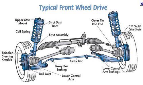
1) SISTEMA DE SUSPENSIÓN INDEPENDIENTE
Este sistema significa que la suspensión está configurada de tal manera que permite que las ruedas del lado izquierdo y derecho del vehículo se muevan verticalmente de forma independiente hacia arriba y hacia abajo mientras se conduce sobre una superficie irregular. Una fuerza que actúa sobre una sola rueda no afecta a la otra ya que no existe ningún vínculo mecánico entre los dos cubos del mismo vehículo. En la mayoría de los vehículos se emplea en las ruedas delanteras. Este tipo de suspensión suele ofrecer una mejor calidad de marcha y manejo debido a que tiene menos peso no suspendido. La principal ventaja de la suspensión independiente es que requiere menos espacio, proporciona una maniobrabilidad más fácil, peso reducido, etc. Ejemplos de suspensión independiente son
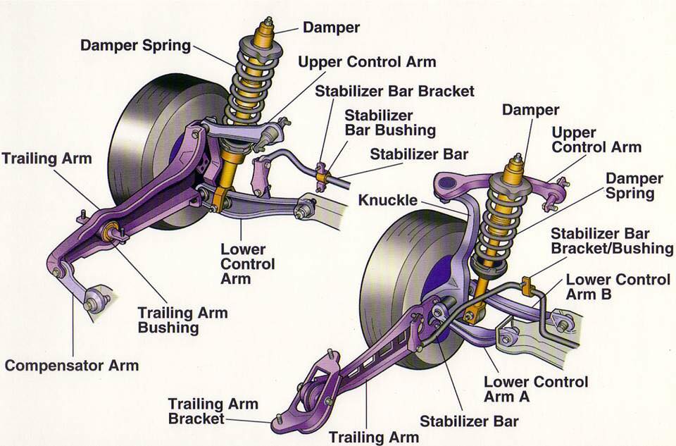
i. Double Wishbones
It is an independent suspension system design using two wishbone-shaped arms(called A-ARM in USA and WISHBONE in the UNITED KINGDOM)to locate the wheel. Each wishbone or arm has two mounting points to the chassis and one joint at the knuckle. The angle movements of the compressing and rebounding wheels can be managed by using arms of unequal length. The main advantage of the double-wishbone suspensions is that they allow easy adjustments of camber, toe and other properties. This type of suspension also provides increasing negative camber gain all the way to full jounce travel. On the other hand, it takes more space and is slightly more complex than the other system like Macpherson strut. It also offers less design choice.
ii. MacPherson Strut
Opción de la suspensión de doble horquilla. La principal ventaja del MacPherson es que todas las piezas que proporcionan la suspensión y el control de las ruedas se pueden combinar en un solo conjunto.
Facilita la instalación en motor transversal. Este diseño es muy popular debido a su sencillez y bajo coste de fabricación. La desventaja es que es más difícil aislar del ruido de la carretera. Para ello es necesario un soporte de puntal superior, que debe estar lo más desacoplado posible. También requiere una mayor altura libre.
2) SISTEMA DE SUSPENSIÓN DEPENDIENTE
EN Suspensión dependiente hay un enlace rígido entre las dos ruedas del mismo eje. Una fuerza que actúa sobre una rueda afectará a la rueda opuesta. Por cada movimiento de la rueda provocado por la carretera, las irregularidades afectan también a la rueda acoplada. Se emplea principalmente en vehículos pesados. Puede soportar golpes con mayor capacidad que la suspensión independiente. Ejemplo de este sistema es
I. Eje macizo. Un eje macizo o un eje de viga es un tipo de suspensión dependiente. Se utiliza principalmente en ruedas traseras en las que el eje trasero está soportado y ubicado por dos ballestas. El movimiento vertical de una rueda influye en la otra. Son sencillos y económicos de fabricar. Son tan rígidos que no hay cambios en el ancho de vía, la convergencia y la inclinación en un bache lleno, lo que ayuda a reducir el desgaste de los neumáticos. La principal desventaja es que la masa de la viga está incluida en el peso no suspendido del vehículo, lo que da como resultado una baja calidad de marcha. La capacidad para tomar curvas también es pobre debido al ángulo de caída cero.
3) SISTEMA SEMIINDEPENDIENTE
Este tipo de sistema tiene características tanto de suspensión dependiente como independiente. En la suspensión semiindependiente, las ruedas se mueven entre sí como en la suspensión independiente, pero la posición de una rueda tiene algún efecto sobre la otra. Esto se hace girando las piezas de suspensión. Ejemplo de semiindependiente es
i. Haz giratorio La suspensión de viga de torsión también se conoce como eje de viga de torsión. Estos se basan principalmente en miembros en forma de C o H. La viga transversal en forma de H mantiene unidos los dos brazos de arrastre y proporciona rigidez a la suspensión. Se utiliza principalmente en la rueda trasera de los coches. Es muy favorable por su bajo coste y es muy duradero. Tiene un diseño sencillo y es muy ligero. Pero, por otro lado, el ángulo de caída es limitado y la rigidez del balanceo tampoco es muy fácil. Las características de los dedos pueden ser inadecuadas.
La barra estabilizadora de la suspensión de un vehículo es una barra de acero con propiedades de naturaleza elástica, que se encuentra fijada en sus extremos a cada soporte de la suspensión de cada lado del mismo eje.
Todo vehículo circulando a velocidad por una curva se ve sometido a una fuerza centrífuga que hace que se incline hacia un costado, que puede generar una sensación de molestia en los ocupantes del vehículo, además de poder existir un peligro real de vuelco del vehículo si la velocidad fuera inadecuadamente excesiva.
Esto es así debido a la fuerza centrífuga que actúa sobre el vehículo, que es de dirección radial y ejerce un empuje sobre el vehículo que tira de él hacia el exterior de la curva.
Esta fuerza genera una transferencia de carga en el vehículo que hace inclinar a la carrocería de tal forma que una parte de la suspensión, la situada en el lado exterior a la curva, se comprima, mientras que la otra parte de la suspensión del vehículo, la situada hacia el interior de la curva, se expanda corriendo el riesgo de despegar la rueda de este lado del pavimento.
Este hecho, es decir, que las ruedas de un lado del vehículo tiendan a subir, mientras que las ruedas del otro lado tiendan a bajar comprimiéndose contra el suelo, va a generar un par de torsión que es absorbido por la barra estabilizadora, impidiendo que la carrocería se incline excesivamente hacia un lado y ejerciendo una resistencia al balanceo del vehículo.
Así, el movimiento vertical hacia arriba de la rueda situada del lado interior de la curva se transmite a la otra rueda del eje a través de la barra estabilizadora, que tiende a bajar la carrocería de ese lado comprimiendo el muelle de la suspensión, de manera que se consigue sumar la acción de los dos muelles, ayudando a mantener la estabilidad del vehículo.
Por ello, la barra estabilizadora se considera un componente elástico de la suspensión dado que actúa en parte también como muelle, especialmente cuando actúa sobre la rueda del lado del eje que tiende a subir.
Este mismo efecto se produce, no sólo cuando el vehículo toma una curva, sino cuando por ejemplo, una de las ruedas encuentra un bache o cualquier obstáculo, creando, al bajar o subir la rueda, un par de torsión en la barra que hace que la carrocería se mantenga en posición horizontal. De esta forma, como se ha dicho, se consigue sumar la acción de los dos muelles.
Por tanto, la barra estabilizadora de la suspensión de un vehículo trabaja a torsión, compensando los esfuerzos generados de una rueda sobre la otra del eje mediante una transferencia de peso de la rueda que se comprime hacia la rueda del lado que tiende a elevarse, aumentando así su adherencia.
De este modo, se evita que el muelle de un lado de la suspensión se comprima excesivamente, mientras que el otro muelle se expanda, pudiendo hacer perder el contacto de la rueda con el piso.