¿Qué es el Turbocompresor, y cómo trabaja?

Un turbocompresor es un dispositivo que se utiliza para aumentar la potencia del motor o se puede decir la eficiencia de un motor al aumentar la cantidad de aire que ingresa a la cámara de combustión. Más aire en la cámara de combustión significa que se admitirá más cantidad de combustible en el cilindro y, como resultado, se obtendrá más potencia del mismo motor si el turbocompresor está instalado en él.

En pocas palabras, un turbocompresor es una especie de bomba de aire que toma aire a presión ambiental (presión atmosférica), lo comprime a una presión más alta y pasa el aire comprimido al motor a través de las válvulas de admisión.

Actualmente, los turbos se utilizan principalmente en motores diésel, pero actualmente se está avanzando hacia la turbocompresión en los motores de gasolina de serie.

La cantidad de motor que realmente entra en el cilindro del motor, en comparación con la cantidad teórica si el motor pudiera mantener la presión atmosférica, se llama eficiencia volumétrica y el objetivo del turbocompresor es mejorar la eficiencia volumétrica de un motor aumentando la densidad del gas de admisión. .

El turbocompresor extrae el aire de la atmósfera y lo comprime con la ayuda de un compresor centrífugo antes de que entre en el colector de admisión a mayor presión. Esto da como resultado una mayor cantidad de aire que ingresa a los cilindros en cada carrera de admisión. El compresor centrífugo obtiene energía de la energía cinética de los gases de escape del motor.

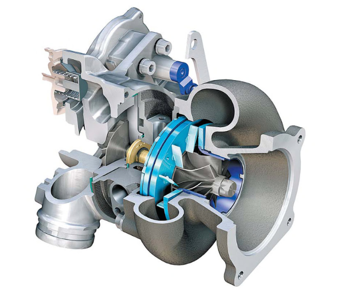
COMPONENTES DEL TURBOCARGADOR

El turbocompresor tiene tres componentes principales.

  • 1. La turbina, que es casi una turbina de entrada radial.
  • 2. El compresor es casi un compresor centrífugo.
  • 3. El conjunto giratorio del cubo central.

Un turbocompresor se compone de dos secciones principales: la turbina y el compresor. La turbina consta de una rueda de turbina y una carcasa de turbina. La función de la carcasa de la turbina es guiar los gases de escape hacia la rueda de la turbina.

La energía de los gases de escape hace girar la rueda de la turbina y luego el gas sale de la carcasa de la turbina a través de un área de salida de escape. El compresor también consta de dos partes: la rueda del compresor y la carcasa del compresor.

El modo de acción del compresor es opuesto al de la turbina. La rueda del compresor está unida a la turbina mediante un eje de acero forjado y, a medida que la turbina hace girar la rueda del compresor, el giro a alta velocidad aspira aire y lo comprime.

Luego, la carcasa del compresor convierte la corriente de aire de alta velocidad y baja presión en una corriente de aire de alta presión y baja velocidad mediante un proceso llamado difusión. El aire comprimido ingresa al motor, lo que le permite quemar más combustible para producir más potencia.

PRINCIPIO DE FUNCIONAMIENTO

Un turbocompresor consta principalmente de dos secciones principales: la turbina y el compresor. La turbina consta de una rueda de turbina y una carcasa de turbina, cuya función es conducir los gases de escape hacia la rueda de turbina. La energía cinética de los gases de escape se convierte en mecánica después de golpear los álabes de la turbina. La salida de escape ayuda a que los gases de escape salgan de la turbina. La rueda del compresor en el turbocompresor está unida a una turbina con la ayuda de un eje de acero y, a medida que la turbina hace girar la rueda del compresor, aspira la corriente de aire de alta velocidad y baja presión y la convierte en aire de alta presión y baja velocidad. arroyo. Este aire comprimido ingresa al motor con mayor cantidad de combustible y, por lo tanto, produce más potencia.

Los gases de escape residuales del motor se utilizan para accionar una rueda de turbina, que está conectada a una rueda de compresor mediante un eje. El compresor o rueda de aire aspira aire a través de los filtros de aire y lo pasa al motor.
A medida que los gases residuales son expulsados ​​del motor, se dirigen a la turbina o rueda caliente del turbo y así completa el ciclo.

  1. Captura

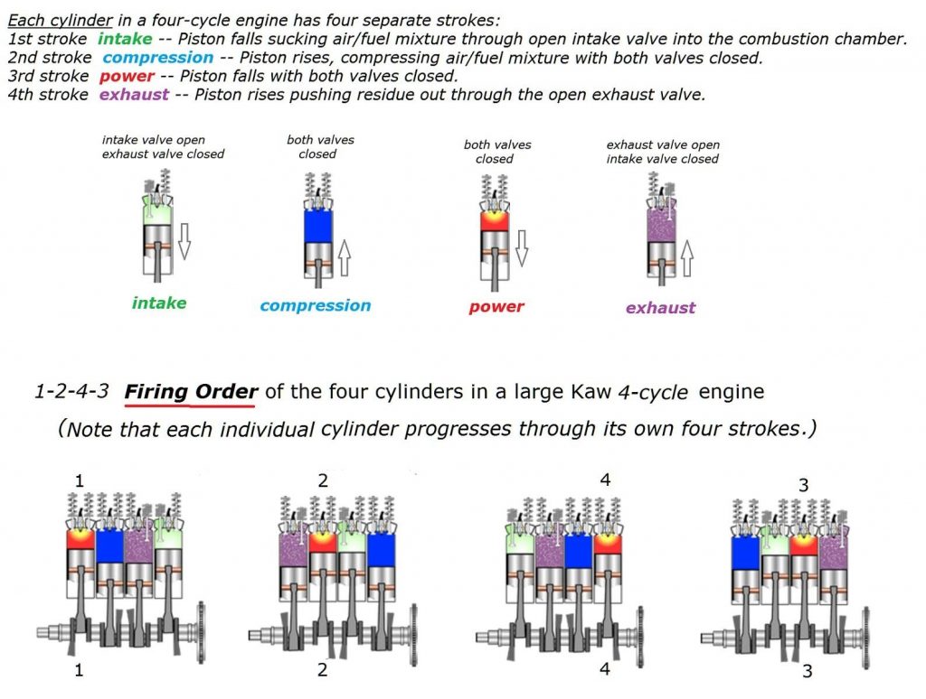
En lugar de escapar por el tubo de escape, los gases calientes producidos durante la combustión fluyen hacia el turbocompresor. Los cilindros dentro de un motor de combustión interna se disparan en secuencia (no todos a la vez), por lo que los gases de escape salen de la cámara de combustión en pulsos irregulares.
Los turbocompresores convencionales de entrada única dirigen esos pulsos irregulares de escape hacia la turbina de una manera que los hace chocar e interferir entre sí, reduciendo la fuerza del flujo. Por el contrario, un turbocompresor de doble entrada recoge los gases de escape de pares de cilindros en una secuencia alterna.

  1. Girar

El escape golpea las palas de la turbina, haciéndolas girar hasta 150.000 rpm. Los pulsos alternos del escape ayudan a eliminar el retraso del turbo.

  1. Ventilación

Una vez cumplido su propósito, los gases de escape fluyen a través de una salida hacia el convertidor catalítico, donde se eliminan el monóxido de carbono, los óxidos nitrosos y otros contaminantes antes de salir por el tubo de escape.

  1. Comprimir

Mientras tanto, la turbina alimenta un compresor de aire, que recoge aire frío y limpio de un respiradero y lo comprime hasta un 30 por ciento por encima de la presión atmosférica, o casi 19 libras por pulgada cuadrada. El aire denso y rico en oxígeno fluye hacia la cámara de combustión.

El oxígeno adicional hace posible que el motor queme gasolina de manera más completa, generando más rendimiento con un motor más pequeño. Como resultado, el motor Twin Power genera un 30 por ciento más de potencia que uno sin turbo del mismo tamaño.

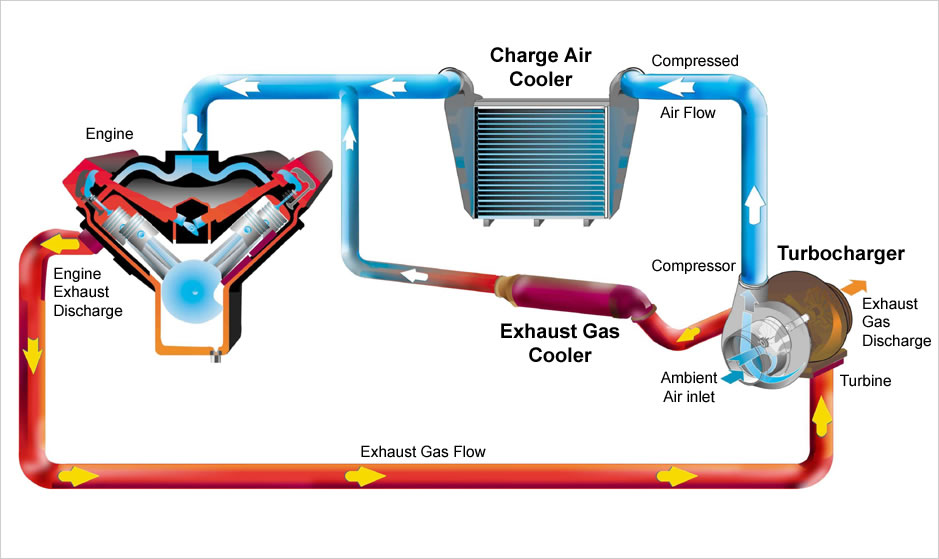
Sigue el siguiente proceso

  1. La entrada de aire del motor aspira aire frío y lo envía al compresor.
  2. El compresor comprime el aire entrante y lo calienta. Luego expulsa el aire caliente.
  3. El aire caliente se enfría al pasar por el intercambiador de calor y entra en la entrada de aire del cilindro.
  4. El aire frío arde dentro de la cámara de combustión a un ritmo más rápido debido a que transporta más oxígeno.
  5. Debido a que se quema más combustible, la producción de energía será mayor y más rápida y el motor podrá enviar más potencia a las ruedas.
  6. Los gases residuales calientes saldrán de la cámara y pasarán por la turbina en la salida de escape.
  7. La turbina gira a alta velocidad y también hace girar el compresor, ya que ambos están montados en el mismo eje.
  8. Los gases de escape salen del coche por el tubo de escape. Gastan menos energía que un motor sin turbocompresor.

TIPOS DE TURBOCOMPRESOR

  1. Turbo único

Los turbocompresores individuales por sí solos tienen una variabilidad ilimitada. Diferenciar el tamaño de la rueda del compresor y la turbina dará lugar a características de par completamente diferentes. Los turbos grandes generarán una alta potencia en la gama alta, pero los turbos más pequeños proporcionarán un mejor gruñido en las bajas ya que giran más rápido. También hay turbos simples con cojinetes de bolas y cojinetes lisos. Los rodamientos de bolas proporcionan menos fricción para que giren el compresor y la turbina, por lo que son más rápidos de enrollar (al tiempo que aumentan los costos).

Ventajas

  • Una forma rentable de aumentar la potencia y la eficiencia de un motor.
  • Simple, generalmente la más fácil de instalar de las opciones de turbocompresor.
  • Permite utilizar motores más pequeños para producir la misma potencia que los motores de aspiración natural más grandes, lo que a menudo puede eliminar peso.

Desventajas

  • Los turbos simples tienden a tener un rango de RPM efectivas bastante estrecho. Esto hace que el tamaño sea un problema, ya que tendrás que elegir entre un buen par a bajas revoluciones o una mejor potencia a altas revoluciones.
  • La respuesta del turbo puede no ser tan rápida como las configuraciones turbo alternativas.
  1. Twin Turbo

Al igual que con los turbocompresores simples, existen muchas opciones cuando se utilizan dos turbocompresores. Podría tener un solo turbocompresor para cada bancada de cilindros (V6, V8, etc.). Alternativamente, se podría usar un solo turbocompresor para bajas RPM y pasar a un turbocompresor más grande para altas RPM (I4, I6, etc.). Incluso podría tener dos turbos de tamaño similar, donde uno se usa a bajas RPM y ambos a altas RPM. En los BMW X5 M y X6 M se utilizan turbos Twin-Scroll, uno a cada lado del V8.

Ventajas

  • Para los turbos gemelos paralelos en motores en forma de “V”, los beneficios (y los inconvenientes) son muy similares a las configuraciones de un solo turbo.
  • Para turbos secuenciales o usando un turbo a bajas RPM y ambos a altas RPM, esto permite una curva de torsión mucho más amplia y plana. Mejor par a bajas revoluciones, pero la potencia no disminuirá a altas RPM como con un pequeño turbo único.

Desventajas

  • Costo y complejidad, ya que casi se han duplicado los componentes del turbo.
  • Existen formas más ligeras y eficientes de lograr resultados similares (como se analiza más adelante).
  1. Turbo de doble desplazamiento

Un turbo funciona con gases de escape que se redirigen para hacer girar las palas de la turbina y forzar el ingreso de aire al motor. Ahora, los cilindros de un motor se disparan en secuencia, lo que significa que los gases de escape ingresan al turbo en pulsos. Como probablemente puedas imaginar, estos pulsos pueden superponerse e interferir fácilmente entre sí al alimentar el turbo, y un turbocompresor de doble entrada resuelve este problema mediante el uso de una carcasa de turbina de entrada dividida y un colector de escape específico que empareja los cilindros correctos con cada uno. Desplazarse. En un vehículo de cuatro cilindros, puede tener el primer y cuarto cilindros alimentando un scroll, y dos y tres alimentando otro. Esto significa que hay menos superposición de pulsos y menos retraso.

Ventajas

  • Se envía más energía a la turbina de escape, lo que significa más potencia.
  • Es posible obtener un rango más amplio de RPM de impulso efectivo en función de los diferentes diseños de desplazamiento.
  • Es posible lograr una mayor superposición de válvulas sin obstaculizar la evacuación del escape, lo que significa más flexibilidad de ajuste.

Desventajas

  • Requiere una disposición del motor y un diseño de escape específicos (por ejemplo: I4 y V8, donde se pueden alimentar 2 cilindros a cada espiral del turbo, a intervalos iguales).
  • Costo y complejidad frente a los turbos simples tradicionales.
  1. Turbocompresor de geometría variable (VGT)

Un turbo de geometría variable (VGT) es una solución de energía costosa y compleja que prevalece especialmente en los motores diésel. Un VGT tiene un anillo de paletas de forma aerodinámica en la carcasa de la turbina que puede alterar su relación área-radio para que coincida con las revoluciones del motor. A bajas revoluciones, la relación área-radio crea más presión y velocidad para acelerar el turbo de manera más efectiva. A mayores revoluciones, la relación aumenta para dejar entrar más aire. El resultado es un rango de impulso más amplio y menos retraso.

Ventajas

  • Curva de torsión amplia y plana. Turbocompresor eficaz en un rango de revoluciones muy amplio.
  • Requiere solo un turbo, lo que simplifica una configuración de turbo secuencial en algo más compacto.

Desventajas

  • Normalmente sólo se utiliza en aplicaciones diésel donde los gases de escape son más bajos para que las paletas no se dañen con el calor.
  • Para las aplicaciones de gasolina, el costo normalmente las mantiene fuera, ya que se deben utilizar metales exóticos para mantener la confiabilidad. La tecnología se ha utilizado en el Porsche 997, aunque existen muy pocos motores de gasolina VGT debido al costo asociado.
  1. Turbocompresor variable de doble entrada

Un turbo variable de doble desplazamiento combina un VGT con una configuración de doble desplazamiento, por lo que a bajas revoluciones, uno de los desplazamientos se cierra por completo, forzando todo el aire hacia el otro. Esto da como resultado una buena respuesta del turbo y potencia a bajas revoluciones. A medida que acelera, se abre una válvula para permitir que entre aire en la otra espiral (este es un proceso completamente variable, lo que significa que la válvula se abre en pequeños incrementos), se obtiene un buen rendimiento de alta gama. Obtienes el tipo de rendimiento con un solo turbo que normalmente solo podrías obtener con una configuración de doble turbo.

Ventajas

  • Significativamente más baratos (en teoría) que los VGT, lo que constituye un argumento aceptable para el turbocompresor de gasolina.
  • Permite una curva de torsión amplia y plana.
  • Diseño más robusto que un VGT, dependiendo de la selección del material.

Desventajas

  • Costo y complejidad frente al uso de un solo turbo o el tradicional doble desplazamiento.
  • Se ha jugado con esta tecnología antes (por ejemplo: válvula de carrete rápido) pero no parece tener éxito en el mundo de la producción. Es probable que existan desafíos adicionales con la tecnología.
  • Turbocompresores eléctricos

Un avance muy reciente es la introducción de turbos con compresores eléctricos. Un ejemplo es el propulsor de BorgWarner, que es un compresor accionado eléctricamente. El compresor proporciona un impulso instantáneo al motor hasta que el turbocompresor se ha acelerado lo suficiente. Se puede encontrar una versión similar de esto en el SQ7 de Audi. Con el impulso instantáneo, el retraso se convierte en cosa del pasado, pero nuevamente, el sistema es costoso y complejo. Un compresor necesita un motor, que a su vez necesita ser alimentado, por lo que este no es un sistema sencillo de implementar.

Ventajas

  • Al conectar directamente un motor eléctrico a la rueda del compresor, el retraso del turbo y la cantidad insuficiente de gases de escape se pueden eliminar virtualmente haciendo girar el compresor con energía eléctrica cuando sea necesario.
  • Conectando un motor eléctrico a la turbina de escape se puede recuperar la energía desperdiciada (como se hace en la Fórmula 1).
  • Un rango de RPM efectivo muy amplio con par uniforme en todo momento.

Desventajas

  • Costo y complejidad, ya que ahora debe tener en cuenta el motor eléctrico y asegurarse de que permanezca frío para evitar problemas de confiabilidad. Esto también se aplica a los controladores agregados.
  • El embalaje y el peso se convierten en un problema, especialmente con la adición de una batería a bordo, que será necesaria para suministrar suficiente energía al turbo cuando sea necesario.
  • Los VGT o twin-scrolls pueden ofrecer beneficios muy similares (aunque no al mismo nivel) por un costo significativamente menor.

Refrigeración por Agua VS Refrigeración por aire

El sistema de refrigeración del motor de un vehículo sirve no sólo para mantener el motor frío, sino también para mantener su temperatura lo suficientemente cálida como para garantizar un funcionamiento eficiente y limpio.

Los componentes del sistema incluyen un radiador para disipar el calor, un ventilador o ventiladores para garantizar un flujo de aire adecuado para enfriar el radiador, una válvula de termostato que se abre cuando se alcanza la temperatura de funcionamiento deseada y una bomba de agua (o bomba de refrigerante) para hacer circular el refrigerante a través del motor, mangueras y otros componentes.

La mayoría de los vehículos ahora emplean un tanque de expansión que permite que el refrigerante se expanda y salga del circuito de enfriamiento cuando está caliente y regrese cuando se apaga el automóvil y el motor se enfría.
El sistema de refrigeración también incorpora elementos del sistema de ventilación del habitáculo, porque el calor del motor se utiliza para calentar el interior del coche.

Mientras está en marcha, un motor produce continuamente calor y lo convierte en energía.
Este calor se obtiene quemando combustible en el motor.
Pero como todos sabemos, no existe ningún motor en el mundo que sea 100% eficiente.
Siempre hay cierta cantidad de energía térmica que se desperdicia. Si no transmitimos esta energía térmica a la atmósfera, este calor sobrecalentará el motor.
Este sobrecalentamiento provocará que el motor se atasque. Cuando el motor se atasca, debido al exceso de calor, el pistón se funde dentro del cilindro.
Para evitar este problema de sobrecalentamiento, un automóvil cuenta con un sistema de enfriamiento del motor.

Un sistema de refrigeración del motor es un sistema integrado con los motores. Elimina el exceso de calor del motor con la ayuda de un fluido que fluye.
Este fluido puede ser aire o agua.

O podemos decir que hay dos tipos de sistemas de refrigeración.

  1. Sistema de refrigeración líquida o indirecta.
  2. Sistema de refrigeración por aire o directo

SISTEMA DE ENFRIAMIENTO LÍQUIDO O INDIRECTO

En un sistema de refrigeración líquida, un motor está rodeado de camisas de agua. Con la ayuda de una bomba, esta agua circula en esta camisa de agua.
El agua que fluye por estas camisas elimina el calor del motor. Esta agua caliente luego fluye a través de un radiador, donde se enfría gracias al calor frío que pasa a través de un ventilador.
En este sistema, el agua toma calor del motor y el aire la enfría y luego vuelve a circular hacia el motor.
Este es un proceso de enfriamiento indirecto, donde el enfriamiento real, que es el aire, no enfría directamente el sistema. El aire enfría el agua y el agua enfría el motor.
El sistema de refrigeración líquida o indirecta se utiliza principalmente en motores grandes, como los de coches y camiones.

Ventajas

  1. El diseño compacto de los motores.
  2. Proporciona un enfriamiento uniforme al motor.
  3. El motor se puede instalar en cualquier ubicación del vehículo. No es necesario instalar un motor en la parte delantera.
  4. Se puede utilizar tanto en motores pequeños como grandes.

Limitaciones

  1. Aquí la camisa de agua se convierte en una parte adicional del motor.
  2. La circulación del agua consume energía, lo que reduce la eficiencia del motor.
  3. En caso de falla del sistema de enfriamiento, el motor podría sufrir daños graves.
  4. El costo del sistema es considerablemente alto.
  5. Requiere mantenimiento de rutina y, por lo tanto, supone una carga adicional de costes de mantenimiento.

SISTEMA DE ENFRIAMIENTO DIRECTO O AIRE

En un sistema de refrigeración directa, un motor se enfría directamente con la ayuda del aire que fluye a través de él. Es el mismo sistema de refrigeración que se utiliza para enfriar los motores de nuestras bicicletas.
Como podemos ver aquí, el aire está en contacto directo con el motor, de ahí que también se le conozca como sistema de refrigeración directa.
El sistema de refrigeración por aire se utiliza para motores pequeños, como el de bicicletas y cortadoras de césped, etc.

Ventajas

  1. El diseño del motor se vuelve más sencillo.
  2. La reparación es fácil en caso de daños.
  3. La ausencia de un sistema de refrigeración voluminoso facilita el mantenimiento del sistema.
  4. No hay peligro de fugas de refrigerante.
  5. El motor no sufre problemas de congelación.
  6. El peso del sistema es menor.
  7. Es una unidad autónoma, ya que no requiere radiador, cabezal, tanques, etc.
  8. La instalación del sistema enfriado por aire es sencilla.

Limitaciones

  1. Es aplicable únicamente a motores pequeños y medianos.
  2. Sólo se puede utilizar en lugares donde la temperatura ambiente sea más baja.
  3. El enfriamiento no es uniforme.
  4. Temperatura de trabajo más alta en comparación con los motores refrigerados por agua.
  5. Produce más ruido aerodinámico.
  6. El consumo específico de combustible es ligeramente mayor.
  7. Reducir las relaciones de compresión máximas permitidas.
  8. El ventilador, si se utiliza, consume casi el 5% de la energía generada por los motores.

Características de un sistema de refrigeración de motor eficiente

A continuación se presentan dos características principales de un sistema de refrigeración de motor eficiente.

  1. Debe ser capaz de eliminar aproximadamente el 30% del calor generado en el motor manteniendo una temperatura de trabajo óptima en el motor.
  2. Debe eliminar el calor a un ritmo más rápido cuando el motor está caliente y eliminar el motor a un ritmo lento cuando está frío.

¿Qué significan las letras que tienen los rines ya sea en su cara interior o exterior?

JWL» (Japan Light Wheel Alloy) es una compilación de estándares definidos por el gobierno japonés para garantizar la seguridad del vehículo para las ruedas de aluminio. Cada rueda puesta al mercado debe ser probada para cumplir con los estándares de JWL antes de que una rueda pueda ser lanzada al mercado en Japón.

Estas normas son generalmente aceptadas en todo el mundo como aceptables para la mayoría de las condiciones de la carretera. Ése es porqué usted verá estas marcas en el europeo y otras ruedas del país asiático.

Japón Light Alloy Wheel Association, manteniendo un estrecho contacto con sus compañías miembro, realiza estudios de investigación y técnicos relacionados con la fabricación, comercialización y distribución de llantas de aleación ligeras para automóviles.

Estas actividades también incluyen el mercado y la investigación técnica dirigida a desarrollar la nueva demanda para los productos de la industria más muchas otras actividades relacionadas.

Para lograr estos objetivos, la asociación alemana de la rueda de la aleación de Japón apunta mejorar calidad de la 
rueda de la aleación ligera del automóvil y promueve la responsabilidad de su producto en el mercado automotor-Después.

Los objetivos principales incluyen también lo siguiente:
Para mantener estándares de seguridad, apoya la norma técnica «JWL» y «JWL-T» y promueve el sistema de registro «JAWA» VIA.

JWL. 
Rueda de la aleación ligera de Japón. La norma técnica para las llantas de aleación ligera para automóvil de pasajeros 
aprobado por el Ministerio de Transporte (MOT).

No photo description available.

JWL-T. 
Japón Camión y autobús de la rueda de la aleación ligera. 
La norma técnica para las ruedas de disco de aleación ligera para camiones y autobuses aprobado por el Ministerio de Transporte (MOT).

VÍA. 
Sistema de Registro de la Asociación de Inspección de Vehículos. La marcación VIA sólo se puede grabar en la rueda si se registra en el Japan Light Alloy Automotive Wheel Testing Council después de estrictas pruebas de calidad realizadas por la instalación de pruebas autorizada sobre la adaptabilidad del 
estándar técnico JWL o JWL-T.

No photo description available.

JAWA 
Para establecer el orden del diseño de la rueda en nuestra industria, 
«JAWA» promueve Voluntary Wheel Design Protection Registration System.
«JAWA» también presta su apoyo a los esfuerzos para encontrar soluciones al sistema de reciclaje de materiales.

¿Cómo funciona la válvula EGR?

En los motores más modernos, el funcionamiento de la EGR se rige por la señal de los sensores de temperatura del motor, régimen del motor y carga de aceleración. En función de estos la ECU del coche comandará la EGR, abriéndola o cerrándola. Por norma general, las EGR están abiertas (metiendo gases quemados al motor) cuando circulamos con el motor caliente, a baja carga y a regímenes de motor bajos.

Si se cumplen los parámetros para la apertura de la EGR, veremos que esta se acciona de dos formas, según su naturaleza. Puede ser por un actuador de vacío o por un actuador eléctrico. Las segundas son las más eficaces y las que ahora equipan casi todos los vehículos, ya que permiten controlar mejor el grado de apertura de la válvula. Algunos vehículos equipan válvulas EGR refrigeradas por un intercambiador de calor que utiliza el refrigerante del motor. De esta forma, se reduce la temperatura de los gases a la hora de introducirlos en los cilindros y la producción de emisiones de NOx es todavía menor.

Cuando la válvula EGR está abierta en la cámara de combustión se mezclan los gases recirculados con los gases frescos de la admisión. En este caso los segundos son menores que si la válvula estuviese cerrada y por tanto en las explosiones se genera menos calor, de ahí la reducción de las emisiones de NOx.

Como no es difícil intuir, el funcionamiento la válvula EGR resta potencia al motor. Cuanto más frío sea el aire que entra al motor y más oxígeno tenga, más potencia tendrán las explosiones y por tanto, mejor será el rendimiento del vehículo. Por ese motivo, cuando demandamos mucha aceleración, la EGR permanece cerrada, para tener todas las prestaciones del motor.

Cómo comprobar el ajuste de las válvulas de la cabeza de motor?

No photo description available.

Las holguras de las válvulas son pequeñas brechas entre la parte superior de los vástagos de la válvula y la parte del mecanismo que presiona sobre ellos para abrirlas.

Compruebe las holguras en intervalos regulares según se especifique en el programa de mantenimiento del auto y ajústela de ser necesario. Restablezca la holgura cada vez que se saque la culata.

Antes de empezar, asegúrese de conocer el tipo de mecanismo de válvula que comúnmente se llama engranaje de válvula (montado en el motor) y su holgura. El manual del auto debería indicarle la holgura, pero si no es así, consulte con un distribuidor o en el manual de servicio del auto.

Primero debe saber el orden de encendido del motor, cuál es el cilindro Nº 1, cuáles son las válvulas de admisión y de escape, y que balancín o levas lo hace funcionar. Realice un plan con toda esta información en un papel.

Encuentre la holgura correcta para las válvulas de admisión y escape, y si éstas deberían ser ajustadas con el motor caliente o frío.

FIRING ORDER: ITS PURPOSE AND ORDER IN DIFFERENT NUMBERS OF CYLINDERS

The firing order is the sequence of power delivery of each cylinder in a multi-cylinder reciprocating engine. This is achieved by sparking of the spark plugs in a gasoline engine in the correct order, or by the sequence of fuel injection in a Diesel engine. When designing an engine, choosing an appropriate firing order is critical to minimizing vibration and achieving smooth running, for long engine fatigue life and user comfort, and heavily influences crankshaft design.

No photo description available.

The firing order of an engine is the sequence in which the power event occurs in the different cylinders. The firing order is designed to provide for balance and to eliminate vibration to the greatest extent possible. In radial engines, the firing order must follow a special pattern since the firing impulses must follow the motion of the crank throw during its rotation. In inline engines, the firing orders may vary somewhat, yet most orders are arranged so that the firing of cylinders is evenly distributed along the crankshaft.

No photo description available.

PURPOSE OF FIRING ORDER

These are some factors which must be considered before deciding the optimum firing order of an engine. 
• Engine vibrations
• Engine cooling 
• Development of back pressure.
• Engine balancing and
• Even flow of power.

No photo description available.

FIRING ORDERS OF VARIOUS NUMBER OF CYLINDERS

1. 3-cylinder

Firing order
1-2-3 Saab two-stroke engine
1-3-2 BMW K75 engine

2. 4-cylinder

Firing order
• 1-3-4-2 Most straight-4s, Ford Taunus V4 engine
• 1-2-4-3 Some English Ford engines, Ford Kent engine
• 1-3-2-4 Yamaha R1 crossplane
• 1-4-3-2 Volkswagen air cooled engine

3. 5-cylinder

Firing order
• 1-2-4-5-3 Straight-5, Volvo 850, Audi 100

4. 6-cylinder

Firing order
• 1-5-3-6-2-4 Straight-6, Opel Omega A
• 1-6-5-4-3-2 GM 3800 engine
• 1-2-3-4-5-6 GM 60-Degree V6 engine
• 1-4-2-5-3-6 Mercedes-Benz M104 engine
• 1-4-5-2-3-6 Chevrolet Corvair
• 1-4-3-6-2-5 Mercedes-Benz M272 engine, Volkswagen V6’s
• 1-4-2-6-3-5 Toyota HZ engine

5. 7-cylinder

Firing order
• 1-3-5-7-2-4-6 7-cylinder single row radial engine

6. 8-cylinder

Firing order
• 1-8-4-3-6-5-7-2 1988 Chrysler Fifth Avenue, Chevrolet Small-Block engine
• 1-8-7-2-6-5-4-3 GM LS engine, Toyota UZ engine
• 1-3-7-2-6-5-4-8 Porsche 928, Ford Modular engine, 5.0 HO
• 1-5-4-8-7-2-6-3 BMW S65
• 1-6-2-5-8-3-7-4 Straight-8
• 1-8-7-3-6-5-4-2 Nissan VK engine
• 1-5-4-2-6-3-7-8 Ford Windsor engine
• 1-5-6-3-4-2-7-8 Cadillac V8 engine 368, 425, 472, 500 only
• 1-5-3-7-4-8-2-6 Ferrari Dino V8 (F355)
• 1-2-7-8-4-5-6-3 Holden V8

7. 10-cylinder

• 1-10-9-4-3-6-5-8-7-2 Dodge Viper V10 
• 1-6-5-10-2-7-3-8-4-9 BMW S85

8. 12-cylinder

Firing order
• 1-7-5-11-3-9-6-12-2-8-4-10 Ferrari 456M GT V12
• 1-7-4-10-2-8-6-12-3-9-5-11 Lamborghini Diablo VT
• 1-4-9-8-5-2-11-10-3-6-7-12 Caterpillar Inc. 3412E
• 1-12-5-8-3-10-6-7-2-11-4-9 Audi VW Bentley W12 engine
• 1,12,7,6,3,10,11,2,5,8,9,4 Rolls-Royce Merlin
• 1,12,4,9,2,11,6,7,3,10,5,8 Lamborghini Aventador

9. 16-cylinder

Firing order
1-12-8-11-7-14-5-16-4-15-3-10-6-9-2-13 Cadillac V16 engine

10. 20-cylinder

Firing order
• 1-12-8-11-7-14-5-16-4-15-3-10-6-9-13-17-19-2-18-20 Cadillac V20 engine

No photo description available.

¿Qué es el sistema de suspensión y cómo funciona?

El sistema de suspensión de un automóvil es una de las partes más críticas de un automóvil. A menudo pasa desapercibido ya que su funcionamiento es silencioso. Pero sin suspensión es difícil imaginarse conduciendo un coche. Entonces, ¿para qué sirve un sistema de suspensión en un coche?

La función principal del sistema de suspensión en un automóvil es mantener el vehículo estable anulando las fuerzas externas. Aquí, las fuerzas externas no son más que las fuerzas que siente la carrocería del coche debido a los baches, baches, etc., en la carretera. Además, la suspensión mantiene el coche estable en las curvas y a altas velocidades y ofrece un manejo superior.

Un sistema de varillajes mecánicos, resortes y amortiguadores que se utiliza para conectar las ruedas al chasis se conoce como sistema de suspensión. Por lo general, realiza dos trabajos: controlar el manejo y el frenado del vehículo por razones de seguridad y mantener a los pasajeros cómodos frente a golpes, vibraciones, etc.

También ayuda a mantener la altura correcta del vehículo y la alineación de las ruedas. También controla la dirección del vehículo y debe mantener la rueda en una dirección perpendicular para su máximo agarre. La suspensión también protege el vehículo y el equipaje de daños y desgaste. El diseño de la suspensión delantera y trasera de un automóvil puede ser diferente.

COMPONENTES DEL SISTEMA DE SUSPENSIÓN

Un sistema de suspensión, independientemente de su tipo, tiene algunos componentes principales en común que son:

  1. Knuckle or Upright-

Es el componente del sistema de suspensión que está montado sobre el cubo de la rueda a través del cual las ruedas y la suspensión del vehículo se conectan entre sí mediante los enlaces provistos.
Se proporciona un muñón con el pivote central y los ángulos de avance que ayudan a las ruedas delanteras del vehículo a girar en dirección derecha o izquierda, lo que a su vez dirige el vehículo.
Una articulación proporciona alojamiento para el cojinete central sobre el cual gira el cubo de la rueda junto con la rotación de las ruedas.

  1. Links

Los varillajes son las conexiones rígidas que se utilizan en el sistema de suspensión para conectar el bastidor principal del vehículo con la articulación de las ruedas a través de sujetadores mecánicos.

Según el tipo de suspensión, los enlaces utilizados son de 3 tipos:

i. Horquillas o brazo en A
Es el tipo de varillaje mecánico que tiene la forma del alfabeto A, el extremo puntiagudo del brazo en A está sujeto al nudillo y los otros 2 extremos del brazo en A están sujetos al bastidor principal del vehículo.
En función de la aplicación del vehículo, se utiliza un brazo A simple o un brazo A doble.

ii. Eje macizo o eje vivo.
Es el tipo de varillaje que se utiliza para conectar el bastidor principal del vehículo con el muñón de la rueda, esta es la carcasa del eje sólido que soporta el peso total del vehículo, este tipo de varillaje se puede ver en camiones.

III. Múltiples enlaces-
En lugar de utilizar doble horquilla o varillaje de eje sólido, varios automóviles de alta gama están adoptando un tipo de suspensión de vínculo múltiple en el que se utilizan múltiples vínculos sólidos para conectar el bastidor principal del vehículo al muñón de la rueda.

  1. Amortiguadores o resortes.
No photo description available.

Son los componentes mecánicos flexibles que se utilizan para absorber los impactos proporcionados por las condiciones de la carretera y se colocan entre los varillajes (espoleta. Eje sólido, enlaces múltiples) y el bastidor principal de modo que el impacto de la carretera se minimice antes de transmitirse al bastidor principal de un vehículo.

Según la aplicación y el tipo de suspensión, los amortiguadores utilizados son de muchos tipos que son:

i. Amortiguador tipo resorte y amortiguador-
Es el tipo de amortiguador en el que se utiliza un pistón neumático o hidráulico conocido como amortiguador que proporciona amortiguación absorbiendo los impactos de la carretera.

Este amortiguador está rodeado por un resorte helicoidal de compresión que es una restricción mecánica elástica que se comprime cuando el golpe aplica fuerza y retrocede o recupera su forma y tamaño originales cuando se elimina la fuerza.

Se utiliza para mantener la superficie de contacto de los neumáticos con la carretera proporcionando rigidez (resistencia a la compresión), además mantiene el amortiguador en su longitud original después de absorber el impacto.

No photo description available.

Ballesta
Es el tipo de resorte en el que una serie de placas de metal dúctil llamadas láminas están dispuestas en un patrón especial, es decir, una sobre una en orden ascendente de su longitud, las láminas del amortiguador de láminas están pretensadas de tal manera que cuando el choque es transferidas por las ruedas, estas hojas pretensadas al ser dúctiles intentan recuperar su forma original, es decir, enderezarse. Por lo que el impacto es absorbido por las hojas.

Este tipo de amortiguador se puede ver fácilmente en camiones en la carretera en los que se utiliza un amortiguador de ballesta entre el eje sólido o vivo y el bastidor principal del vehículo.

Aire
Es el último tipo de amortiguador que se puede ver fácilmente en los autobuses Volvo; en los amortiguadores de resorte neumático la amortiguación del impacto es una función de la compresión del aire, lo que significa que se utiliza aire como amortiguador.
El aire necesario para diferentes condiciones de carga es controlado y monitoreado por la unidad de control eléctrico del vehículo.

TIPOS DE SISTEMA DE SUSPENSIÓN

1) SISTEMA DE SUSPENSIÓN INDEPENDIENTE

Este sistema significa que la suspensión está configurada de tal manera que permite que las ruedas del lado izquierdo y derecho del vehículo se muevan verticalmente de forma independiente hacia arriba y hacia abajo mientras se conduce sobre una superficie irregular. Una fuerza que actúa sobre una sola rueda no afecta a la otra ya que no existe ningún vínculo mecánico entre los dos cubos del mismo vehículo. En la mayoría de los vehículos se emplea en las ruedas delanteras.
Este tipo de suspensión suele ofrecer una mejor calidad de marcha y manejo debido a que tiene menos peso no suspendido. La principal ventaja de la suspensión independiente es que requiere menos espacio, proporciona una maniobrabilidad más fácil, peso reducido, etc. Ejemplos de suspensión independiente son

No photo description available.

i. Double Wishbones

It is an independent suspension system design using two wishbone-shaped arms(called A-ARM in USA and WISHBONE in the UNITED KINGDOM)to locate the wheel. Each wishbone or arm has two mounting points to the chassis and one joint at the knuckle. The angle movements of the compressing and rebounding wheels can be managed by using arms of unequal length.
The main advantage of the double-wishbone suspensions is that they allow easy adjustments of camber, toe and other properties. This type of suspension also provides increasing negative camber gain all the way to full jounce travel. On the other hand, it takes more space and is slightly more complex than the other system like Macpherson strut. It also offers less design choice.

ii. MacPherson Strut

Opción de la suspensión de doble horquilla. La principal ventaja del MacPherson es que todas las piezas que proporcionan la suspensión y el control de las ruedas se pueden combinar en un solo conjunto.

Facilita la instalación en motor transversal. Este diseño es muy popular debido a su sencillez y bajo coste de fabricación. La desventaja es que es más difícil aislar del ruido de la carretera. Para ello es necesario un soporte de puntal superior, que debe estar lo más desacoplado posible. También requiere una mayor altura libre.

2) SISTEMA DE SUSPENSIÓN DEPENDIENTE

EN Suspensión dependiente hay un enlace rígido entre las dos ruedas del mismo eje. Una fuerza que actúa sobre una rueda afectará a la rueda opuesta. Por cada movimiento de la rueda provocado por la carretera, las irregularidades afectan también a la rueda acoplada.
Se emplea principalmente en vehículos pesados. Puede soportar golpes con mayor capacidad que la suspensión independiente. Ejemplo de este sistema es

I. Eje macizo.
Un eje macizo o un eje de viga es un tipo de suspensión dependiente. Se utiliza principalmente en ruedas traseras en las que el eje trasero está soportado y ubicado por dos ballestas. El movimiento vertical de una rueda influye en la otra. Son sencillos y económicos de fabricar.
Son tan rígidos que no hay cambios en el ancho de vía, la convergencia y la inclinación en un bache lleno, lo que ayuda a reducir el desgaste de los neumáticos. La principal desventaja es que la masa de la viga está incluida en el peso no suspendido del vehículo, lo que da como resultado una baja calidad de marcha. La capacidad para tomar curvas también es pobre debido al ángulo de caída cero.

3) SISTEMA SEMIINDEPENDIENTE

Este tipo de sistema tiene características tanto de suspensión dependiente como independiente. En la suspensión semiindependiente, las ruedas se mueven entre sí como en la suspensión independiente, pero la posición de una rueda tiene algún efecto sobre la otra. Esto se hace girando las piezas de suspensión. Ejemplo de semiindependiente es

i. Haz giratorio
La suspensión de viga de torsión también se conoce como eje de viga de torsión. Estos se basan principalmente en miembros en forma de C o H. La viga transversal en forma de H mantiene unidos los dos brazos de arrastre y proporciona rigidez a la suspensión.
Se utiliza principalmente en la rueda trasera de los coches. Es muy favorable por su bajo coste y es muy duradero. Tiene un diseño sencillo y es muy ligero. Pero, por otro lado, el ángulo de caída es limitado y la rigidez del balanceo tampoco es muy fácil. Las características de los dedos pueden ser inadecuadas.

¿Qué son los frenos de disco y cómo funcionan?

Los rotores de freno de los frenos de disco giran con las ruedas y las pastillas de freno, que están instaladas en las pinzas de freno, sujetan estos rotores para detener o desacelerar las ruedas. Las pastillas de freno que empujan contra los rotores generan fricción, que transforma la energía cinética en energía térmica.

Esta energía térmica genera calor, pero como los componentes principales están expuestos a la atmósfera, este calor se puede difundir de manera eficiente. Esta propiedad de disipación de calor reduce el desvanecimiento de los frenos, que es el fenómeno en el que el calor influye en el rendimiento de frenado. Otra ventaja de los frenos de disco es su resistencia a la pérdida de agua, que se produce cuando el agua en los frenos reduce significativamente la fuerza de frenado. Cuando el vehículo está en movimiento, el rotor gira a altas velocidades y este movimiento de rotación descarga el agua de los propios rotores, lo que da como resultado una fuerza de frenado estable.

CONSTRUCCIÓN

El rotor de freno (disco) que gira con la rueda, se sujeta mediante pastillas de freno (material de fricción) montadas en la pinza desde ambos lados con presión del pistón (mecanismo de presión) y desacelera la rotación del disco, desacelerando así y detener el vehículo.

  1. Rotor:
    Disco circular atornillado al cubo de la rueda que gira con la rueda. Los rotores suelen estar hechos de hierro fundido o acero; sin embargo, algunos coches de muy alta gama utilizan un rotor cerámico de carbono. Los rotores pueden tener ranuras o perforaciones para una mejor disipación del calor.
  2. Pastillas de freno:
    El componente que empuja hacia el rotor, creando la fricción que frena y detiene un automóvil. Presentan una parte metálica llamada zapato y un forro que se fija al zapato. El revestimiento es lo que realmente entra en contacto con el rotor y se desgasta con el uso. Los revestimientos están hechos de diferentes materiales y se dividen en tres categorías: orgánicos, semimetálicos y cerámicos. El material del revestimiento elegido afectará la duración de la vida útil de los frenos, la cantidad de ruido que se escucha cuando se aplican los frenos y la rapidez con la que los frenos detienen el automóvil.
  3. Pistón:
    Cilindro conectado al sistema hidráulico del freno. El pistón es lo que mueve las pastillas de freno hacia el rotor cuando el conductor presiona el pedal del freno. Algunos sistemas de frenos tienen un solo pistón que mueve ambas pastillas, mientras que otros tienen dos pistones que empujan las pastillas de freno desde cada lado del rotor. Otros todavía tienen cuatro, seis o incluso ocho pistones para una mayor potencia de frenado, a expensas de un mayor costo y complejidad.
  4. Calibrador:
    Carcasa que se ajusta sobre el rotor y sostiene las pastillas y pistones de freno, además de contener conductos para el líquido de frenos. Hay dos tipos de pinzas de freno: flotantes (o deslizantes) y fijas. Las pinzas flotantes “flotan” sobre el rotor y solo tienen pistones en un lado. Cuando el conductor presiona los frenos, los pistones presionan las pastillas de freno de un lado hacia el rotor, lo que hace que la pinza se deslice de modo que las pastillas del lado de la pinza sin pistón también entren en contacto con el rotor. Las pinzas fijas están atornilladas en su lugar y, en su lugar, tienen pistones a ambos lados del rotor que se mueven cuando el conductor aplica los frenos. Las pinzas fijas aplican la presión de los frenos de manera más uniforme y se sujetan más firmemente al rotor; sin embargo, las pinzas flotantes se encuentran en la mayoría de los automóviles y son perfectamente adecuadas para la conducción diaria.
  5. Sensores:
    Algunos vehículos tienen frenos que contienen sensores integrados en las pastillas de freno que funcionan para indicarle al conductor cuando las pastillas están desgastadas. Otros sensores de freno intervienen en el sistema ABS del vehículo.
    Los frenos de disco se utilizan generalmente en turismos, pero debido a su rendimiento estable a velocidades más altas y a su resistencia al desgaste de los frenos, se están extendiendo gradualmente al segmento de vehículos comerciales, donde tradicionalmente se eligieron frenos de tambor por su vida útil más larga. Hay dos tipos de frenos de disco.
    El «freno de disco de pistón opuesto» tiene pistones en ambos lados del rotor de disco, mientras que el «freno de disco de tipo flotante» tiene un pistón en un solo lado. Los frenos de disco con pinza flotante también se denominan frenos de disco con pasador deslizante.

PRINCIPIO DE FUNCIONAMIENTO

Cuando el conductor pisa el pedal del freno, la potencia es amplificada por el servofreno (sistema servo) y convertida en presión hidráulica (presión de aceite) por el cilindro maestro. La presión llega a los frenos de las ruedas a través de un tubo lleno de aceite de frenos (líquido de frenos). La presión entregada empuja los pistones de los frenos de las cuatro ruedas. Los pistones, a su vez, presionan las pastillas de freno, que son un material de fricción, contra los rotores de freno que giran con las ruedas. Las pastillas sujetan los rotores desde ambos lados y desaceleran las ruedas, reduciendo así la velocidad y deteniendo el vehículo.

Cuando se presiona, el fluido a alta presión del cilindro maestro empuja el pistón hacia afuera.

  • El pistón empuja la pastilla de freno contra el disco giratorio.
  • Cuando la pastilla de freno interna toca el rotor, la presión del fluido ejerce más fuerza y la pinza se mueve hacia adentro y tira de la pastilla de freno hacia afuera hacia el disco giratorio y toca el disco.
  • Ahora ambas pastillas de freno están empujando el disco giratorio, se genera una gran cantidad de fricción entre las pastillas y el disco giratorio y ralentiza el vehículo y finalmente lo deja detener.
  • Cuando se suelta una pastilla de freno, el pistón se mueve hacia adentro y la pastilla de freno se aleja del disco giratorio. Y el vehículo vuelve a ponerse en marcha.

TIPOS DE FRENOS DE DISCO

Hay dos tipos de frenos de disco. Uno se llama «freno de disco de pistón opuesto» que tiene pistones en ambos lados del rotor de disco, y el otro es «freno de disco de tipo flotante» que tiene un pistón en un solo lado. Los frenos de disco de tipo flotante también se denominan frenos de disco de tipo pasador deslizante.

  1. Frenos de disco de pistón opuesto

El tipo de pistón opuesto es un freno de disco que tiene pistones a ambos lados de los rotores de disco.
El freno de disco de pistón opuesto presenta una fuerza de frenado estable así como un alto nivel de controlabilidad.
Las áreas barridas de las pastillas de freno se agrandan para aumentar la fuerza de frenado y aquí se prefieren los tipos de pistones opuestos. Esto se debe a su ventaja de que se puede aumentar el número de pistones para lograr una distribución uniforme de la presión sobre los rotores desde ambos lados. Dependiendo del tamaño de las pastillas de freno, existen varios tipos, incluido el tipo de 4 pistones que tiene dos pistones a cada lado para un total de cuatro, y el tipo de 6 pistones que tiene tres pistones a cada lado para un total de seis.

  1. Frenos de disco tipo flotante

El tipo flotante es un freno de disco que tiene un pistón en un solo lado y también se llama freno de disco de tipo deslizante.
En los frenos de disco de tipo flotante, el pistón empuja la pastilla de freno interna contra el rotor cuando se activan los frenos. Esto genera una fuerza de reacción que mueve la pinza junto con el pasador deslizante, empujando la pastilla exterior contra el rotor para sujetarlo por ambos lados.

Muchos frenos de disco de turismos son del tipo de pinza flotante, ya que este tipo tiene una construcción relativamente simple y liviana, lo que permite menores costos de fabricación.
Frenos de disco tipo flotante para vehículos comerciales.
Los frenos de disco se utilizan principalmente en turismos, pero debido a su rendimiento constante a velocidades más altas y a su resistencia al desgaste de los frenos, se están extendiendo gradualmente al segmento de vehículos comerciales, donde tradicionalmente se elegían los frenos de tambor por su resistencia al desgaste.

TIPOS DE ROTORES

  1. Rotores lisos
    Los rotores lisos se identifican por su superficie plana y lisa. Para la mayoría de los automóviles y camiones que circulan por la carretera, los rotores lisos son equipos originales (OE) debido a su versatilidad para muchas condiciones de conducción. El principal beneficio de los rotores lisos es que tienden a desgastarse de manera uniforme, lo que ayuda a que las pastillas de freno duren más. Si desea mantener el rotor suave pero aún así optar por una actualización, busque metal de primera calidad que absorba más calor.
  1. Rotores perforados o con hoyuelos
    Los rotores perforados se identifican por el patrón de orificios que se han perforado a lo largo de todo el disco del rotor. Los rotores con hoyuelos son similares, aunque en lugar de agujeros hay hoyuelos que se han perforado hasta el nivel de espesor mínimo del rotor, conservando más integridad estructural que un rotor completamente perforado. Estos tipos de rotor ayudan a las pastillas de freno a agarrar mejor el rotor, dándole más mordida inicial y aumentando la potencia de frenado.
    *Tenga en cuenta que los rotores perforados o con hoyuelos generalmente se encuentran en combinación con rotores ranurados.
  2. Rotores ranurados
    Los rotores ranurados se reconocen por las líneas talladas que se encuentran en el rotor. Estas ranuras talladas ayudan a enfriar el rotor durante el uso de alto rendimiento. También ayudan a eliminar la suciedad y otros residuos del disco y las pastillas de freno, lo que ayuda a mantener un contacto constante para un frenado más eficiente. Los rotores ranurados son perfectos para vehículos que requieren remolques pesados y frecuentes.
  3. Rotores perforados/con hoyuelos y ranurados
    Los rotores que están perforados (o con hoyuelos) y ranurados, si bien son efectivos, son mejores para las camionetas que desean una estética adicional, como aquellas con ruedas que tienen un diseño más abierto. No solo se verán geniales a través de una rueda abierta, sino que los orificios perforados ayudarán con una mordida inicial, mientras que las ranuras están diseñadas para eliminar el polvo y los residuos entre el rotor y la pastilla de freno.

MATERIALES DEL RÓTOR

Los rotores de freno pueden estar hechos de seis materiales diferentes, cada uno con sus propias ventajas. Echemos un vistazo a cada uno.

  1. Hierro fundido
    Esta es la definición misma de la vieja escuela cuando se trata de un rotor de freno. Son una o dos piezas y hace el trabajo. De hecho, es el material más común para los rotores de freno. El diseño correcto (generalmente de dos piezas) puede funcionar incluso bien en un vehículo de alto rendimiento. Sin embargo, también es la opción más pesada, lo que afecta el peso total de su automóvil y su manejo, ya que ese peso está a la altura de las ruedas delanteras.
  2. Acero
    El acero ha sido la elección de los corredores durante años porque un rotor de freno de acero es más delgado, pesa menos y soporta mejor el calor. La desventaja: los rotores de acero no son tan duraderos como otros, y los rotores deformados pueden provocar ruido y pulsaciones en el pedal al frenar.
  3. Acero en capas
    Colocar capas de láminas de acero juntas y laminarlas las hace resistentes a la deformación que se puede encontrar en un rotor de freno de acero recto. Es el favorito de los corredores que no quieren reemplazar y reparar frecuentemente el rotor del freno, pero actualmente los fabricantes solo se dirigen a los corredores profesionales y la producción es limitada, por lo que no es muy común en aplicaciones de vehículos de pasajeros.
  4. Aluminio
    Los rotores de freno de aluminio disipan el calor rápidamente, pero también se derriten a una temperatura más baja que otras opciones. El aluminio es el favorito de las motocicletas, que pesan menos y son más suaves para los rotores al frenar que un automóvil, camión o SUV pesado.
  5. Alto contenido de carbono
    Son hierro, pero con mucho carbono mezclado. Pueden absorber mucho calor y disiparlo rápidamente. El contenido metálico ayuda al rotor a evitar grietas bajo tensión elevada y también se reducen el ruido y la vibración de los frenos. El único inconveniente es el precio, que es mucho más alto que el de hierro puro o el de aluminio.
  6. Cerámica
    ¿Cuál es tu superdeportivo favorito? ¿Ferrari? ¿Porsche? ¿Lamborghini? Lo más probable es que tenga rotores de freno cerámicos. Ofrecen la mayor capacidad calorífica (85 por ciento más que el hierro fundido) y una disipación superior, y mantienen una fuerza y presión más consistentes a medida que aumenta la temperatura de los rotores. La cerámica es el rotor de freno de mayor rendimiento disponible en la actualidad.

VENTAJAS Y DESVENTAJAS

Ventajas

  1. Es más ligero que los frenos de tambor.
  2. Tiene mejor enfriamiento (porque la superficie de frenado está directamente expuesta al aire)
  3. Ofrece mejor resistencia a la decoloración.
  4. Proporciona una distribución uniforme de la presión.
  5. La sustitución de las pastillas de freno es sencilla.
  6. Por diseño, son frenos autoajustables.

Desventajas

  1. Es más costoso que los frenos de tambor.
  2. Se requiere una mayor presión en el pedal para detener el vehículo. Este sistema de frenos está instalado con refuerzo de vacío.
  3. No hay acción servo presente.
  4. Es difícil colocar un accesorio de estacionamiento adecuado.

Tipos de transmisiones automáticas

  1. Transmisión automática tradicional

También se conoce como transmisión automática, transmisión de n velocidades o automática de convertidor de par, este es el tipo estándar de transmisión automática que se encuentra en la mayoría de los automóviles en estos días. A diferencia de una caja de cambios manual, no utiliza embrague para cambiar de marcha. En cambio, un acoplamiento de fluido hidráulico o un convertidor de par hacen este trabajo. Se conecta a la Unidad de Control Electrónico del motor y permite un control preciso del vehículo.

Es un tipo de transmisión que cambia automáticamente las relaciones de transmisión a medida que el vehículo se mueve. Los beneficios de un AT se centran en brindar a los conductores la libertad de cambiar de marcha manualmente. Otras ventajas incluyen un control del motor suave y preciso. Tenga en cuenta que AT se puede encontrar en muchos vehículos que no son MT.

Los coches automáticos funcionan sin problemas, pero el cambio de marchas no es rápido todo el tiempo, lo que les valió el nombre de «slushbox». Sin embargo, la impresión ha ido cambiando gracias a algunos modelos de transmisión brillantes, como la ZF de 8 velocidades, que se encuentra en muchos coches, desde Jaguars hasta BMW.

  1. Transmisión manual automatizada

También conocida como transmisión semiautomática (SAT) o cajas de cambios con paletas de cambio, una transmisión semiautomática es un tipo de transmisión automática en la que el conductor realiza cambios de marcha similares a una transmisión manual. Sin embargo, no tiene embrague a diferencia de un MT y utiliza equipos electrónicos como sensores, actuadores y procesadores para simular el cambio manual y hacer que el cambio de marcha sea preciso y suave.

Este tipo de transmisión automática utiliza una configuración normal de embrague y engranaje, pero automatiza la acción mediante el uso de sensores, actuadores, procesadores y sistemas neumáticos.

Los coches con esta transmisión ofrecen un mejor rendimiento en las carreteras. No se recomiendan para conducir en ciudad porque los motores se sienten entrecortados al acelerar con fuerza.

  1. Transmisión continuamente variable (CVT)

Una transmisión continuamente variable o CVT es técnicamente otro tipo de transmisión automática. Sin embargo, no utiliza engranajes mecánicos a diferencia de un AT y, en su lugar, utiliza correas o poleas para permitir cambios de marcha fluidos en función de las raciones y de la velocidad del motor. El diseño compacto y la aceleración continua son algunas de las ventajas de una CVT, mientras que la sensación y el costo del motor son algunas de sus desventajas.

Permite cambios de marcha fluidos con numerosas gamas de relaciones y facilita que el motor gire a las RPM (velocidad) máximas.

Existen dos tipos más de CVT. La CVT hidrostática utiliza motores hidrostáticos y bombas de desplazamiento variable para transferir potencia al motor. Por otro lado, las CVT Toroidales utilizan discos y rodillos de potencia para este fin.
La transmisión permite que el motor funcione con la máxima eficiencia con una aceleración fluida. Es bueno para ahorrar combustible y la reparación y el mantenimiento no son costosos. Sin embargo, el motor genera mucho ruido al acelerar y bajo carga. Muchos modelos utilizan esta caja de cambios y algunos de los favoritos del público son Chevrolet Spark, Ford C-Max, Nissan Sentra y más.

  1. Transmisión de doble embrague (DCT)

Otro tipo de transmisión automática es el sistema de transmisión de doble embrague o DCT. También conocida como transmisión de doble embrague o transmisión de doble embrague, no tiene un convertidor de par e implica principalmente el uso de dos embragues separados para conjuntos de marchas pares e impares, lo que permite un cambio fluido a marchas más altas y más bajas. Tampoco tiene pedal de embrague y, en su lugar, una computadora acciona ambos embragues. Por tanto, ofrece la facilidad de un AT con el rendimiento de un MT.

Es un híbrido de transmisión automática y manual. No hay convertidor de par en DCT. Utilizará dos ejes separados para cambiar de marcha, uno para las marchas impares y otro para las pares. Ambos ejes tienen su propio embrague.

Puedes cambiar a una marcha más alta o más baja en una fracción de segundo y la transición de automático a manual también es perfecta. Sin embargo, las cajas de cambios DCT no pueden escapar a las quejas de embragues ruidosos, chirridos y cambios bruscos.

  1. Caja de cambios de cambio directo (DSG)

Es uno de los tipos de transmisión automática que funciona igual que una caja de cambios manual. Sin embargo, es diferente de la operación manual en el sentido de que utiliza un convertidor de par en lugar de un pedal de embrague, tiene la opción de cambio automático y no permite que el conductor tenga control total sobre las marchas.

Una transmisión Tiptronic le da al conductor la opción de conducir en modo automático o manual. Introducida por Porsche en los años 90 y adoptada poco después por otros fabricantes, este tipo de transmisión automática no tiene embrague pero, cuando se utiliza en modo manual, permite la selección directa de marchas ascendentes y descendentes mediante levas detrás del volante o utilizando la propia palanca de cambios. . Cuando se utiliza en modo automático, la computadora realiza el cambio de marcha.

Lo único de esta unidad es que tiene la opción de anular el modo automático. Significa que puede conducir su automóvil en modo automático y además poder cambiar al modo manual cuando sea necesario, como subir una colina o bajar por una carretera empinada.

Los automóviles que utilizan esta unidad tienen una característica de seguridad incorporada para que cualquier error del conductor no provoque daños en la caja de cambios. Varios fabricantes utilizan este tipo de transmisión automática, pero se vio por primera vez en el Porsche 911 (en 1990) y luego fue adoptada por BMW y Chrysler.

IC ENGINE: COMPONENTS AND THEIR FUNCTIONS, TYPES AND TERMINOLOGY

It is an engine in which combustion of fuel take place inside the engine. When the fuel burns inside the engine cylinder, it generates a high temperature and pressure. This high-pressure force is exerted on the piston (A device which free to moves inside the cylinder and transmit the pressure force to crank by use of connecting rod), which used to rotate the wheels of vehicle. In these engines we can use only gases and high volatile fuel like petrol, diesel. These engines are generally used in automobile industries, generation of electric power etc.

Advantages of I.C. engine

 It has overall high efficiency over E.C. engine.
 These engines are compact and required less space.
 Initial cost of I.C. engine is lower than E.C. engine.
 This engine easily starts in cold because of it uses high volatile fuel.

COMPONENTS OF IC ENGINE

1. Cylinder block
Cylinder is the main body of IC engine. Cylinder is a part in which the intake of fuel, compression of fuel and burning of fuel take place. The main function of cylinder is to guide the piston. It is in direct contact with the products of combustion so it must be cooled. For cooling of cylinder, a water jacket (for liquid cooling used in most of cars) or fin (for air cooling used in most of bikes) are situated at the outer side of cylinder. At the upper end of cylinder, cylinder head and at the bottom end crank case is bolted. The upper side of cylinder is consisting a combustion chamber where fuel burns. To handle all this pressure and temperature generated by combustion of fuel, cylinder material should have high compressive strength. So it is made by high grade cast iron. It is made by casting and usually cast in one piece.

2. Cylinder head
The top end of the engine cylinder is closed by means of removable cylinder head. There are two holes or ports at the cylinder head, one for intake of fuel and other for exhaust. Both the intake and exhaust ports are closed by the two valves known as inlet and exhaust valve. The inlet valve, exhaust valve, spark plug, injector etc. are bolted on the cylinder head. The main function of cylinder head is to seal the cylinder block and not to permit entry and exit of gases on cover head valve engine. Cylinder head is usually made by cast iron or aluminum. It is made by casting or forging and usually in one piece.

3. Piston
A piston is fitted to each cylinder as a face to receive gas pressure and transmit the thrust to the connecting rod. It is a prime mover in the engine. The main function of piston is to give tight seal to the cylinder through bore and slide freely inside the cylinder. Piston should be light and sufficient strong to handle gas pressure generated by combustion of fuel. So the piston is made by aluminum alloy and sometimes it is made by cast iron because light alloy piston expands more than cast iron so they need more clearances to the bore.

4. Piston rings
A piston must be a fairly loose fit in the cylinder so it can move freely inside the cylinder. If the piston is too tight fit, it would expand as it got hot and might stick tight in the cylinder and if it is too loose it would leaks the vapor pressure. To provide a good sealing fit and less friction resistance between the piston and cylinder, pistons are equipped with piston rings. These rings are fitted in grooves which have been cut in the piston. They are split at one end so they can expand or slipped over the end of piston. A small two stroke engine has two piston rings to provide good sealing but a four-stroke engine has an extra ring which is known as oil ring. Piston rings are made of cast iron of fine grain and high elastic material which is not affected by the working heat. Sometimes it is made by alloy spring steel.

5. Connecting rod
Connecting rod connects the piston to crankshaft and transmits the motion and thrust of piston to crankshaft. It converts the reciprocating motion of the piston into rotary motion of crankshaft. There are two end of connecting rod; one is known as big end and other as small end. Big end is connected to the crankshaft and the small end is connected to the piston by use of piston pin. The connecting rods are made of nickel, chrome, and chrome vanadium steels. For small engines the material may be aluminum.

6. Crankshaft
The crankshaft of an internal combustion engine receives the efforts or thrust supplied by piston to the connecting rod and converts the reciprocating motion of piston into rotary motion of crankshaft. The crankshaft mounts in bearing so it can rotate freely. The shape and size of crankshaft depends on the number and arrangement of cylinders. It is usually made by steel forging, but some makers use special types of cast-iron such as spheroidal graphitic or nickel alloy castings which are cheaper to produce and have good service life.

7. Engine bearing
Everywhere there is rotary action in the engine, bearings are needed. Bearings are used to support the moving parts. The crankshaft is supported by bearing. The connecting rod big end is attached to the crank pin on the crank of the crankshaft by a bearing. A piston pin at the small end is used to attach the rod to the piston is also rides in bearings. The main function of bearings is to reduce friction between these moving parts. In an IC engine sliding and rolling types of bearing used. The sliding type bearing which are sometime called bush is use to attach the connecting rod to the piston and crankshaft. They are split in order to permit their assembly into the engine. The rolling and ball bearing is used to support crankshaft so it can rotate freely. The typical bearing half is made of steel or bronze back to which a lining of relatively soft bearing material is applied.

8. Crankcase
The main body of the engine at which the cylinder are attached and which contains the crankshaft and crankshaft bearing is called crankcase. It serves as the lubricating system too and sometime it is called oil sump. All the oil for lubrication is placed in it.

9. Valves
To control the inlet and exhaust of internal combustion engine, valves are used. The number of valves in an engine depends on the number of cylinders. Two valves are used for each cylinder one for inlet of air-fuel mixture inside the cylinder and other for exhaust of combustion gases. The valves are fitted in the port at the cylinder head by use of strong spring. This spring keep them closed. Both valves usually open inwards.

10. Spark plug
It is used in spark ignition engine. The main function of a spark plug is to conduct a high potential from the ignition system into the combustion chamber to ignite the compressed air fuel mixture. It is fitted on cylinder head. The spark plug consists of a metal shell having two electrodes which are insulated from each other with an air gap. When high potential current supply to spark plug it jumping from the supply electrode and produces the necessary spark.

11. Injector
Injector is usually used in compression ignition engine. It sprays the fuel into combustion chamber at the end of compression stroke. It is fitted on cylinder head.

12. Manifold
The main function of manifold is to supply the air fuel mixture and collects the exhaust gases equally from all cylinder. In an internal combustion engine two manifold are used, one for intake and other for exhaust. They are usually made by aluminum alloy.

13. Camshaft
Camshaft is used in IC engine to control the opening and closing of valves at proper timing. For proper engine output inlet valve should open at the end of exhaust stroke and closed at the end of intake stroke. So to regulate its timing, a cam is use which is oval in shape and it exerts a pressure on the valve to open and release to close. It is drive by the timing belt which drives by crankshaft. It is placed at the top or at the bottom of cylinder.

14. Gudgeon pin or piston pin
These are hardened steel parallel spindles fitted through the piston bosses and the small end bushes or eyes to allow the connecting rods to swivel. It connects the piston to connecting rod. It is made hollow for lightness.

15. Pushrod
Pushrod is used when the camshaft is situated at the bottom end of cylinder. It carries the camshaft motion to the valves which are situated at the cylinder head.

16. Flywheel
A flywheel is secured on the crankshaft. The main function of flywheel is to rotate the shaft during preparatory stroke. It also makes crankshaft rotation more uniform.

TYPES OF I.C ENGINE

I.C. engine is widely used in automobile industries so it is also known as automobile engine. An automobile engine may be classified in many manners.

According to number of stroke:

1. Two stroke engine
In a two stroke engine a piston moves one time up and down inside the cylinder and complete one crankshaft revolution during single time of fuel injection. This type of engine has high torque compare to four stroke engine. These are generally used in scooters, pumping sets etc.

2. Four stroke engine
In a four stroke engine piston moves two times up and down inside the cylinder and complete two crankshaft revolutions during single time of fuel burn. This type of engines has high average compare to two stroke engine. These are generally used in bikes, cars, truck etc.

According to design of engine:

1. Reciprocating engine (piston engine)
In reciprocating engine the pressure force generate by combustion of fuel exerted on a piston (A device which free to move in reciprocation inside the cylinder). The piston starts reciprocating motion (too and fro motion). This reciprocating motion converts into rotary motion by use of crank shaft. So the crank shaft starts to rotate and make rotate the wheels of the vehicle. These are generally used in all automobile.

2. Rotary engine (Wankel engine)
In rotary engine there is a rotor which frees to rotate. The pressure force generated by burning of fuel is exerted on this rotor so the rotor rotate and starts to rotate the wheels of vehicle. This engine is developed by Wankel in 1957. This engine is not used in automobile in present days.

According to fuel used:

1. Diesel engine
These engines use diesel as the fuel. These are used in trucks, buses, cars etc.

2. Petrol engine
These engines use petrol as the fuel. These are used in bikes, sport cars, luxury cars etc.

3. Gas engine
These engines use CNG and LPG as the fuel. These are used in some light motor vehicles.

According to method of ignition:

1. Compression ignition engine
In these types of engines, there is no extra equipment to ignite the fuel. In these engines burning of fuel starts due to temperature rise during compression of air. So it is known as compression ignition engine.

2. Spark ignition engine
In these types of engines, ignition of fuel start by a spark, generated inside the cylinder by some extra equipment (Spark Plug). So it is known as spark ignition engine.

According to number of cylinder:

1. Single cylinder engine
In this type of engines have only one cylinder and one piston connected to the crank shaft.

2. Multi-cylinder engine
In this type of engines have more than one cylinder and piston connected to the crank shaft

According to arrangement of cylinder:

1. In-line engine
In this type of engines, cylinders are positioned in a straight line one behind the other along the length of the crankshaft.

2. V-type engine
An engine with two cylinder banks inclined at an angle to each other and with one crankshaft known as V-type engine.

3. Opposed cylinder engine
An engine with two cylinders banks opposite to each other on a single crankshaft (V-type engine with 180o angle between banks).

4. W-type engine
An engine same as V-type engine except with three banks of cylinders on the same crankshaft known as W-type engine.

5. Opposite piston engine
In this type of engine there are two pistons in each cylinder with the combustion chamber in the center between the pistons. In this engine, a single combustion process causes two power strokes, at the same time.

6. Radial engine
It is an engine with pistons positioned in circular plane around the central crankshaft. The connecting rods of pistons are connected to a master rod which, in turn, connected to the crankshaft.

According to air intake process:

1. Naturally aspirated
In this types of engine intake of air into cylinder occur by the atmospheric pressure.

2. Supercharged engine
In this type of engine air intake pressure is increased by the compressor driven by the engine crankshaft.

3. Turbocharged engine
In this type of engine intake air pressure is increase by use of a turbine compressor driven by the exhaust gases of burning fuel.

ENGINE TERMINOLOGY

1. Top dead center (T.D.C.)
In a reciprocating engine the piston moves to and fro motion in the cylinder. When the piston moves upper direction in the cylinder, a point at which the piston comes to rest or change its direction known as top dead center. It is situated at top end of cylinder.

2. Bottom dead center (B.D.C.)
When the piston moves in downward direction, a point at which the piston come to rest or change its direction known as bottom dead center. It is situated in bottom side of cylinder.

3. Stroke (L)
The maximum distance travel by the piston in single direction is known as stroke. It is the distance between top dead center and bottom dead center.

4. Bore (b)
The inner diameter of cylinder known as bore of cylinder.

5. Maximum or total volume of cylinder (Vtotal)
It is the volume of cylinder when the piston is at bottom dead center. Generally, it is measure in centimeter cube (c.c.).

6. Minimum or clearance volume of cylinder (Vclearance)
It is the volume of cylinder when the piston is at top dead center.

7. Swept or displace volume (Vswept)
It is the volume which swept by the piston. The difference between total volume and clearance volume is known as swept volume.

Swept volume = Total volume – Clearance volume

8. Compression ratio
The ratio of maximum volume to minimum volume of cylinder is known as the compression ratio. It is 8 to 12 for spark ignition engine and 12 to 24 for compression ignition engine.

Compression ratio = Total volume / Clearance volume

9. Ignition delay
It is the time interval between the ignition start (spark plug start in S.I. engine and inject fuel in C.I. engine) and the actual combustion starts.

10. Stroke bore ratio
Stroke bore ratio is the ratio of bore (diameter of cylinder) to length of stroke. It is generally equal to one for small engine and less than one for large engine.

Stroke bore ratio = inner diameter of cylinder / length of stroke

11. Mean effective pressure
The average pressure acting upon the piston is known as mean effective pressure. It is given by the ratio of the work done by the engine to the total volume of engine.

Mean effective pressure = Work done by engine / Total volume of cylinder

Sistema de carga: Componentes, funciones, operaciones y trucos de diagnostico

CHARGING SYSTEM: COMPONENTS, FUNCTIONS, WORKING PRINCIPLE AND DIAGNOSIS TIPS

The vehicle is equipped with many electrical devices to drive safely and comfortably. The vehicle requires electricity not only while driving but also while it stops.

Therefore, the vehicle has a battery for a power supply and a charging system to generate electricity by the engine running. The charging system supplies electricity to all the electrical devices and charges the battery.

The Charging system is an important part of the electrical system. It provides electrical current for the lights, the radio, the heater, the engines electrical systems, and other electrical accessories. It also maintains the batteries in a charged state, recharging them as necessary.

The charging system has three main components: the alternator, the voltage regulator, and the batteries.

The alternator generates electrical power to run accessories and to recharge the batteries. It is normally driven by a belt located off the crankshaft. Mechanical energy from the crankshaft is converted by the alternator into electrical energy for the batteries and accessories.
The voltage regulator acts as an electrical traffic cop to control the alternator output. It senses when the batteries need recharging, or when the vehicles electrical needs increase and adjust the alternator’s output accordingly.

The batteries are a reservoir of chemical electrical power. Their primary purpose is to crank the engine. They also supply power to vehicle accessories when the electrical load is too great for the alternator alone.

Three-phase alternating current

(1) When a magnet rotates within a coil, a voltage will be created between both ends of the coil. This will give rise to an alternating current.
(2) The relation between the current generated in the coil and the position of the magnet is as shown in the figure. The largest amount of current is generated when the N and S poles of the magnet are closest to the coil. However, the current flows in the opposite direction with each half-turn of the magnet. Current that forms a sine wave in this manner is called “single-phase alternating current”.

COMPONENTS AND FUNCTIONS

In general, the components of the charging system are composed of alternators and regulators. However, the charging system needs to add some additional components so that the electricity generated can be supplied to the battery and to all electrical loads safely and precisely. The component, consisting of;

1. Battery

The function of the battery is as a storage of electrical energy. Like a warehouse, the battery will store all the electrical energy generated by the alternator and then this stored electricity is removed when necessary.

2. Fuse and Fusible links

Fuse and fusible links have different functions even though have the same shape. The fusible link can be called as the main fuse which is placed near the battery positive terminal. The function of this fuse is to protect the entire electrical system of the car from excessive currents. Generally, the fusible link has a capacity of up to more than 60 Ampere.

While the function of the fuse is as the safety of a series of specific electrical wiring, in conventional charging system there are two fuses with the same capacity (it’s about 10-15 Ampere). A fuse is used as a voltage regulator fuse and another fuse is used to secure the CHG and Voltage relay.

3. CHG Lights

CHG lamp or commonly also called “charging warning light” is an indicator light to indicate the present failure of the charging system. When the ignition key ON then this light will light up normally, as well as when the engine life of this lamp should turn on, if it is dead then it could mean the charging system failure.

4. Ignition key

The ignition key works as a switch. The charging system will be activated automatically when the engine is running, but to generate a magnetic field on the rotor coil must be done by a switch.

The ignition switch is used as a switch to connect and disconnect power (positive battery current) from battery to rotor coil. When the ignition key is ON, then the electricity from the battery to the coil rotor will be connected. However, when the ignition key is turned OFF then the power supply will be cut off. So it is not possible the alternator generates electricity when the ignition key is OFF even the engine crankshaft rotates.

5. Regulator

The function of the regulator is to regulate the voltage generated by the alternator. Why should it be there? because the voltage generated by the alternator depends on the engine’s RPM. This means that if the engine RPM is low, the alternator voltage is also low, but if the engine RPM is high then the alternator voltage is also high.

The regulator will be used to keep the voltage generated by the alternator not exceeding 14 volts even if the engine run in high RPM. This voltage setting aims to protect the electrical components of the vehicle to prevents over-voltage.

There are two types of regulators, namely type or conventional type and type of IC. The point type/conventional uses two coils to adjust the alternator output voltage. While the IC Regulator uses an IC circuit (Integrated Circuit) to regulate the output voltage.

6. Altenator

The function of the alternator is to convert a partial engine’s rotating energy into electricity. The alternator input comes from the engine pulley connected through a V belt, the rotation of the rotor will cause the intersection of the magnetic force line with the stator coil so that the electrons flow on the stator coil.

The electricity in the stator coil is not directly connected to the battery, but it must pass through the diode bridge to rectify the current. This is done because the current in the stator coil is AC (Alternate Current).

7. Charging Wire

The function of the charging wire is to connect every component of the charging system, there are at least two types of wires: standard wire and B + wire. The standard wire has a small diameter like the car’s electrical wiring in general, the function of this wire is connecting each terminal on the entire charging system.

While the B + wire has a larger diameter than the standard wire and almost matches the stater wire. The function of this wire is to connect the terminal B alternator with Battery.

WORKING PRINCIPLE

The flow of electricity in the charging system

Electricity in each position of the ignition switch.

Ignition switch ACC or LOCK

Ignition switch ON (when the engine is not running)

When the ignition switch is in the ON position, current flows from the battery to the alternator. The reason for this is as follows. The alternator generally used for the vehicle generates electricity by rotating the magnet. The magnet is not the permanent magnet but the electromagnet that generates magnetic force by flowing electricity inside. Therefore, it is necessary to supply electricity to the alternator before starting the engine to prepare for generating electricity.

Ignition switch ON (when the engine is running)

FUNCTIONS OF ALTERNATOR

The alternator plays a major role in the charging system. The alternator has three functions of generating electricity, rectifying current and regulating voltage.

(1) Generation
Transmitting the engine revolution to the pulley via the v-ribbed belt turns the electromagnetic rotor, generating alternating current in the stator coil.

(2) Rectification
Since the electricity generated in the stator coil is alternating current, this cannot be used for the DC electric devices installed on the vehicle. To use the alternating current, the rectifier is used to rectify the alternating current into direct current.

(3) Regulation of voltage
IC regulator regulates the generated voltage to make the voltage constant even when the alternator speed or the amount of current flowing into the electric devices change.

CHARGING SYSTEM DIAGNOSIS

The following general information has been assembled as a guide for charging system diagnosis. Refer to the appropriate Original Equipment Manufacturer’s service manual for specific information pertaining to charging system diagnostic procedures and safety precautions for your vehicle.

BENCH TESTING

If an alternator test bench is available, follow the procedures found in the bench tester’s instruction manual to conduct an alternator performance test. This test will determine if the alternator output is within its performance specification, preventing unnecessary alternator replacement.
If the alternator output is within specification during bench testing, resolve problems in the remainder of the vehicle’s charging circuit and other electrical circuits that may affect charging circuit performance. Refer to the appropriate vehicle manufacturer’s service manual for the procedures and circuit schematics necessary to identify and correct additional charging circuit problems.
If the test bench results show the alternator’s output performance to be out of specification, replace the alternator. Follow the vehicle manufacturer’s recommended procedures to inspect the remainder of the charging circuit and other electrical circuits that may affect charging circuit performance.

NOTE: If the bench test identifies the regulator as defective, it may be possible to replace the regulator (internal or external) and return the alternator to service. If the regulator is replaced and the alternator returned to service, follow the vehicle manufacturer’s recommended procedures to inspect the remainder of the charging system and other electrical circuits that may affect charging circuit performance.
Whether or not a test bench was used to determine the condition of the alternator, the following Helpful Tips have been assembled to help isolate conditions that may affect charging circuit performance.

HELPFUL TIPS

1. What is the condition of the battery?
• A visual inspection and a performance test of the battery must always be performed before inspecting the charging system. The battery must be fully charged (12.6 volts) and the battery cables, terminals, and casein good, clean condition. This includes the frame and body grounds as well (refer to Battery Visual Inspection and Performance Testing).

2. Does a charge lamp, amperage (amp) gauge or voltmeter indicate a charging system problem?

Charge Lamp:

• Ignition ON engine not running – The charge lamp should illuminate.
• Ignition ON engine running – The charge lamp should illuminate briefly then turn OFF.
• Weak Battery – A weak battery can cause the charge lamp to illuminate during high amperage draw.
• Low Idle – A low idle can cause the charge lamp to illuminate dimly.
• Poor Wiring – Corroded, broken, loose or frayed wires/ connections could cause the charge lamp to illuminate during idle.
• Open Charge Lamp – Some charging systems will not properly operate if the charge lamp bulb fails.

Amp Gauge:

• Ignition ON engine not running – The amp gauge should read zero or slightly below.
• Ignition ON engine running – The amp meter should display a current output above zero. It will display a different level of charge depending on what electrical circuits are operating. A negative charge indicates the battery is discharging more quickly than the charging system can supply current.
• Wires and connectors – Corroded, broken, loose or frayed wires/connections could cause zero or erratic readings on the gauge.

Voltmeter:

• Ignition ON and engine not running – Gauge readings should be between 12.0 and 12.6 volts with the ignition ON and the engine not running. Readings below 12 volts could indicate insufficient charging, low battery, corroded, broken, loose or frayed wires/connections.
• Ignition ON and engine running – Gauge readings should be between 13.0 and 14.5 volts with the ignition ON and the engine running. A reading exceeding 14.5 volts could indicate a bad battery, failed regulator or poor wire connections. A reading below 13.2 volts could indicate a failed alternator or corroded, broken, loose or frayed wires/connections.

3. Are any fuses open?

• Check the fuses in all the fuse box(es). An open fuse indicates circuit problem(s) that may have an effect on the charging circuit. Check the owner’s manual or the manufacturer’s service manual for the location of each fuse box.

4. Is the fusible link(s) open?

• There may be several fusible links controlling battery voltage to the vehicle’s electrical circuits. If a fusible link is open, the supply voltage will be completely lost to all electrical systems or to the electric circuit(s) that the open fusible link controls. Check the owner’s manual or the manufacturer’s service manual for the location of each fusible link.

5. Is the alternator’s drive belt tension within specification?

• Too loose – If the drive belt is too loose, it will slip around the pulley causing the alternator to charge irregularly or not at all.
• Too tight – If the drive belt is too tight, internal bearing damage will cause premature alternator failure.

6. Are the alternator’s drive belt in good condition and the proper size?

• Worn or too narrow – If the alternator’s drive belt is worn or too narrow, it will slip around the pulley, causing the alternator to charge irregularly or not at all.
• New drive belt – The life of a new alternator drive belt is approximately 10 minutes. It is important to check and adjust the belt’s tension to the “used” specification after the initial 10 minutes of operation.

7. Has the vehicle been modified or additional equipment installed after it left the factory?

• Accessories – Non-factory accessories such as phones, computer outlets, televisions, refrigerators, stereo equipment or lights, among others, can overburden alternator performance and cause premature failure.
• Improper accessory installation – Improper accessory installation procedures can cause charging problems. Some of these problems may include poor ground points, loose connections or improper wiring.

8. Has any work been performed on the vehicle?

• Electrical ground points – Check the ground circuits between the battery and engine and also from the vehicle body to the frame for high resistance. Many times when a vehicle has been repaired, the ground point(s) are disturbed or not re-secured properly.
• Multiple electrical grounds – With multiple ground vehicles, each electrical circuit is assigned to one or more ground points. The poor ground at one ground point may cause feedback through another ground point causing unusual circuit activity.

EXHAUST GAS RECIRCULATION (EGR) SYSTEM: WORKING PRINCIPLE, DESIGN, AND BENEFITS

Diesel engines tend to emit higher Nitrogen Oxide (NOx) which is harmful to humans. This is because of high temperatures in the engine cylinders because of the higher compression ratio. To control and decrease the NOx, manufacturers employ ‘Exhaust Gas Recirculation’ technology in engines.

The term EGR stands for Exhaust Gas Recirculation. It is a part of modern-day diesel engine vehicles which helps to decrease the Nitrogen Oxide (NOx) emissions. Exhaust Gas Recirculation is the technique used for reducing the nitrogen oxide in both the internal combustion diesel engines as well as petrol engines.

WORKING PRINCIPLE

The exhaust gas added to the fuel, oxygen, and combustion products increases the specific heat capacity of the cylinder contents, which lowers the adiabatic flame temperature.

In a typical automotive spark-ignited (SI) engine, 5% to 15% of the exhaust gas is routed back to the intake as EGR. The maximum quantity is limited by the need of the mixture to sustain a continuous flame front during the combustion event; excessive EGR in poorly set up applications can cause misfires and partial burns. Although EGR does measurably slow combustion, this can largely be compensated for by advancing spark timing. The impact of EGR on engine efficiency largely depends on the specific engine design, and sometimes leads to a compromise between efficiency and NOx emissions. A properly operating EGR can theoretically increase the efficiency of gasoline engines via several mechanisms:

• Reduced throttling losses.

The addition of inert exhaust gas into the intake system means that for given power output, the throttle plate must be opened further, resulting in increased inlet manifold pressure and reduced throttling losses.

• Reduced heat rejection.

Lowered peak combustion temperatures not only reduces NOx formation, but it also reduces the loss of thermal energy to combustion chamber surfaces, leaving more available for conversion to mechanical work during the expansion stroke.

• Reduced chemical dissociation.

The lower peak temperatures result in more of the released energy remaining as sensible energy near TDC (Top Dead-Center), rather than being bound up (early in the expansion stroke) in the dissociation of combustion products. This effect is minor compared to the first two.

EGR is typically not employed at high loads because it would reduce peak power output. This is because it reduces the intake charge density. EGR is also omitted at idle (low-speed, zero loads) because it would cause unstable combustion, resulting in rough idle.

Since the EGR system recirculates a portion of exhaust gases, over time the valve can become clogged with carbon deposits that prevent it from operating properly. Clogged EGR valves can sometimes be cleaned, but replacement is necessary if the valve is faulty.

DESIGN

A vacuum controlled EGR valve regulates the number of exhaust gases admitted into the cylinders. It consists of a spring-loaded vacuum diaphragm. It links to a metered valve which controls the passage of the exhaust gases. Ported vacuum from a calibrated signal port located above the throttle valve connects to the EGR vacuum chamber.

At idling, the EGR valve is in the closed position because of the spring pressure and lower ported vacuum. The engineers designed it so because if the exhaust gases recirculate at the idling, then it would cause rough/erratic idling. Upon opening of the throttle applies the ported vacuum and gradually opens the tapered valve. This causes the exhaust gas to flow into the intake manifold.

However, when the throttle opens fully, there is no vacuum in the intake manifold. So, it closes the tapered valve and stops the exhaust gases from entering the intake manifold.

BENEFITS

The Exhaust Gas Recirculation system recirculates a part of the exhaust gas back into the engine cylinders through the combustion chamber. The logic behind the EGR system is very simple. The exhaust gas is hotter than the fresh air sucked by the engine. So, the exhaust gas significantly reduces the contents of the cylinder for combustion. Because of the absence of oxygen (O2), the exhaust gases have nothing to burn as they contain neither fuel nor oxygen particles.

Thus, it results in lower heat discharge and cylinder temperatures. It reduces the formation of nitrogen oxide (NO2) as well. The dormant exhaust gas present in the cylinder also limits the peak temperatures. It also reduces the loss that arises because of throttling in petrol engines while improving the engine life by reducing the cylinder temperatures. The three-stage catalytic converter further reduces the NOx to acceptable levels.

LIMITATIONS

The engineers designed the EGR system in such a way that it recirculates the exhaust gases only when the engine forms the Nitrogen Oxide (NOx). Thus, the EGR system DOES NOT affect the ‘Full-Load’ operation.

The Exhaust Gas Recirculation system also has a thermal control valve in the vacuum line which prevents the operation of EGR at lower engine temperatures. This system is useful especially in the diesel engines where the catalytic converter cannot stimulate the chemical reduction due to high oxygen contents. So, the NOx emission remains the same in such conditions.}

Automotive World

Mariposa/Moneda/Válvula del Motor o cuerpo de aceleración (Electronic Throttle Body)

Las mariposas en un motor tienen la función de controlar la cantidad de aire que circula hacia los cilindros de éste mediante un circuito de colectores de admisión, por lo que son muy importantes.

En los motores más antiguos, solo se necesitaba una mariposa para controlar el aire que succionaban los pistones y, dependiendo del tipo de motor, podían ser una por cada cilindro.

En la actualidad, existen mecanismos que controlan mucho mejor la entrada del aire hacia los cilindros por lo que el sistema de admisión varía en función del tipo de motor y del sistema de admisión variable, ya que con éste se pretende aprovechar al máximo la dinámica del aire para llenar mejor los cilindros y aumentar el rendimiento de los motores.

Existen mariposas controladas por aire y mariposas controladas eléctricamente, pero la función es la misma. Como es lógico, las controladas eléctricamente son más caras. También están las principales que van controladas mecánicamente mediante cable.

¿Qué sucede cuando se estropean las mariposas?

De normal, los fallos provocados por averías de mariposa se deben a la falta de aire en los cilindros, lo que en su mayoría de casos va a provocar una pérdida de potencia y aumento de consumo.

Cuando esto sucede, se pueden apreciar “tirones” en marcha, sobre todo cuando necesitamos potencia y si la que falla es la mariposa principal, el motor podría no arrancar ya que “estrangulamos” totalmente la entrada de aire.

Otra forma de notar que las mariposas fallan es que el motor tiraría humo negro ya que la combustión no la haría completa al faltarle aire.

4 STROKE VS 2 STROKE ENGINES

4 STROKE ENGINES

* 4 stroke engine completes 2 rotations of the crankshaft after completing one cycle.
* Power is produced once every 4 strokes of the piston.
* Engine design is a bit complicated due to valve mechanism which is operated through gear & chain mechanism.
* No need of adding oil or lubricant to fuel.
* Top side of the piston is flat.
* Mixture remains only in the combustion chamber.
* 4 stroke engines are heavier.
* 4 stroke engines make less noise.

2 STROKE ENGINES

* 2 stroke engine completes 1 rotation of crankshaft after completing one cycle.
* Power is produced once during 2 strokes of the piston.
* 2 stroke engine has ports which make its design simpler.
* Addition of oil is required.
* A bump or protuberance may be needed on the top side of the piston.
* Air-fuel mixture enters through inlet port & travels to combustion chamber passing through the crankcase.
* 2 stroke engines are lighter comparatively.
* 2 stroke engines are louder comparatively.

ADVANTAGE AND DISADVANTAGES

4 STROKE ENGINE:-

ADVANTAGES

1. More torque:- In general, 4 stroke engines always make extra torque than 2 stroke engine at low RPM. Although 2 stroked ones give higher torque at higher RPM it has a lot to do with fuel efficiency.

2. More fuel efficiency:- 4 stroke engines have greater fuel efficiency than 2 stroke ones because fuel is consumed once every 4 strokes.

3. Less pollution:- As power is generated once every 4 strokes & also as no oil or lubricant is added to the fuel; 4 stroke engine produces less pollution.

4. More durability:- We all know that more the engine runs, quicker it wears out. 2 stroke engines are designed for high RPM. If an engine can go for 10000 rpm’s before it wears out; a 4 stroke engine with 100 rpm will run for 100 minutes than the other 2 stroke engine which has a higher rpm of 500 & will run for only 20 minutes.

5. No extra addition of oil:- Only the moving parts need lubrication intermediately. No extra oil or lubricant is added to fuel.

DISADVANTAGES

1. Complicated design:- A 4 stroke engine has complex valve mechanisms operated & controlled by gears & chain. Also, there are many parts to worry about which makes it harder to troubleshoot.

2. Less powerful:- As power gets delivered once every 2 rotations of the crankshaft(4 strokes), hence 4 stroke is less powerful.

3. Expensive:- A four-stroke engine has much more parts than 2 stroke engine. So they often require repairs which leads to greater expense.

2 STROKE ENGINE:-

ADVANTAGES

1. Simple design & construction:- It doesn’t have valves. It simply has inlet & outlet ports which makes it simpler.

2. More powerful:- In 2 stroke engine, every alternate stroke is power stroke unlike 4 stroked one in which power gets delivered once every 4 strokes. This gives a significant power boost. Also, the acceleration will be higher & power delivery will be uniform due to the same reason.

3. The position doesn’t matter:- 2 stroke engine can work in any position as lubrication is done through the means of fuel (as the fuel passes by through whole cylinder & crankcase).

DISADVANTAGES

1. Less fuel efficiency:- For every alternate power stroke, fuel gets consumed every alternate stroke. This makes the engine less fuel efficient although it results in uniform power delivery.

2. Oil addition could be expensive:- Two-stroke engines require a mix of oil in with the air-fuel mixture to lubricate the crankshaft, connecting rod and cylinder walls. These oils may empty your pockets.

3. More pollution:- 2 stroke engine produces a lot of pollution. The combustion of oil added in the mixture creates a lot of smoke which leads to air pollution.

4. Wastage of fuel:- Sometimes the fresh charge which is going to undergo combustion gets out along with the exhaust gases. This leads to wastage of fuel & also power delivery of the engine gets affected.

5. Improper combustion:- The exhaust gases often get trapped inside the combustion chamber. This makes the fresh charge impure. Therefore maximum power doesn’t get delivered because of improper incomplete combustion.

Automotive world

Clasificación SAE y API

Clasificación SAE (Society of Automotive Engineers)

Esta clasificación tomó como referencia el grado de viscosidad del lubricante en función a la temperatura la que se somete el motor durante su funcionamiento, por lo que no clasifica a los aceites por su calidad.

La marca de certificación y el símbolo de servicio API identifican la calidad de los aceites de vehículos de gasolina y diesel.

Clasificación

El sello de API también conocido como “STARBURST”, indica que el aceite cumple con la normativa vigente de

protección del motor y con los requisitos de economía de combustible ILSAC.

Tambien conocido como “DONUT”

Moresa

Para que sirve el O/D (OverDrive) en tu caja automática?

Cuando el aviso de “O/D OFF” esta encendido, quiere decir que el overdrive está apagado; y cuando el aviso está apagado, quiere decir que el overdrive está encendido (lo sé, suena algo confuso pero es solo cuestión de leer lo que dice el tablero)

  • Overdrive activado o encendido: el indicador “O/D OFF” está apagado
  • Overdrive desactivado o apagado: el indicador “O/D OFF” está encendido

¿Para qué sirve el overdrive?

Veamos las diferencias, sin overdrive:

  • El carro dispone de hasta 3 cambios o cajas
  • Los cambios de caja resultan más largos, es decir el cambio automático de 1a a 2a tarda más, etc
  • El motor realiza más revoluciones
  • El motor en funcionamiento presenta más ruido
  • Hay un mayor consumo de combustible
  • Al frenar o disminuir la velocidad se hace con frenado de motor
  • Se pierde inercia, por el punto anterior
  • Es ideal para cuando se va lento (dentro de la ciudad por ejemplo), cuando hay constantes frenados, cuando se lleva carga, cuando se está en un terreno con pendientes o pantanoso

Con overdrive:

  • El carro dispone de 4 cambios o más (según la especificación del carro)
  • Los cambios de caja resultan más cortos, es decir el cambio automático de 1a a 2a tarda menos
  • El motor realiza menos revoluciones
  • El motor en funcionamiento presenta menos ruido
  • Hay un menor consumo de combustible
  • Al frenar o disminuir la velocidad no se hace con frenado de motor, solo se aplica freno de disco o del que disponga el carro
  • No se pierde inercia, por el punto anterior
  • Es ideal para cuando se va rápido (sobre carretera por ejemplo), cuando no se lleva carga

En resumen cuando necesitemos que el carro haga un poco más de esfuerzo, debemos tener el overdrive apagado (aviso encendido de “O/D OFF”), y cuando queramos que haga menos esfuerzo y vaya más rápido debemos activar el overdrive. También hay que tomar en cuenta que para activar el overdrive se puede estar en marcha de 0 a 60 km/hr o un poco más dependiendo del carro que tengamos; y para desactivar el overdrive se puede hacer cuando estemos en marcha a poca velocidad, o cuando el carro no esté en movimiento.

¿Para qué sirve el botón Shift Lock en un auto?

Si tienes un coche automático, te habrás encontrado con el botón Shift Lock muy cerca en de la palanca que utilizas para cambiar entre las diversas posiciones de manejo. Aquí te decimos para qué sirve y cómo te puede ayudar a salir de un apuro.

El botón Shift Lock en el auto

El botón Shift Lock te puede sacar de un apuro en más de una ocasión

Muchas personas manejan sus autos con transmisión automática sin tener la remota idea de la existencia del botón Shift Lock. Aunque suele estar en una zona visible cerca de la palanca o selector, la mayoría ignora para qué funciona y la forma correcta de utilizarlo.

La incorporación del Shift Lock en los autos de transmisión automática es una necesidad, dado que el control de los cambios no depende del conductor, a diferencia de lo que sucede en un vehículo con una caja manual de velocidades. De esta manera, conocer el funcionamiento del sistema de bloqueo de cambios se convierte en un tema de seguridad.

Cuando nos ponemos detrás del volante de un coche automático, tenemos que presionar un botón ubicado en la palanca de velocidades para moverlo entre las diferentes posiciones, ya se Neutral, Estacionamiento, Drive o Reversa. Lo único que se necesita es tener pisado el freno y presionar el botón para desplazar la palanca a conveniencia, un mecanismo que también evita que se cambie de posición de forma accidental y que termine por dañar la caja de velocidades.

En algunas ocasiones o contratiempos, existe la posibilidad de que la palanca de la transmisión se quede trabada. Aquí es donde resulta de gran utilidad el botón Shift Lock, ya que solo tendremos que seguir una serie de pasos muy sencillos para poder utilizar el auto de nueva cuenta o, dependiendo de la situación, remolcarlo al lugar que nos convenga.

El botón Shift Lock permite “destrabar” la palanca de forma mecánica

Algunos de los escenarios que te obligarían a utilizar Shift Lock sería que te quedaras sin batería en el vehículo en posición de Estacionamiento (P), una de las situaciones más frecuentes que suele dar dolores de cabeza. Por más que se pise el freno para intentar desplazar la palanca a Neutral (N) y así poder mover la unidad, esto no dará resultados hasta que destrabemos el selector de forma mecánica.

De esta manera, el botón Shift Lock permite que se desactive de forma manual el enclavamiento de la posición P y volver a Neutral para permitir el remolque. La palanca puede quedar inmovilizada por otros factores o averías, como puede ser un falso contacto en uno de los interruptores que son presionados por el pedal de freno. Sin importar cuál sea la razón, mediante este botón se podrá cambiar de posición con el vehículo apagado y sin pisar el freno.

Lo primero que tenemos que hacer es colocar el freno de mano y retirar la llave del encendido. Acto seguido, se levanta la tapa del Shift Lock con un desarmador plano, teniendo extremo cuidado de no dañar los acabados. Con la misma llave del vehículo, se presiona la tecla hacia abajo y, al mismo tiempo, intentamos mover la palanca a posición Neutral. Para terminar el trabajo, colocamos la cubierta de plástico, introducimos la llave y presionamos el pedal de freno. Si no se trata de un asunto de batería, podemos intentar encender el motor; en caso contrario, estaremos listos para iniciar con el remolque de la unidad.

automexico.com

MANUAL TRANSMISSION: COMPONENTS, TYPES, WORKING PRINCIPLES AND APPLICATIONS

A manual transmission is a house of various components like gears, shafts and various selecting mechanism that is arranged in special fashion to provide appropriate torque and speed ratios to compete with the challenges provided by the different road conditions, the shifting from high torque to high speed and vice-versa is performed manually by symmetrical pushing and pulling of the gear lever by the driver.

The vehicle with MT usually comes with an n-speed manual with or without reverse configuration where ‘n’ denotes the number of speed ratios or shifts for example-Maruti Suzuki swift comes with 5-speed 1-reverse manual transmission.

COMPONENTS OF A MANUAL TRANSMISSION

1. Clutch Pedal:
The clutch pedal is a hydraulically controlled piece of gear that disengages the clutch when you depress it.

2. Clutch:
This is a system of components which is used to transmit engine torque to the transmission. It consists of a pressure plate, diaphragm spring, clutch disc, throw-out bearing, and other smaller components. The clutch disc is a friction pad which is sandwiched between the flywheel and the pressure plate.

3. Flywheel:
As it relates to manual transmissions, the flywheel is the component which delivers engine torque to the clutch disc. This circular mass has a smooth surface which the clutch disc interacts with.

Understanding how a clutch works are fairly important to understanding the transmission overall.

4. Selector Fork
This arm is used to move the collars along the output shaft (to select gears) and can be moved using the gear shift.

5. Collar(s)
The collar is what is used to select different gears. It slides between gears and can mesh with them. The collar is splined to the output shaft, whereas the gears rotate with the layshaft (and thus are on bearings on the output shaft). By locking the collar with a selected gear, engine torque passes from the layshaft to the output shaft.

6. Synchronisers
These are located between the gears and the collar and allow for the collar to engage the gear even if there is a speed differential between the two. Essentially, this aids in matching the speed of the gear and the collar.

7. Shafts
There are usually 3 shafts used in a manual transmission those are-

(i) Main-Shaft- 
It is the shaft that is also called the output shaft and is placed in front of the clutch shaft and in parallel to the lay-shaft. Gears, gear lever along with the meshing devices such as dog clutches and synchromesh devices are mounted over this shaft.

(ii) Lay-shaft or Counter Shaft- 
It is the shaft used as an intermediate shaft between the clutch shaft and the main shaft, it is usually mounted below and parallel to the main shaft, and act as an engine output carrier from the clutch shaft to the main shaft.

(iii) Clutch-Shaft- 
It is the shaft that carries the rotational output from the engine’s flywheel to the transmission with the help of clutch that engages and disengages the output from the engine.

8. Gears
Various sized gears are used to allow for different wheel speeds. Larger gears will provide more torque but have lower maximum speeds. Smaller gears (with fewer teeth) will provide less torque but will allow the car to travel at a higher speed.

There are mainly 4 types of gears used in the manual gearbox those are-

(i) Spur Gear: 
Used in old sliding mesh gearbox these types of gears have straight cut teethes.

(ii) Helical Gear:
They are the modified version of the latter as they have angular cut teethes.

(iii) Bevel:
They are best of all above gears having a conical cross-sectional area with angular cut teethes.

(iv) Idler-gear: 
It is the small gear used as a reverse gear usually mounted over the layshaft.

TYPES OF MANUAL GEARBOX USED

There are 3 types of manual gearboxes used since the introduction of the transmission that is-

1. Sliding Mesh Gearbox

This is the oldest type of gearbox used. In this type of gearbox shifting occurs by the sliding of gears over the splined main-shaft in order to mesh with the appropriate gear on the lay-shaft whose one gear is in constant mesh with the clutch shaft gear in order to carry rotational motion for the conversion(high torque or high speed)as required by the drive, this gearbox requires special technique for the shifting that is usually known as double-declutching and also the meshing was so noisy and harsh, that gives rise to the development of a new gearbox system.
Note-They usually came with the max of 3-speed manual shifts.

2. Constant Mesh Gearbox

This is the modified version of the later which was introduced to over the limitations of the later, in this type all the gears on the main-shaft, lay-shaft and clutch-shaft are in constant mesh with each other and the selection of the appropriate gear is done by the special meshing devices known as dog clutches which slides over the splined main-shaft in order to select the appropriate gear as need by the drive. This system flushes away the double-de-clutching problem and made the drive less noisy as the spur gears of the sliding mesh is replaced with the helical or bevel gears ,but the shifting of gear is still not smooth and also there is a lot of wear and tear of the dog clutches due to the different rotational speed of the shafts while meshing, which leads to the high maintenance.
Note – it came with 4 or 5-speed 1-reverse manual shift configuration.

3. Synchromesh Gearbox

This is the latest type of gearbox used from decades as this system overcomes all the limitations provided by the constant mesh gearbox or sliding mesh gearbox and also improves the output capabilities of the manual transmission system, in this type the dog clutches from the constant mesh gearbox is replaced by the synchromesh devices which first bring the main-shaft and lay-shaft at same speed by the frictional contact, then meshing of the appropriate gear occurs which makes the system smooth and also decreases the maintenance of the gearbox, today this system usually comes with 5-speed 1-reverse manual transmission configuration.

Note-it is coming with a 5-speed 1-reverse configuration.

WORKING OF MODERN MANUAL TRANSMISSION

Today almost all the vehicles with a manual transmission on the road are equipped with synchromesh gearbox as it is more reliable, needs less maintenance, and the selection of gear is not complex with This type of gearbox whose working is as follows-

• When the driver presses the clutch pedal in order to shift the gear, the disengagement of the engine flywheel and clutch shaft occurs which lets the driver select appropriate gear according to the need of the drive.

• When the gear lever is pushed or pulled by the driver in order to select the particular gear, the synchromesh device which is attached to the particular link slides towards the selected constantly meshed pair of gears.

• At first, this synchromesh device makes the frictional contact with the selected pair and the shafts in order to bring the rotating shafts at the same speed.

• Then the pair of gears having an appropriate gear ratio has meshed with the synchromesh device in order to obtain output given by the pair of gears, which is then transferred to the main shaft.

• Then this output with appropriate torque or speed is transferred to the final drive when the driver releases the clutch pedal which completes the shifting of gear.

• When it comes to the selection of reverse gear the contact of the synchromesh device is made with the idler gear which in turn reverses the rotation of the main shaft and the drive starts moving in a reverse direction.
Note – As constant meshing of gears and Continuous sliding of synchronizing devices is there so constant supply of lubricating oil should be there in order to avoid wear and tear of the components of the manual transmission.

APPLICATION

Specifically, manual transmission covers 52% of the total automobile market which means more than half the vehicle on the roads is equipped with MT.

1. All the heavy vehicles such as trucks, loaders, etc. Are equipped with MT.

2. Almost all the bikes on the road are having a manual gearbox with usually 4 or 5-speed shifts with no reverse.

3. The formula race cars use a manual transmission with quick response shifting mechanism.

4. Almost all commercial cars use MT due to their low cost except high-end cars like Audi, BMW, etc.

(Automotive World)

INJECTION SYSTEM: COMPONENTS, TYPES AND WORKING PRINCIPLES

“ Fuel injector is an electronically controlled mechanical device that is responsible for spraying (injecting) the right amount of fuel into the engine so that a suitable air/fuel mixture is created for optimal combustion.”

The technology was created in the early 20th century and implemented on diesel engines first. By the final third of the 20th century, it had also become popular among regular gasoline engines.

The electronic control unit (ECU at engine management system) determines the precise amount and specific timing of required gasoline (petrol) dose for every cycle, by collecting information from various engine sensors. So, the ECU sends a command electrical signal of the correct duration and timing to the fuel injector coil. In that way opens the injector and allows petrol to pass through it into the engine.

The one terminal of the injector coil is directly supplied by 12 volts which are controlled by the ECU, and the other terminal of the injector coil is open. When ECU determined the exact amount of fuel and when to inject it, activates the appropriate injector by switching the other terminal to the ground (mass, i.e. negative pole).

COMPONENTS

The objectives of the fuel injection system are to meter, atomize and distribute the fuel throughout the air mass in the cylinder. At the same time, it must maintain the required air-fuel ratio as per the load and speed demand on the engine.

* Pumping elements:

To move the fuel from the fuel tank to the cylinder.

* Metering elements:

To measure the supply of the fuel at the rate demanded by speed and load conditioning on the engine

* Metering control:

To adjust the rate of the metering elements for change in load and speed of the engine.

* Mixture control:

To adjust the ratio of the fuel and air as demanded by the load and speed.

* Distributing elements:

To divide the metered fuel equally among the cylinder.

* Timing control:

To fix the start and stop of the fuel-air mixing process.

TYPES OF FUEL INJECTORS

1. Top-Feed – Fuel enters from the in the top and exits the bottom.

2. Side-Feed – Fuel enters on the side on the injector fitting inside the fuel rail.

3. Throttle Body Injectors – (TBI) Located directly in the throttle body.

TYPES OF FUEL INJECTION SYSTEMS

1. Single-Point OR Throttle Body Fuel Injection

Also referred to as a single port, this was the earliest type of fuel injection to hit the market. All vehicles have an air intake manifold where clean air first enters the engine. TBFI works by adding the correct amount of fuel to the air before it is distributed to the individual cylinders. The advantage of TBFI is that it’s inexpensive and easy to maintain. If you ever have an issue with your injector, you’ve only got one to replace. Additionally, since this injector has a fairly high flow rate, it’s not as easy to clog up.

Technically, throttle body systems are very robust and require less maintenance. That being said, throttle body injection is rarely used today. The vehicles that still use it are old enough that maintenance will be more of an issue than it would with a newer, lower mileage car.

Another disadvantage to TBFI is the fact that it’s inaccurate. If you let off the accelerator, there will still be a lot of fuel in the air mixture that is being sent to your cylinders. This can result in a slight lag before you decelerate, or in some vehicles, it can result in unburned fuel being sent out through the exhaust. This means that TBFI systems are not nearly as fuel efficient as modern systems.

2. Multiport Injection

Multiport injection simply moved the injectors further down towards the cylinders. Clean air enters the primary manifold and is directed out towards each cylinder. The injector is located at the end of this port, right before it’s sucked through the valve and into your cylinder.

The advantage of this system is that fuel is distributed more accurately, with each cylinder receiving its own spray of fuel. Each injector is smaller and more accurate, offering an improvement in fuel economy. The downside is that all injectors spray at the same time, while the cylinders fire one after the other. This means that you may have leftover fuel in between intake periods, or you may have a cylinder fire before the injector has had a chance to deliver additional fuel.

Multiport systems work great when you are traveling at a consistent speed. But when you are quickly accelerating or removing your foot from the throttle, this design reduces either fuel economy or performance.

3. Sequential Injection

Sequential fuel delivery systems are very similar to multiport systems. That being said, there is one key difference. Sequential fuel delivery is times. Instead of all injectors firing at the same time, they deliver fuel one after the other. The timing is matched to your cylinders, allowing the engine to mix the fuel right before the valve opens to suck it in. This design allows for improved fuel economy and performance.

Because fuel only remains in the port for a short amount of time, sequential injectors tend to last longer and remain cleaner than other systems. Because of these advantages, sequential systems are the most common type of fuel injection in vehicles today.

the one small downside to this platform is that it leaves less room for error. The fuel/air mixture is sucked into the cylinder only moments after the injector opens. If it is dirty, clogged, or unresponsive, your engine will be starved of fuel. Injectors need to be kept at their peak performance, or your vehicle will start to run rough.

4. Direct Injection

If you’ve started to notice the pattern, you can probably guess what direct injection is. In this system, fuel is squirted right into the cylinder, bypassing the air intake altogether. Premium automobile manufacturers like Audi and BMW would have you believe that direct injection is the latest and greatest. With regards to the performance of gasoline vehicles, they’re absolutely right! But this technology is far from new. It’s been used in aircraft engines since the second world war, and diesel vehicles are almost all direct injection because the fuel is so much thicker and heavier.

In diesel engines, direct injection is very robust. Fuel delivery can take a lot of abuse, and maintenance issues are kept to a minimum.

With gasoline engines, direct injection is found almost exclusively in performance vehicles. Because these vehicles operate with very precise parameters, it’s especially important to maintain your fuel delivery system. Although the car will continue to run for a long time when neglected, the performance will quickly decline.

METHODS OF FUEL INJECTION

There are two methods of fuel injection in the compression ignition system

1. Air blast injection
2. Air less or solid injection

1. Air blast injection

This method was originally used in large stationary and marine engines. But now it is obsolete. In this method, the air is first compressed to very high pressure. A blast of this air is then injected carrying the fuel along with it into the cylinders. The rate of fuel injection is controlled by varying the pressure of the air. The high-pressure air requires a multi-stage compressor so as to keep the air bottles charged. The fuel ignites by the high temperature of the air caused by the high compression. The compressor consumes about 10% of the power developed by the engine, decreasing the net output of the engine.

2. Airless or solid injector

In this method, the fuel under high pressure is directly injected into the combustion chamber. It burns due to the heat of compression of the air. This method requires a fuel pump to deliver the fuel at high pressure around 300kg/cm^2. This method is used for all types of small and big diesel engines. It can be divided into two systems

1. Individual pump system: in this system each cylinder has its own individual high-pressure pump and a measuring unit.

2. Common rail system: in this system the fuel is pumped by a multi-cylinder pump into a common rail, the pressure in the rail is controlled by a relief valve. A measured quantity of fuel is supplied to each cylinder from the common rail.

This is all about the fuel injection system. If you have any query regarding this article, ask by commenting. If you like this article, don’t forget to share it on social networks. Subscribe our website for more informative articles. Thanks for reading it.

WORKING PRINCIPLES

The injectors are controlled by the Engine Control Unit (ECU). First, the ECU obtains information about the engine conditions and requirements using different internal sensors. Once the state and requirements of the engine have been determined, the fuel is drawn from the fuel tank, transported through the fuel lines and then pressurized with fuel pumps. Proper pressure is checked by a fuel pressure regulator. In many cases, the fuel is also divided using a fuel rail in order to supply the different cylinders of the engine. Finally, the injectors are ordered to inject the necessary fuel for the combustion.

The exact fuel/air mixture required depends on the engine, the fuel used and the current requirements of the engine (power, fuel economy, exhaust emission levels, etc.)

(Automotive World)

What Is Otto Cycle? What Are The Processes In Otto Cycle

Otto Cycle

Otto Cycle is the theoretical thermodynamic cycle which describes the working of a spark ignition engine. This type of spark ignition engines is the most common type of engines used in automobiles. Today we will attempt to study it and understand what comprises of this Otto Cycle.

The Otto cycle is the study of what happens to a mass of gas when it is subjected to changes in pressure, temperature, volume, adding heat and removing heat. The system is the term given to the mass of gas that is subjected to these changes. Otto Cycle also studies the effect of this system on the environment. The effect in question here is the net output or the work generated by the Otto Cycle to move the automobile in which the engine is installed.

otto cycle

The name Otto Cycle comes from the name of the person who has put forward the theory of this system.His name was Dr Nicolas August Otto.
The Otto Cycle comprises a top and bottom of the loop process which is called isentropic process. This process is frictionless and adiabatic. And an isochoric process which happens at left and right side of the loop and has the constant volume.

The reason we consider the Otto cycle as a theory is because of its premise that it operates in a completely efficient system where no energy is lost. However, we know that in reality, it is still not possible.

The isentropic process implies that during compression cycle there will be no loss of mechanical energy and considers that no heat will either enter the system or leave it.
In theory, heat flows through the left pressurizing process and some of it passes back through the right depressurizing process. The difference of heat here gives the net mechanical work generated.

The Following Are The Four Processes In Otto Cycle-

Process 0-1 :

Also known as the intake stroke

Mass of air at constant pressure is fed into the cylinder/piston

Process 1-2:

Also known as Compression stroke.

In this process, the isentropic compression of the charge happens. This happens due to movement of the cylinder from bottom dead center to top dead center.This is the time when air-fuel mixture is compressed.

Process 2-3 :

This is also known as Ignition phase.

Here the piston for a moment of time rests at the top dead center. There is a little air-fuel mixture present at the top during this process. Heat is then introduced into the system which ignites the air-fuel mixture. Due to this, the volume remains constant whereas the pressure rises.

Process 3-4 :

Also known as Expansion stroke.

The rise in pressure due to ignition causes the piston to move to bottom dead centre.Gases are expanded isentropically and hence the system works on the piston.In simpler terms, the expansion of gases leads to movement of piston here.

Process 4-1 :

Also known as Heat Rejection phase.

The piston comes to rest at bottom dead center for a while. This drops the gas pressure immediately as the heat is removed using a heat sink at the cylinder head. The gas returns to its original state as was in step 1.

Process 1-0 :

Also known as the Exhaust stroke.

The exhaust valve opens in this process as the piston moves from Bottom dead center to top dead center. The remainder gas is expelled and the process again starts from 0-1.

So here we have in theory how an Otto process works.

Engeenering Insider

Copyright © All rights reserved. | StoreCommerce by AF themes.
YouTube
YouTube
Instagram