It is an engine in which combustion of fuel take place inside the engine. When the fuel burns inside the engine cylinder, it generates a high temperature and pressure. This high-pressure force is exerted on the piston (A device which free to moves inside the cylinder and transmit the pressure force to crank by use of connecting rod), which used to rotate the wheels of vehicle. In these engines we can use only gases and high volatile fuel like petrol, diesel. These engines are generally used in automobile industries, generation of electric power etc.
Advantages of I.C. engine
It has overall high efficiency over E.C. engine.
These engines are compact and required less space.
Initial cost of I.C. engine is lower than E.C. engine.
This engine easily starts in cold because of it uses high volatile fuel.
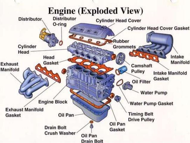
COMPONENTS OF IC ENGINE
1. Cylinder block
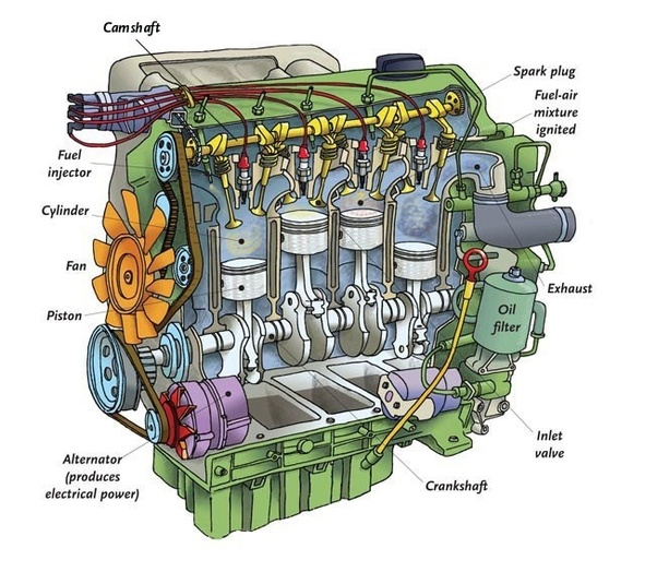
Cylinder is the main body of IC engine. Cylinder is a part in which the intake of fuel, compression of fuel and burning of fuel take place. The main function of cylinder is to guide the piston. It is in direct contact with the products of combustion so it must be cooled. For cooling of cylinder, a water jacket (for liquid cooling used in most of cars) or fin (for air cooling used in most of bikes) are situated at the outer side of cylinder. At the upper end of cylinder, cylinder head and at the bottom end crank case is bolted. The upper side of cylinder is consisting a combustion chamber where fuel burns. To handle all this pressure and temperature generated by combustion of fuel, cylinder material should have high compressive strength. So it is made by high grade cast iron. It is made by casting and usually cast in one piece.
2. Cylinder head
The top end of the engine cylinder is closed by means of removable cylinder head. There are two holes or ports at the cylinder head, one for intake of fuel and other for exhaust. Both the intake and exhaust ports are closed by the two valves known as inlet and exhaust valve. The inlet valve, exhaust valve, spark plug, injector etc. are bolted on the cylinder head. The main function of cylinder head is to seal the cylinder block and not to permit entry and exit of gases on cover head valve engine. Cylinder head is usually made by cast iron or aluminum. It is made by casting or forging and usually in one piece.
3. Piston
A piston is fitted to each cylinder as a face to receive gas pressure and transmit the thrust to the connecting rod. It is a prime mover in the engine. The main function of piston is to give tight seal to the cylinder through bore and slide freely inside the cylinder. Piston should be light and sufficient strong to handle gas pressure generated by combustion of fuel. So the piston is made by aluminum alloy and sometimes it is made by cast iron because light alloy piston expands more than cast iron so they need more clearances to the bore.
4. Piston rings
A piston must be a fairly loose fit in the cylinder so it can move freely inside the cylinder. If the piston is too tight fit, it would expand as it got hot and might stick tight in the cylinder and if it is too loose it would leaks the vapor pressure. To provide a good sealing fit and less friction resistance between the piston and cylinder, pistons are equipped with piston rings. These rings are fitted in grooves which have been cut in the piston. They are split at one end so they can expand or slipped over the end of piston. A small two stroke engine has two piston rings to provide good sealing but a four-stroke engine has an extra ring which is known as oil ring. Piston rings are made of cast iron of fine grain and high elastic material which is not affected by the working heat. Sometimes it is made by alloy spring steel.
5. Connecting rod
Connecting rod connects the piston to crankshaft and transmits the motion and thrust of piston to crankshaft. It converts the reciprocating motion of the piston into rotary motion of crankshaft. There are two end of connecting rod; one is known as big end and other as small end. Big end is connected to the crankshaft and the small end is connected to the piston by use of piston pin. The connecting rods are made of nickel, chrome, and chrome vanadium steels. For small engines the material may be aluminum.
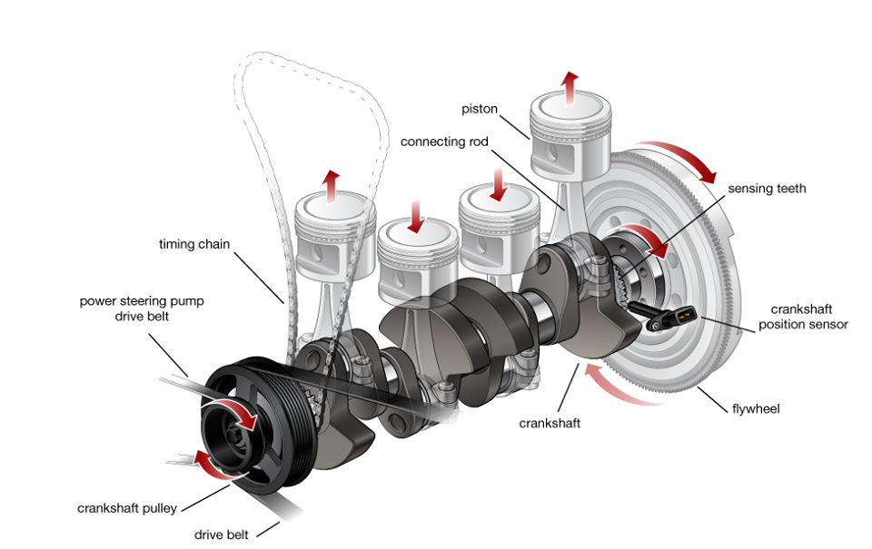
6. Crankshaft
The crankshaft of an internal combustion engine receives the efforts or thrust supplied by piston to the connecting rod and converts the reciprocating motion of piston into rotary motion of crankshaft. The crankshaft mounts in bearing so it can rotate freely. The shape and size of crankshaft depends on the number and arrangement of cylinders. It is usually made by steel forging, but some makers use special types of cast-iron such as spheroidal graphitic or nickel alloy castings which are cheaper to produce and have good service life.
7. Engine bearing
Everywhere there is rotary action in the engine, bearings are needed. Bearings are used to support the moving parts. The crankshaft is supported by bearing. The connecting rod big end is attached to the crank pin on the crank of the crankshaft by a bearing. A piston pin at the small end is used to attach the rod to the piston is also rides in bearings. The main function of bearings is to reduce friction between these moving parts. In an IC engine sliding and rolling types of bearing used. The sliding type bearing which are sometime called bush is use to attach the connecting rod to the piston and crankshaft. They are split in order to permit their assembly into the engine. The rolling and ball bearing is used to support crankshaft so it can rotate freely. The typical bearing half is made of steel or bronze back to which a lining of relatively soft bearing material is applied.
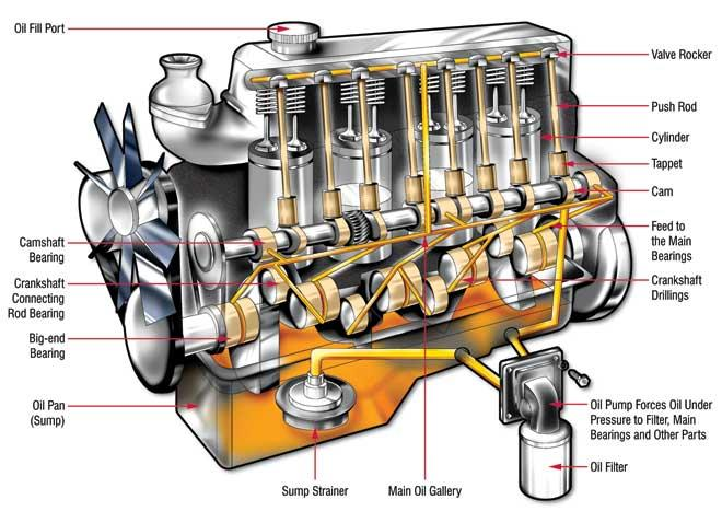
8. Crankcase
The main body of the engine at which the cylinder are attached and which contains the crankshaft and crankshaft bearing is called crankcase. It serves as the lubricating system too and sometime it is called oil sump. All the oil for lubrication is placed in it.
9. Valves
To control the inlet and exhaust of internal combustion engine, valves are used. The number of valves in an engine depends on the number of cylinders. Two valves are used for each cylinder one for inlet of air-fuel mixture inside the cylinder and other for exhaust of combustion gases. The valves are fitted in the port at the cylinder head by use of strong spring. This spring keep them closed. Both valves usually open inwards.
10. Spark plug
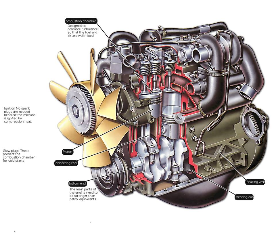
It is used in spark ignition engine. The main function of a spark plug is to conduct a high potential from the ignition system into the combustion chamber to ignite the compressed air fuel mixture. It is fitted on cylinder head. The spark plug consists of a metal shell having two electrodes which are insulated from each other with an air gap. When high potential current supply to spark plug it jumping from the supply electrode and produces the necessary spark.
11. Injector
Injector is usually used in compression ignition engine. It sprays the fuel into combustion chamber at the end of compression stroke. It is fitted on cylinder head.
12. Manifold
The main function of manifold is to supply the air fuel mixture and collects the exhaust gases equally from all cylinder. In an internal combustion engine two manifold are used, one for intake and other for exhaust. They are usually made by aluminum alloy.
13. Camshaft
Camshaft is used in IC engine to control the opening and closing of valves at proper timing. For proper engine output inlet valve should open at the end of exhaust stroke and closed at the end of intake stroke. So to regulate its timing, a cam is use which is oval in shape and it exerts a pressure on the valve to open and release to close. It is drive by the timing belt which drives by crankshaft. It is placed at the top or at the bottom of cylinder.
14. Gudgeon pin or piston pin
These are hardened steel parallel spindles fitted through the piston bosses and the small end bushes or eyes to allow the connecting rods to swivel. It connects the piston to connecting rod. It is made hollow for lightness.
15. Pushrod
Pushrod is used when the camshaft is situated at the bottom end of cylinder. It carries the camshaft motion to the valves which are situated at the cylinder head.
16. Flywheel
A flywheel is secured on the crankshaft. The main function of flywheel is to rotate the shaft during preparatory stroke. It also makes crankshaft rotation more uniform.
TYPES OF I.C ENGINE
I.C. engine is widely used in automobile industries so it is also known as automobile engine. An automobile engine may be classified in many manners.

According to number of stroke:
1. Two stroke engine
In a two stroke engine a piston moves one time up and down inside the cylinder and complete one crankshaft revolution during single time of fuel injection. This type of engine has high torque compare to four stroke engine. These are generally used in scooters, pumping sets etc.
2. Four stroke engine
In a four stroke engine piston moves two times up and down inside the cylinder and complete two crankshaft revolutions during single time of fuel burn. This type of engines has high average compare to two stroke engine. These are generally used in bikes, cars, truck etc.
According to design of engine:
1. Reciprocating engine (piston engine)
In reciprocating engine the pressure force generate by combustion of fuel exerted on a piston (A device which free to move in reciprocation inside the cylinder). The piston starts reciprocating motion (too and fro motion). This reciprocating motion converts into rotary motion by use of crank shaft. So the crank shaft starts to rotate and make rotate the wheels of the vehicle. These are generally used in all automobile.
2. Rotary engine (Wankel engine)
In rotary engine there is a rotor which frees to rotate. The pressure force generated by burning of fuel is exerted on this rotor so the rotor rotate and starts to rotate the wheels of vehicle. This engine is developed by Wankel in 1957. This engine is not used in automobile in present days.
According to fuel used:

1. Diesel engine
These engines use diesel as the fuel. These are used in trucks, buses, cars etc.
2. Petrol engine
These engines use petrol as the fuel. These are used in bikes, sport cars, luxury cars etc.
3. Gas engine
These engines use CNG and LPG as the fuel. These are used in some light motor vehicles.
According to method of ignition:
1. Compression ignition engine
In these types of engines, there is no extra equipment to ignite the fuel. In these engines burning of fuel starts due to temperature rise during compression of air. So it is known as compression ignition engine.
2. Spark ignition engine
In these types of engines, ignition of fuel start by a spark, generated inside the cylinder by some extra equipment (Spark Plug). So it is known as spark ignition engine.
According to number of cylinder:
1. Single cylinder engine
In this type of engines have only one cylinder and one piston connected to the crank shaft.
2. Multi-cylinder engine
In this type of engines have more than one cylinder and piston connected to the crank shaft
According to arrangement of cylinder:
1. In-line engine
In this type of engines, cylinders are positioned in a straight line one behind the other along the length of the crankshaft.
2. V-type engine
An engine with two cylinder banks inclined at an angle to each other and with one crankshaft known as V-type engine.
3. Opposed cylinder engine
An engine with two cylinders banks opposite to each other on a single crankshaft (V-type engine with 180o angle between banks).
4. W-type engine
An engine same as V-type engine except with three banks of cylinders on the same crankshaft known as W-type engine.
5. Opposite piston engine
In this type of engine there are two pistons in each cylinder with the combustion chamber in the center between the pistons. In this engine, a single combustion process causes two power strokes, at the same time.
6. Radial engine
It is an engine with pistons positioned in circular plane around the central crankshaft. The connecting rods of pistons are connected to a master rod which, in turn, connected to the crankshaft.
According to air intake process:
1. Naturally aspirated
In this types of engine intake of air into cylinder occur by the atmospheric pressure.
2. Supercharged engine
In this type of engine air intake pressure is increased by the compressor driven by the engine crankshaft.
3. Turbocharged engine
In this type of engine intake air pressure is increase by use of a turbine compressor driven by the exhaust gases of burning fuel.
ENGINE TERMINOLOGY
1. Top dead center (T.D.C.)
In a reciprocating engine the piston moves to and fro motion in the cylinder. When the piston moves upper direction in the cylinder, a point at which the piston comes to rest or change its direction known as top dead center. It is situated at top end of cylinder.
2. Bottom dead center (B.D.C.)
When the piston moves in downward direction, a point at which the piston come to rest or change its direction known as bottom dead center. It is situated in bottom side of cylinder.
3. Stroke (L)
The maximum distance travel by the piston in single direction is known as stroke. It is the distance between top dead center and bottom dead center.
4. Bore (b)
The inner diameter of cylinder known as bore of cylinder.
5. Maximum or total volume of cylinder (Vtotal)
It is the volume of cylinder when the piston is at bottom dead center. Generally, it is measure in centimeter cube (c.c.).
6. Minimum or clearance volume of cylinder (Vclearance)
It is the volume of cylinder when the piston is at top dead center.
7. Swept or displace volume (Vswept)
It is the volume which swept by the piston. The difference between total volume and clearance volume is known as swept volume.
Swept volume = Total volume – Clearance volume
8. Compression ratio
The ratio of maximum volume to minimum volume of cylinder is known as the compression ratio. It is 8 to 12 for spark ignition engine and 12 to 24 for compression ignition engine.
Compression ratio = Total volume / Clearance volume
9. Ignition delay
It is the time interval between the ignition start (spark plug start in S.I. engine and inject fuel in C.I. engine) and the actual combustion starts.
10. Stroke bore ratio
Stroke bore ratio is the ratio of bore (diameter of cylinder) to length of stroke. It is generally equal to one for small engine and less than one for large engine.
Stroke bore ratio = inner diameter of cylinder / length of stroke
11. Mean effective pressure
The average pressure acting upon the piston is known as mean effective pressure. It is given by the ratio of the work done by the engine to the total volume of engine.
Mean effective pressure = Work done by engine / Total volume of cylinder