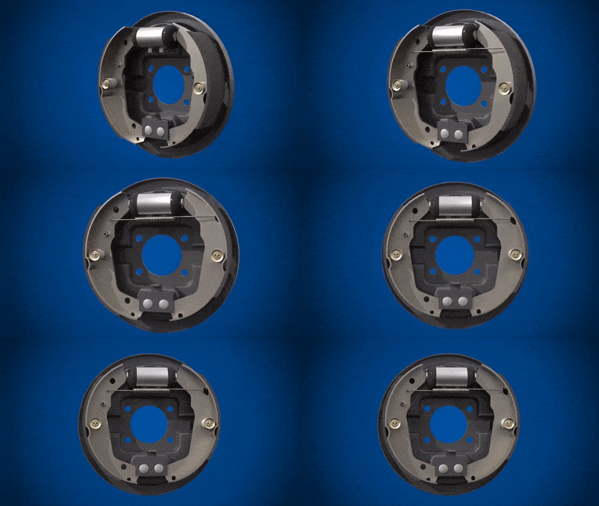
Cómo funciona el sistema de frenos de tambor en el auto?

DRUM BRAKE: FUNCTION, COMPONENTS, WORKING PRINCIPLE AND TYPES

A drum brake is a brake that uses friction caused by a set of shoes or pads that press outward against a rotating cylinder-shaped part called a brake drum.

The term drum brake usually means a braking system in which shoes press on the inner surface of the drum. When shoes press on the outside of the drum, it is usually called a clasp brake. Where the drum is pinched between two shoes, similar to a conventional disc brake, it is sometimes called a pinch drum brake, though such brakes are relatively rare. A related type called a band brake uses a flexible belt or «band» wrapping around the outside of a drum.

Drum brakes are primarily used at the rear axle of small and compact class vehicles.

FUNCTION

Drum brakes have been around for almost as long as the automobile itself and are still fitted today in a modified and more sophisticated form in modern cars. The term drum brake describes the design principle: namely, an enclosed cylindrical structure.

DRUM BRAKE COMPONENTS

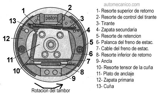
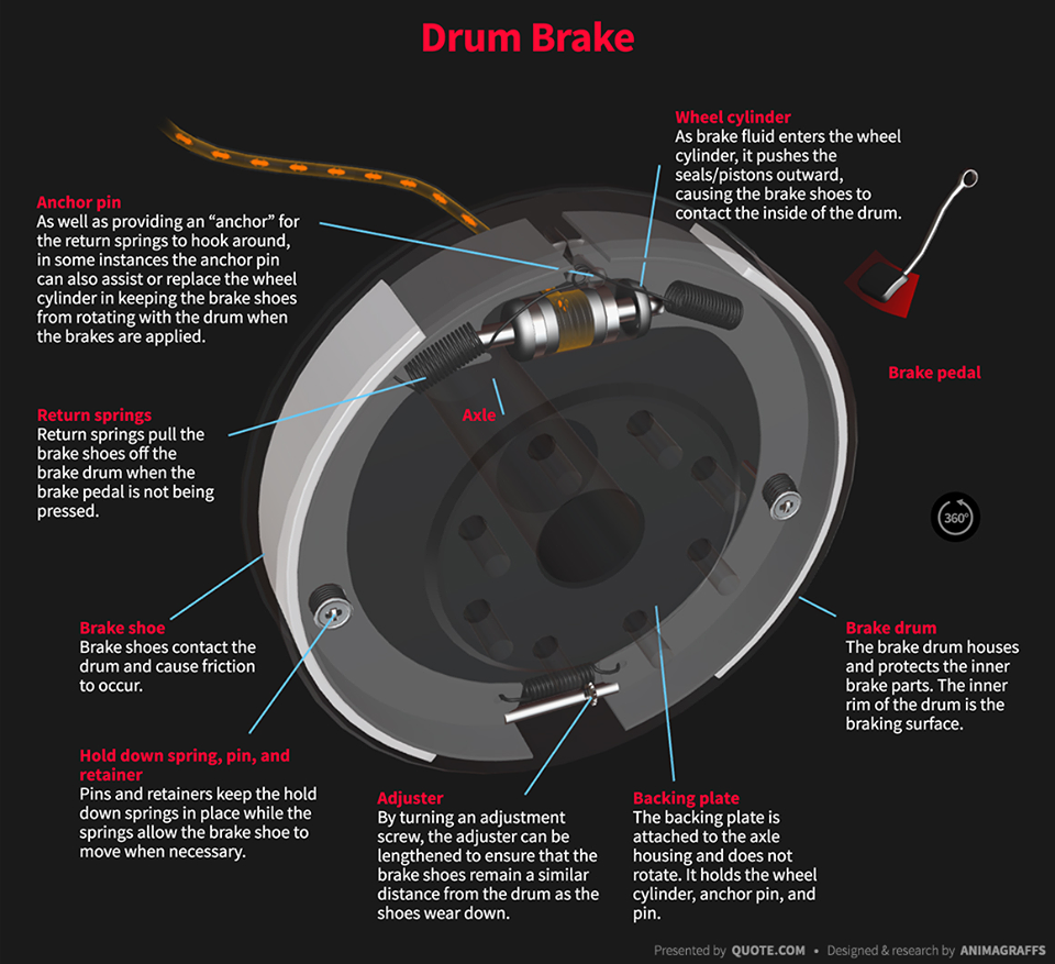
A drum brake comprises the following components:

1. Backing plate:
Provides a solid base for other components in the drum brake attached to the axle sleeve.

2. Brake drum:
Bolted to the wheel hub and spins with the wheel. Often made of cast iron, and is resistant to heat and wear. This is what you see when you look at an assembled drum brake and is the component upon which braking force is applied to slow or stop the car.

3. Wheel cylinder:
Contains two pistons, one at each end of the cylinder, to operate the brake shoes. The cylinder applies pressure to the pistons, which pushes the brake shoes towards the drum, slowing or stopping the car. One cylinder is needed per wheel.

4. Brake shoe:
Pushes into the drum to create the friction necessary to slow or stop the car. Secured to the backing, but able to slide when pressure from the wheel cylinder is applied. It has a lining attached to it, made up of organic or metallic compounds. The lining is what actually comes in contact with the drum and wears away with use. Each brake contains two shoes. The primary shoe is closer to the front of the vehicle, while the secondary shoe is closer to the rear. Depending on the type and brand, the brake shoes may be interchangeable.

5. Automatic adjuster:
Keeps the brake shoes at a consistent distance away from the drum, even as the lining wears away.

6. Return springs:
Pulls the brake shoes back away from the drum when the driver lets off the brake pedal.

The brake drum is fixed to the wheel and turns with it. On braking, the wheel cylinder forces the fixed brake shoes apart and presses them against the brake drum, thus slowing it down. When the brake is released, the return springs move the brake shoes back to their original position.

WORKING PRINCIPLE

When the driver steps on the brake pedal, the power is amplified by the brake booster (servo system) and changed into hydraulic pressure (oil-pressure) by the master cylinder. The pressure reaches the brakes on the wheels via tubing filled with brake oil (brake fluid). The delivered pressure pushes the pistons on the brakes of the four wheels. The pistons press the brake linings, which are friction materials, against the inside surfaces of the brake drums which rotate with the wheels. The linings are pressed on the rotating drums, which in turn decelerate the wheels, thereby slowing down and stopping the vehicle.

TYPES OF DRUM BRAKES

There are mainly three types – mechanical, hydraulic & pneumatic assisted Drum Brakes.

1. Mechanical:

In the mechanical Drum brake system such as in two-wheeler & auto-rickshaw, the brake shoes are actuated by a cam, which is attached to the brake linkage & pedal. When you press the brake pedal, the cam turns. Thus, it causes the brake shoes to expand outwards and rub against the drum.
The friction between the brake linings and the drum causes the drum to stop rotating, thereby the wheel to stop. When you release the brake pedal, the retracting springs bring the brake shoes back to their original position. This results in a gap between them and the drum and to again spin it freely.

2. Hydraulic:

The hydraulic Drum brake system such as in cars is a bit superior to a mechanical one. In this design, the hydraulic wheel cylinder replaces the cam. In the hydraulic system, instead of a cam, the wheel cylinder’s pistons push the brake shoes outward. The brake shoes fit on the anchor plate or braking plate. It holds the brakes system parts together and on to the car’s axle. When you press the brake pedal, the oil in the brake master cylinder multiplies the hydraulic force sent to the wheel cylinders. Thus, it causes its pistons to push outwards. The pistons, in turn, cause the brake shoes to expand and rub against the drum. The friction between the brake linings and the drum causes the drum to stop rotating, thereby the wheel to stop.

3. Pneumatic assisted:

The third type – pneumatic assisted Drum-brake system; actuated by air-pressure, which works on the same principle of that of the mechanical Drum brake system. It is also operated by a bigger size cam or the ‘S’ shaped cam and is popularly known as the “S-Cam” brake system. However, high-pressure compressed air actuates a pneumatic piston which turns the cam. Mostly the medium to heavy commercial vehicles use this type of drum brake system.

BASED ON PRINCIPLE

1. Leading/trailing shoe type drum brake

«Leading (or primary) shoe» is a term referring to the shoe that moves in the direction of rotation when it is being pressed against the drum. The other shoe is called the “trailing (secondary) shoe.” The leading shoe is pressed in the same direction as the rotation of the drums, and this rotation helps to press the shoes against the drum with greater pressure for stronger braking force. This is called the servo effect (self-boosting effect) which realizes the powerful braking forces of drum brakes.

Structurally, it has a wheel cylinder housing a piston with which hydraulic pressure is generated to push the two shoes against the drum’s inner surface.

The two shoe function in a way they both become either the trailing shoe or leading shoe depending on whether the vehicle is traveling forward or backward. Drum brakes generate consistent braking force whether the vehicle travels forward or backward. This is because drum brakes generate the same braking force in either direction. Generally, this type is used for the rear brakes of passenger cars.

2. Twin leading shoe type drum brake

This type of drum brake has two-wheel cylinders and two leading shoes. Each wheel cylinder presses on one shoe so that both shoes act as leading ones when the vehicle moves forward, providing superior braking force.
Each of the pistons housed in the wheel cylinders displaces in one direction, so when the vehicle is in reverse both shoes act as trailing ones. This type is used mainly for the front brakes of small-to-mid-sized trucks.
The dual twin leading shoe type has pistons that displace in both directions, making it possible for both shoes to act as leading ones, regardless of the direction of travel. This type is mainly used for the rear brakes of small-to-mid-sized trucks.

3. Duo-servo type drum brake

The duo-servo type features a structure where two brake shoes, called the primary shoe and secondary shoe, are linked via an adjuster. Strong pressure from the servo effect (self-boosting effect) of the primary shoe is transmitted to the linked secondary shoe, thus generated a very large braking force.
This type is mainly used for parking brakes on passenger cars, the center brakes on trucks, and brakes on forklifts.

ADVANTAGES AND DISADVANTAGES

Advantages of Drum brake system:

1. Simple design and parts
2. Easy & cheaper to manufacture
3. Low maintenance cost
4. Comparatively longer life

Disadvantages of Drum Brake system:

1. Low braking force compared to Discs
2. Brakes ‘fade’ when applied for a prolonged time
3. The brake shoe lining made of asbestos is harmful to humans
4. When wet, the braking grip reduces considerably
5. Non-asbestos linings catch moisture, causing Drum brakes to grab suddenly

SAFETY

The brake drum is one of the most important vehicle systems when it comes to safety. It is relatively low-wear and has a long service life. A specialist workshop should be consulted immediately if the deterioration in the braking action of a drum brake becomes noticeable. Drum brakes are only to be replaced by qualified personnel. The manufacturer’s installation instructions must be observed when doing so.

Qué son los troqueles y el troquelado? Y como funciona en la industria automotriz?

El troquelado o estampado es proceso en el cual sin formar viruta, se somete mecánicamente una lámina a ciertas transformaciones con el objetivo de obtener una pieza de forma geométrica propia.

Este trabajo del troquel no lo realiza el mismo ya que necesita de un dispositivo de prensas mecánicas o hidráulicas(generalmente de movimiento rectilíneo alternativo) que se encargan de ejercer la fuerza para poder realizar la embutidera, corte o punzonado

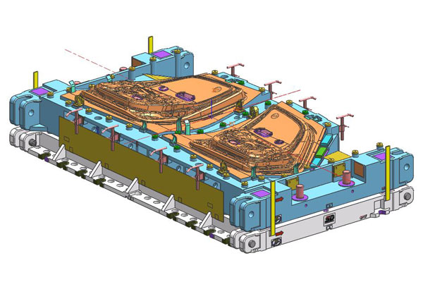
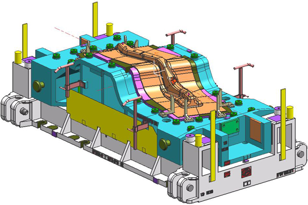
Los principales componentes que se someten a este tipo de mecanizados es lo que en diseño mecánico conocemos como chapa metálica (sheet metal) que son laminas de material metálico, el cual mediante troqueles progresivos y prensas se generan la mayoría de los perfiles de las carrocerías automotrices, si bien sabemos los troqueles automotrices no son nada pequeños ya que por las dimensiones y por el número de operaciones que hace por troquel, podemos hacer diferentes piezas en una sola caída de prensa, y mediante un corte/punzonado y/o embutido puede hacer dicha operación

Existen tres tipos de troquelos

Simples: en este tipo de troqueles solo se realiza una operaciones para hacer piezas simples y muchas veces se requieren de mas troqueles para hacer mas piezas

Compuestos: Se caracteriza por poseer varios punzones que requiere uno de otro de manera que un punzón es matriz respecto a otros punzones se utilizan principalmente para piezas con agujeros que deben estar centrados con gran precisión

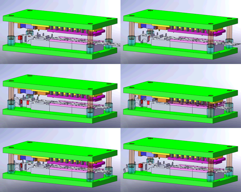
Progresivos: Este tipo de troquel es más sofisticado ya que en el se pueden realizar varias operaciones de corte y formado sobre la lamina de metal conformando distintas fases del proceso. Los punzones están en linea y en ellos va la secuencia de operación empezando desde el corte hasta el pre acabado final de la pieza

Las partes principales de los troqueles están definidos en las siguientes imágenes en diferentes disposiciones de troqueles

Bien como lo haz notado realizar un proceso de troquelado es un proceso complejo y de mucha precisión ya que tanto el calculo del tonelaje de golpe para el corte de la pieza es un reto así como el diseño del mismo troquel en plataformas CAD es un reto, y así como calcular los centros y la simulación que tendrá el corte deseado para alcanzar a tener la medida especifica para la operación del producto, en los próximos capítulos iremos viendo más a cerca de este artefacto de manufactura tan importante en la industria automotriz

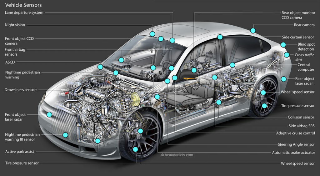
Cuáles son los sensores que se encuentran instalados en el vehículo?

VEHICLE SENSORS: FUNCTIONS AND TYPES

In a way, sensors are the sensory organs of the vehicle. A fundamental component of electronic control systems, they must record physical or chemical variables and convert them into electrical signals…

Function

In a way, sensors are the sensory organs of the vehicle. A fundamental component of electronic control systems, they must record physical or chemical variables and convert them into electrical signals.

TYPES OF SENSORS

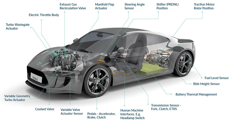
In recent years, there has been an explosion in the number of different types of sensor. Many new types of sensor have been seen in particular in the area of safety and convenience electronics. Essentially, sensors can be categorised as follows:

1. Position sensors (distance/angle sensors)

Position sensors are used to capture the position of

* the throttle valve,
* of the accelerator or brake pedal,
* of the distance and angular positions in diesel injection pumps,
* of the fill level in the fuel tank,
* of the steering angle,
* of the angle of tilt, etc.

The ultrasonic and radar sensors used to determine distances from obstacles for modern driver assist systems also belong in this category.

2. Speed and velocity sensors

Speed and velocity sensors are used to determine

* the speed of crankshafts,
* camshafts and
* diesel injection pumps or
* wheel speeds.

Yaw rate sensors also belong in this category. They detect the rotational movement of the vehicle about its own axis and are needed for ESP.

3. Acceleration sensors

Acceleration sensors record the acceleration of the car body and are used in passive safety systems (airbags, seat belt tensioners, roll bars) and driving stability systems such as ABS and ESP, as well as in chassis control.

4. Pressure sensors

Pressure sensors are used to capture a wide variety of pressures including

* suction or charging pressure,
* fuel pressure, brake pressure,
* tyre pressure,
* hydraulic reservoir pressure (for ABS and power steering),
* refrigerant pressure (air conditioning system),
* modulation pressure (automatic transmission) and so on.

5. Temperature sensors

Temperature sensors are used to capture temperatures, e.g. in the context of measuring

* suction or charge air temperature,
* ambient and interior temperatures,
* evaporator temperature (air conditioning system),
* coolant temperature,
* engine oil temperature,
* tyre air temperature and so on.

6. Force and torque sensors

Force and torque sensors are used to measure forces such as

* pedal force,
* drive,
* brake and steering torque forces or
* the weight of the occupants of a vehicle (for adaptive restraint systems).

7. Flow-meters

Flow-meters are used to capture the fuel requirement and the amount of air drawn in by the engine.

8. Gas sensors

Gas sensors capture the composition of the exhaust gas (oxygen sensor, NOx sensor) or detect hazardous substances in the fresh air supply.

EXAMPLES OF SENSORS FOR ENGINE CONTROL:

* Pulse sensor, crankshaft

The crankshaft sensor captures the engine speed and the position of the crankshaft. The control unit uses these values to calculate the injection pulse and the ignition pulse.

* Camshaft position

The camshaft sensor is located at the cylinder head and scans a ring gear at the camshaft. This information is used, for example, for the start of injection, for the signal to activate the solenoid valve for the pump/nozzle injection system and for cylinder-specific knock control.

* Air mass meter

The air mass meter is installed between the air filter housing and the intake manifold. It measures the air mass drawn in by the engine. This variable provides the basis for calculating the fuel quantity that must be supplied to the engine.

* Intake air temperature/Outside temperature/Interior temperature

Air temperature sensors capture the temperature of the ambient air. The values measured are used to control various systems (e.g. the air conditioning system) or as correction values for the injection system. The installation location is determined by the air temperature to be measured. The sensor for the intake air temperature, for example, is located in the air duct for the intake air.

* Coolant temperature

The coolant temperature sensor is screw-mounted in the cooling system. The gauge tip protrudes into the coolant and records its temperature. The control unit uses this value to adapt the amount of fuel injected to the engine temperature.

* Throttle position

Throttle valve sensors are attached to the throttle valve axle. They monitor the opening angle of the throttle valve. From the values, the engine electronics calculates the fuel quantity which is injected based on other factors.

* Knock sensors

Knocking is an uncontrolled form of combustion in a petrol engine. As continuous knocking can damage the engine, it must be checked and regulated. The engine control unit evaluates the voltage signals received from the knock sensor and regulates the ignition point in a range just below what is known as the knock limit. Knock sensors are permanently monitored by the control unit.

* Intake pipe pressure

The intake pipe pressure sensor measures the intake pipe vacuum downstream of the throttle valve and forwards this value to the engine control unit as an electrical signal. This is combined with the value of the air temperature sensor so that the air mass drawn in can be calculated.

* Oxygen sensors

The oxygen sensor measures the residual oxygen content in the exhaust gas in order to ensure an optimum combustion mixture at all times. Depending on the type of sensor, a chemical element (titanium dioxide/zirconium dioxide) and the residual oxygen content of the exhaust gas bias a voltage, which is then used by the control unit as a measured variable.

EXAMPLES OF SENSORS FROM CAR BODY ELECTRONICS:

* Wheel speed

The wheel speed is used by driving safety systems such as ABS and ASR as a speed value as well as by GPS systems to calculate distance travelled. A fault will cause these systems to fail, significantly impairing safety.

* Speed, transmission

The transmission sensor captures the transmission speed. The speed signal is used by the control unit for precision control of the shift pressure during shifting and to decide which gear should be engaged when.

* Speed, distances travelled

Distance sensors are used to capture driving speed. They are mounted on the transmission or rear axle. They information obtained is required for the speedometer, cruise control and converter slip control.

* Engine oil level/Coolant level

For reasons of operational safety and for increased comfort, levels such as engine oil, coolant and washer fluid are monitored with level sensors. The level sensors send a signal to the engine control unit which activates an indicator lamp.

* Brake lining wear

The brake wear sensors are located on the brake linings and are subject to the same wear. A visual signal tells the driver that the wear limit has been reached.

* Safety

The sensor information provides the basis for the function of numerous active and passive safety systems. Thanks to significant progress in the development of new sensors, there has been a constant increase in the capabilities of safety and driver assist systems in recent years. Sensors thus have a key role to play in increasing safety on our roads.

Some of safety systems are

1. Forward collision avoidance system –

It alerts the driver when the vehicle is getting close to another vehicle in front of it. It employs various sensors such as cameras, RADAR or LIDAR to sense the objects or other vehicles in front of the vehicle. A forward collision warning system provided with autonomous braking can reduce the speed of the vehicle thereby mitigating the effect of collision.

2. Adaptive cruise control –

Adaptive cruise control maintains the vehicle’s pre-set speed. It automatically slows down the vehicle in heavy traffic to maintain a safe gap. Forward-mounted sensors keep track of the distance to the vehicle at the front. The vehicle accelerates to maintain the preset cruise speed as the traffic speeds up.

3. Lane departure warning and prevention system –

This system employs cameras to track the position of the vehicle within the lane and alert the driver if the vehicle is in danger. Certain systems offer haptic warnings such as seat or steering vibrations, while others provide audible and/or visual warnings.

4. Blind spot detection system –

This sensor network system monitors the blind spots at the front, side and rear areas of the vehicle. Most of the systems provide visual alerts appearing on or near the side view mirrors upon detecting the blind spot.

An audible alert is activated when the driver signals a turn, and the vehicle is headed towards the blind spot on the turning side.

Certain systems may also activate the steering controls or brake to maintain the vehicle in its lane.

5. Park assist and backover prevention system –

assists drivers to park and back up their vehicles. Rear object detection systems make use of sensors and cameras to enable the driver to look for the objects in the rear side of the vehicle while backing up.

6. Adaptive headlight

it alert drivers to visualize objects better on dark, curved roads. The headlight pivots in the direction of a moving vehicle to illuminate the road ahead based on the vehicle’s speed and steering wheel movement.

7. Fatigue warning systems

it employ sophisticated algorithms to monitor the steering control and other behaviors such as blink duration and blink rate of the driver. This system is designed to warn the driver if it detects drowsiness or inattention.

8. Curve speed warning system

it monitors the vehicle as it approaches bends in the road by using a global positioning system and digital map. Curve speed sensors alerts the driver if the system senses that the vehicle is nearing a curve at an over speed.

* Environmental protection

Sensors make modern vehicles not only safer but also cleaner. They supply the basic information for clean and effective fuel combustion in the engine, thereby enabling exhaust emissions values and fuel consumption to be reduced significantly. Finally, they support the reliable functioning of high-efficiency exhaust re-treatment systems. Examples include the controlled 3-way catalytic converter, the diesel particulate filter or the DeNOx catalytic converter.

Copyright © All rights reserved. | StoreCommerce by AF themes.
YouTube
YouTube
Instagram