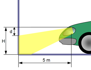
El principal objetivo de las luces es algo obvio en un principio ya que cuando cae la noche la visibilidad se limita y es por ello que debemos emplear los dispositivos de iluminación para iluminar el camino y así mantener una conducción segura . También podemos utilizarlos como señales de aviso a otros conductores acerca de la presencia del vehículo, posición, tamaño, dirección de desplazamiento y las intenciones del conductor.
Tipos de luces automotrices
luces de posición
de cruce
de largo alcance
intermitentes
luces antiniebla
luces de freno
luces de emergencia
Un foco se puede considerar como una pieza de recambio con una vida útil limitada. Sin embargo, el foco es parte del sistema de iluminación. Es un componente activo de una unidad donde todos los elementos deben ser perfectamente ajustados entre sí.
HEVs are vehicles propelled by more than one power source such as an engine and electric motor. They are classified by type and level. The advantages of HEVs are improved fuel economy, efficiency, and reduced emissions. The disadvantage of HEVs is cost. The cost aspect may be offset in years to come due to higher gas prices and improved HEV technologies. For more information on types and levels of HEVs, visit their respective pages in the menu on the left.
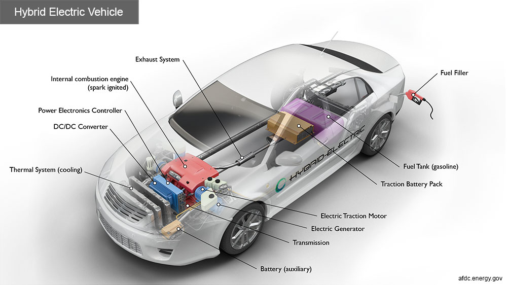
Hybrid electric vehicles are powered by an internal combustion engine and an electric motor, which uses energy stored in batteries. A hybrid electric vehicle cannot be plugged in to charge the battery. Instead, the battery is charged through regenerative braking and by the internal combustion engine. The extra power provided by the electric motor can potentially allow for a smaller engine. The battery can also power auxiliary loads like sound systems and headlights, and reduce engine idling when stopped. Together, these features result in better fuel economy without sacrificing performance.
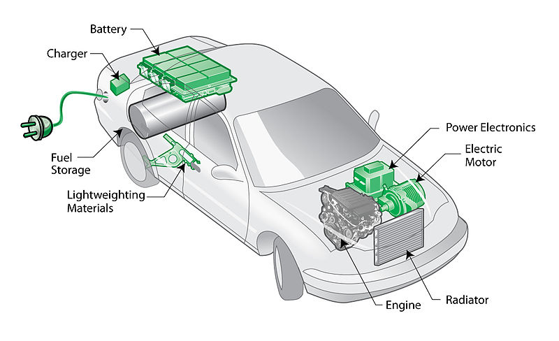
COMPONENTS OF A HYBRID ELECTRIC CAR
Battery (auxiliary): In an electric drive vehicle, the auxiliary battery provides electricity to start the car before the traction battery is engaged and also powers vehicle accessories.
DC/DC converter: This device converts higher-voltage DC power from the traction battery pack to the lower-voltage DC power needed to run vehicle accessories and recharge the auxiliary battery.
Electric generator: It generates electricity from the rotating wheels while braking, transferring that energy back to the traction battery pack. Some vehicles use motor generators that perform both the drive and regeneration functions.
Electric traction motor: Using power from the traction battery pack, this motor drives the vehicle’s wheels. Some vehicles use motor generators that perform both the drive and regeneration functions.
Exhaust system: The exhaust system channels the exhaust gases from the engine out through the tailpipe.
Fuel filler: This is a filler or «nozzle» used to add fuel to the tank.
Fuel tank (gasoline): This tank stores gasoline on board the vehicle until it’s needed by the engine.
Internal combustion engine (spark-ignited): In this configuration, fuel is injected into either the intake manifold or the combustion chamber, where it is combined with air, and the air/fuel mix is ignited by the spark from a spark plug.
Power electronics controller: This unit manages the flow of electrical energy delivered by the traction battery, controlling the speed of the electric traction motor and the torque it produces.
Thermal system (cooling): This system maintains a proper operating temperature range of the engine, electric motor, power electronics, and other components.
Traction battery pack: Stores electricity for use by the electric traction motor.
Transmission: The transmission transfers mechanical power from the engine and/or electric traction motor to drive the wheels.
FUEL-EFFICIENT SYSTEM DESIGN
HEVs can be either mild or full hybrids, and full hybrids can be designed in series or parallel configurations.
• Mild hybrids—also called micro hybrids—use a battery and electric motor to help power the vehicle and can allow the engine to shut off when the vehicle stops (such as at traffic lights or in stop-and-go traffic), further improving fuel economy. Mild hybrid systems cannot power the vehicle using electricity alone. These vehicles generally cost less than full hybrids but provide less fuel economy benefits than full hybrids.
• Full hybrids have larger batteries and more powerful electric motors, which can power the vehicle for short distances and at low speeds. These vehicles cost more than mild hybrids but provide better fuel economy benefits.
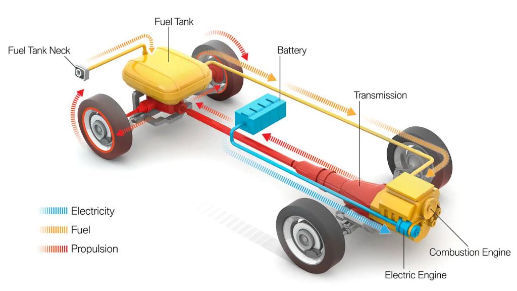
ENERGY FLOW DIAGRAMS AND DESCRIPTIONS
1. Series (Extended-Range) Hybrid
A series hybrid is like a battery electric vehicle (BEV) in design. Here, the combustion engine drives an electric generator instead of directly driving the wheels. The generator both charges a battery and powers an electric motor that moves the vehicle. When large amounts of power are required, the motor draws electricity from both the battery and the generator. Series hybrids may also be referred to as extended-range electric vehicles (EREVs) or range-extended electric vehicles (REEVs) since the gas engine only generates electricity to be used by the electric motor and never directly drives the wheels. Modern examples include the Cadillac ELR, Chevrolet Volt, and Fisker Karma.
2. Parallel Hybrid
A parallel hybrid is propelled by both an internal combustion engine (ICE) and an electric motor connected to a mechanical transmission. Power distribution between the engine and the motor is varied so both run in their optimum operating region as much as possible. There is no separate generator in a parallel hybrid. Whenever the generator’s operation is needed, the motor functions as a generator. In a parallel mild hybrid, the vehicle can never drive in pure electric mode. The electric motor turns on only when a boost is needed.
3. Series-Parallel Hybrid
The vehicle can be powered by the gasoline engine working alone, the electric motor by itself, or by both energy converters working together. Power distribution between the engine and motor is designed so that the engine can run in its optimum operating range as much as possible.
Most hybrids use several advanced technologies:
Regenerative Braking. Regenerative braking recaptures energy normally lost during coasting or braking. It uses the forward motion of the wheels to turn the motor. This generates electricity and helps slow the vehicle.
Electric Motor Drive/Assist. The electric motor provides power to assist the engine in accelerating, passing, or hill climbing. This allows a smaller, more-efficient engine to be used. In some hybrids, the electric motor alone propels the vehicle at low speeds, where gasoline engines are least efficient.
Automatic Start/Stop. Automatically shuts off the engine when the vehicle comes to a stop and restarts it when the accelerator is pressed. This reduces wasted energy from idling.
ADVANTAGES & DISADVANTAGES OF HYBRID CARS
ADVANTAGES OF HYBRID CARS
Switching to a hybrid car has many advantages, a few of which we have highlighted below: 1. Environmentally Friendly 2. Economical 3. Less Fossil Fuel Dependent 4. Regenerative Braking System 5. Light Build 6. Higher Resale Value
DISADVANTAGES OF A HYBRID CAR
1. Less Power 2. Expensive to Purchase 3. Poorer Handling 4. High Maintenance Cost 5. High Voltage Batteries
ELECTRIC VEHICLES: COMPONENTS AND WORKING PRINCIPLE
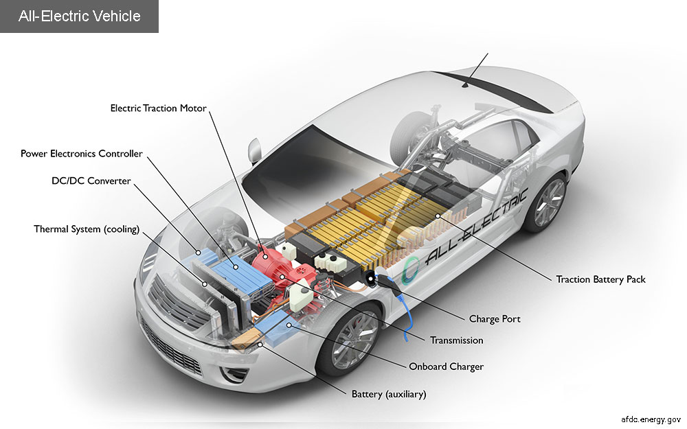
All-electric vehicles (EVs) have an electric motor instead of an internal combustion engine. The vehicle uses a large traction battery pack to power the electric motor and must be plugged into a charging station or wall outlet to charge. Because it runs on electricity, the vehicle emits no exhaust from a tailpipe and does not contain the typical liquid fuel components, such as a fuel pump, fuel line, or fuel tank.
All-electric vehicles (EVs) use a battery pack to store the electrical energy that powers the motor. EVs are sometimes referred to as battery electric vehicles (BEVs). EV batteries are charged by plugging the vehicle into an electric power source. Although electricity production may contribute to air pollution, the U.S. Environmental Protection Agency categorizes all-electric vehicles as zero-emission vehicles because they produce no direct exhaust or emissions.
Both heavy-duty and light-duty EVs are commercially available. EVs are typically more expensive than similar conventional and hybrid vehicles, although some cost can be recovered through fuel savings, a federal tax credit, or state incentives.
Components of an All-Electric Car
Battery (all-electric auxiliary): In an electric drive vehicle, the auxiliary battery provides electricity to power vehicle accessories.
Charge port: The charge port allows the vehicle to connect to an external power supply in order to charge the traction battery pack.
DC/DC converter: This device converts higher-voltage DC power from the traction battery pack to the lower-voltage DC power needed to run vehicle accessories and recharge the auxiliary battery.
Electric traction motor: Using power from the traction battery pack, this motor drives the vehicle’s wheels. Some vehicles use motor generators that perform both the drive and regeneration functions.
Onboard charger: Takes the incoming AC electricity supplied via the charge port and converts it to DC power for charging the traction battery. It monitors battery characteristics such as voltage, current, temperature, and state of charge while charging the pack.
Power electronics controller: This unit manages the flow of electrical energy delivered by the traction battery, controlling the speed of the electric traction motor and the torque it produces.
Thermal system (cooling): This system maintains a proper operating temperature range of the engine, electric motor, power electronics, and other components.
Traction battery pack: Stores electricity for use by the electric traction motor.
Transmission (electric): The transmission transfers mechanical power from the electric traction motor to drive the wheels.
Driving Range Today’s EVs generally have a shorter range (per charge) than comparable conventional vehicles have (per tank of gas). The efficiency and driving range of EVs vary substantially based on driving conditions. Extreme outside temperatures tend to reduce range because more energy must be used to heat or cool the cabin. High driving speeds reduce range because of the energy required to overcome increased drag. Compared with gradual acceleration, rapid acceleration reduces range. Hauling heavy loads or driving up significant inclines also reduces range.
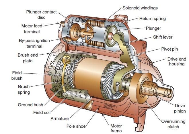
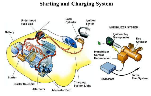
The starter motor is an electric motor that rotates your engine in order to allow the spark and fuel injection systems to begin the engine’s operation under its own power. Typically, the starter is a large electric motor and stator coil mounted to the bottom (generally to one side) of the vehicle’s transmission bell housing where it connects to the engine itself. The starter has gears which mesh with a large flywheel gear on the back side of the engine, which turns the central crankshaft. Because this is a lot of physical weight and friction to overcome, starter motors are generally powerful, high-speed motors and use an ignition coil to ramp up their power before engaging.
Components of the starting system
1. Battery
The automotive battery, also known as a lead-acid storage battery, is an electrochemical device that produces voltage and delivers current. In an automotive battery, we can reverse the electrochemical action, thereby recharging the battery, which will then give us many years of service. The purpose of the battery is to supply current to the starter motor, provide current to the ignition system while cranking, to supply additional current when the demand is higher than the alternator can supply and act as an electrical reservoir.
2. Ignition Switch
The ignition switch allows the driver to distribute electrical current to where it is needed. There are generally 5 key switch positions that are used:
1. Lock- All circuits are open ( no current supplied) and the steering wheel is in the lock position. In some cars, the transmission lever cannot be moved in this position. If the steering wheel is applying pressure to the locking mechanism, the key might be hard to turn. If you do experience this type of condition, try moving the steering wheel to remove the pressure as you turn the key. 2. Off- All circuits are open, but the steering wheel can be turned and the key cannot be extracted. 3. Run- All circuits, except the starter circuit, are closed (current is allowed to pass through). Current is supplied to all but the starter circuit. 4. Start- Power is supplied to the ignition circuit and the starter motor only. That is why the radio stops playing in the start position. This position of the ignition switch is spring loaded so that the starter is not engaged while the engine is running. This position is used momentarily, just to activate the starter. 5. Accessory- Power is supplied to all but the ignition and starter circuit. This allows you to play the radio, work the power windows, etc. while the engine is not running.
Most ignition switches are mounted on the steering column. Some switches are actually two separate parts;
* The lock into which you insert the key. This component also contains the mechanism to lock the steering wheel and shifter. * The switch which contains the actual electrical circuits. It is usually mounted on top of the steering column just behind the dash and is connected to the lock by a linkage or rod.
3. Neutral Safety Switch
This switch opens (denies current to) the starter circuit when the transmission is in any gear but Neutral or Park on automatic transmissions. This switch is normally connected to the transmission linkage or directly on the transmission. Most cars utilize this same switch to apply current to the backup lights when the transmission is put in reverse. Standard transmission cars will connect this switch to the clutch pedal so that the starter will not engage unless the clutch pedal is depressed. If you find that you have to move the shifter away from park or neutral to get the car to start, it usually means that this switch needs adjustment. If your car has an automatic parking brake release, the neutral safety switch will control that function also.
4. Starter Relay
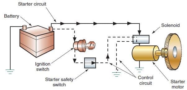
A relay is a device that allows a small amount of electrical current to control a large amount of current. An automobile starter uses a large amount of current (250+ amps) to start an engine. If we were to allow that much current to go through the ignition switch, we would not only need a very large switch, but all the wires would have to be the size of battery cables (not very practical). A starter relay is installed in series between the battery and the starter. Some cars use a starter solenoid to accomplish the same purpose of allowing a small amount of current from the ignition switch to control a high current flow from the battery to the starter. The starter solenoid in some cases also mechanically engages the starter gear with the engine.
5. Battery Cables
Battery cables are large diameter, the multistranded wire which carries the high current (250+ amps) necessary to operate the starter motor. Some have a smaller wire soldered to the terminal which is used to either operate a smaller device or to provide an additional ground. When the smaller cable burns, this indicates a high resistance in the heavy cable. Care must be taken to keep the battery cable ends (terminals) clean and tight. Battery cables can be replaced with ones that are slightly larger but never smaller.
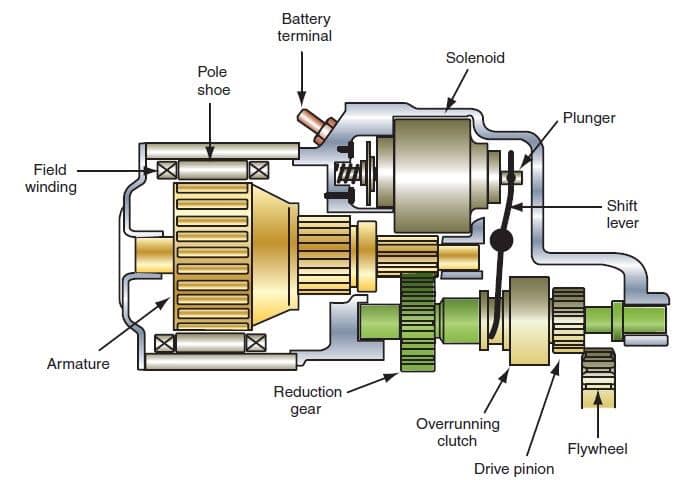
6. Starter Motor
The starter motor is a powerful electric motor, with a small gear (pinion) attached to the end. When activated, the gear has meshed with a larger gear (ring), which is attached to the engine. The starter motor then spins the engine over so that the piston can draw in a fuel/ air mixture, which is then ignited to start the engine. When the engine starts to spin faster than the starter, a device called an overrunning clutch (Bendix drive) automatically disengages the starter gear from the engine gear.
Working principles.
To make an engine start it must be turned at some speed, so that it sucks fuel and air into the cylinders, and compresses it.
The powerful electric starter motor does the turning. Its shaft carries a small pinion (gear wheel) which engages with a large gear ring around the rim of the engine flywheel.
In a front-engine layout, the starter is mounted low down near the back of the engine.
The starter needs a heavy electric current, which it draws through thick wires from the battery. No ordinary hand-operated switch could switch it on: it needs a large switch to handle the high current.
The switch has to be turned on and off very quickly to avoid dangerous, damaging sparking. So a solenoid is used – an arrangement where a small switch turns on an electromagnet to complete the circuit.
The starter switch is usually worked by the ignition key. Turn the key beyond the ‘ignition on’ position to feed current to the solenoid.
The ignition switch has a return spring so that as soon as you release the key it springs back and turns the starter switch off.
When the switch feeds current to the solenoid, the electromagnet attracts an iron rod.
The movement of the rod closes two heavy contacts, completing the circuit from the battery to the starter.
The rod also has a return spring -when the ignition switch stops feeding current to the solenoid, the contacts open and the starter motor stops.
The return springs are needed because the starter motor must not turn more than it has to in order to start the engine. The reason is partly that the starter uses a lot of electricity, which quickly runs down the battery.
Also, if the engine starts and the starter motor stays engaged, the engine will spin the starter so fast that it may be badly damaged.
The starter motor itself has a device, called a Bendix gear, which engages its pinion gear with the gear ring on the flywheel only while the starter is turning the engine. It disengages as soon as the engine picks up speed, and there are two ways by which it does so – the inertia system and the pre-engaged system.
The inertia starter relies on the inertia of the pinion gear – that is, its reluctance to begin to turn.
The pinion gear is not fixed rigidly to the motor shaft – it is threaded on to it, like a freely turning nut on a very coarse-thread bolt.
Imagine that you suddenly spin the bolt: the inertia of the nut keeps it from turning at once, so it shifts along the thread of the bolt.
When an inertia starter spins, the pinion moves along the thread of the motor shaft and engages with the flywheel gear ring.
It then reaches a stop at the end of the thread, begins to turn with the shaft and so turns the engine.
Once the engine starts, it spins the pinion faster than its own starter-motor shaft. The spinning action screws the pinion back down its thread and out of engagement.
The pinion returns so violently that there has to be a strong spring on the shaft to cushion its impact.
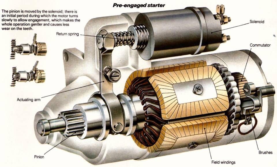
The violent engagement and disengagement of an inertia starter can cause heavy wear on the gear teeth. To overcome that problem the pre-engaged starter was introduced, which has a solenoid mounted on the motor.
There’s more to a car starter system: As well as switching on the motor, the solenoid also slides the pinion along the shaft to engage it.
The shaft has straight splines rather than a Bendix thread so that the pinion always turns with it.
The pinion gear is brought into contact with the toothed ring on the flywheel by a sliding fork. The fork is moved by a solenoid, which has two sets of contacts that close one after the other.
The first contact supplies a low current to the motor so that it turns slowly – just far enough to let the pinion teeth engage. Then the second contacts close, feeding the motor a high current to turn the engine.
The starter motor is saved from over-speeding when the engine starts by means of a freewheel clutch, like the freewheel of a bicycle. The return spring of the solenoid withdraws the pinion gear from engagement.
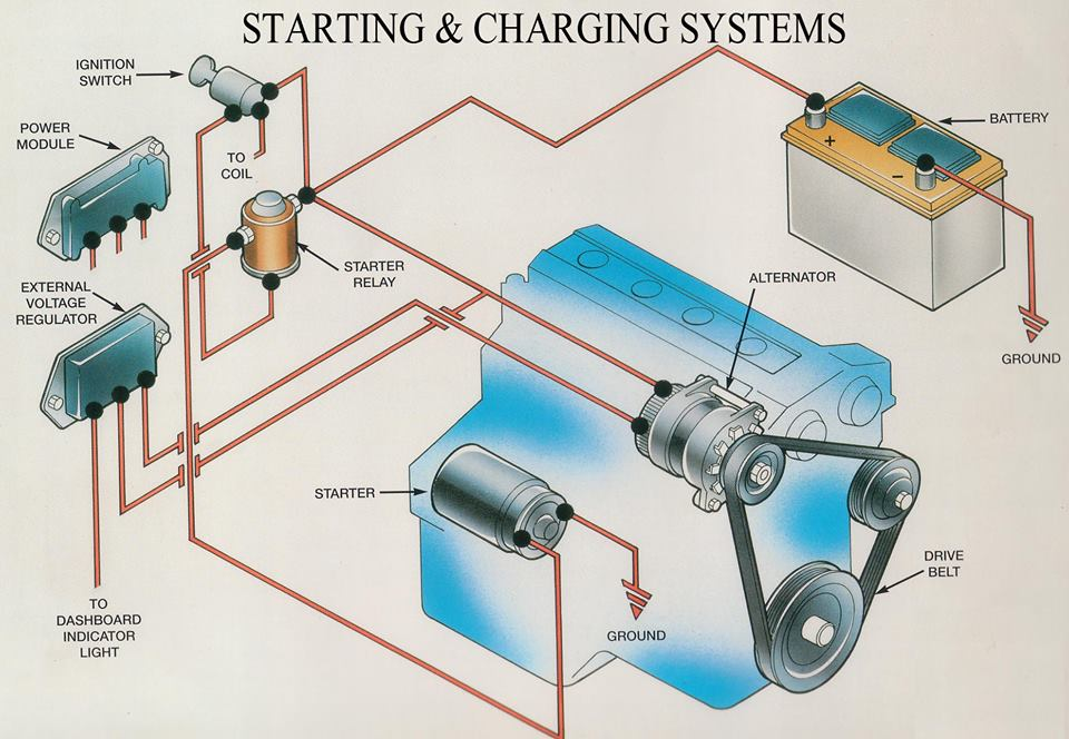
CHARGING SYSTEM: COMPONENTS, FUNCTIONS, WORKING PRINCIPLE AND DIAGNOSIS TIPS
The vehicle is equipped with many electrical devices to drive safely and comfortably. The vehicle requires electricity not only while driving but also while it stops.
Therefore, the vehicle has a battery for a power supply and a charging system to generate electricity by the engine running. The charging system supplies electricity to all the electrical devices and charges the battery.
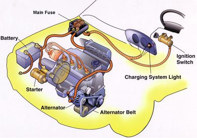
The Charging system is an important part of the electrical system. It provides electrical current for the lights, the radio, the heater, the engines electrical systems, and other electrical accessories. It also maintains the batteries in a charged state, recharging them as necessary.
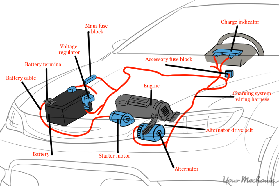
The charging system has three main components: the alternator, the voltage regulator, and the batteries.
The alternator generates electrical power to run accessories and to recharge the batteries. It is normally driven by a belt located off the crankshaft. Mechanical energy from the crankshaft is converted by the alternator into electrical energy for the batteries and accessories. The voltage regulator acts as an electrical traffic cop to control the alternator output. It senses when the batteries need recharging, or when the vehicles electrical needs increase and adjust the alternator’s output accordingly.
The batteries are a reservoir of chemical electrical power. Their primary purpose is to crank the engine. They also supply power to vehicle accessories when the electrical load is too great for the alternator alone.
Three-phase alternating current
(1) When a magnet rotates within a coil, a voltage will be created between both ends of the coil. This will give rise to an alternating current. (2) The relation between the current generated in the coil and the position of the magnet is as shown in the figure. The largest amount of current is generated when the N and S poles of the magnet are closest to the coil. However, the current flows in the opposite direction with each half-turn of the magnet. Current that forms a sine wave in this manner is called “single-phase alternating current”.
COMPONENTS AND FUNCTIONS
In general, the components of the charging system are composed of alternators and regulators. However, the charging system needs to add some additional components so that the electricity generated can be supplied to the battery and to all electrical loads safely and precisely. The component, consisting of;
1. Battery
The function of the battery is as a storage of electrical energy. Like a warehouse, the battery will store all the electrical energy generated by the alternator and then this stored electricity is removed when necessary.
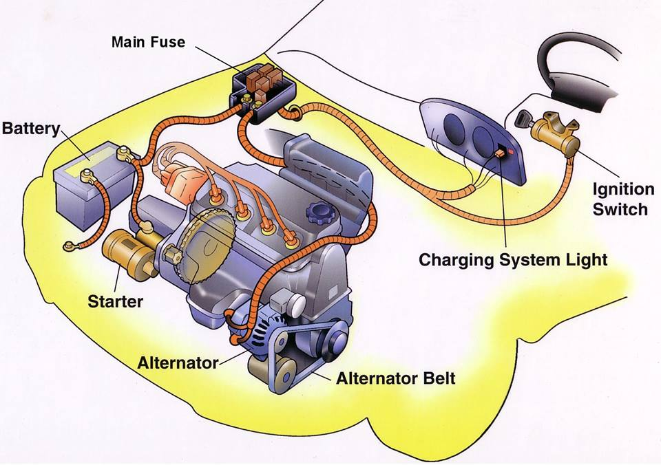
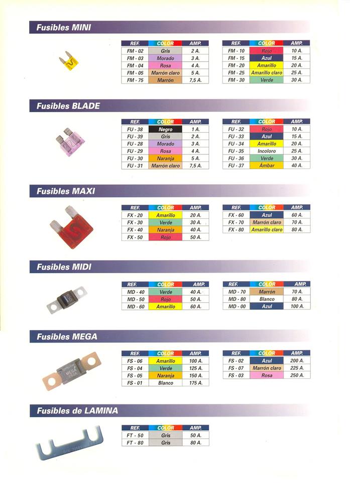
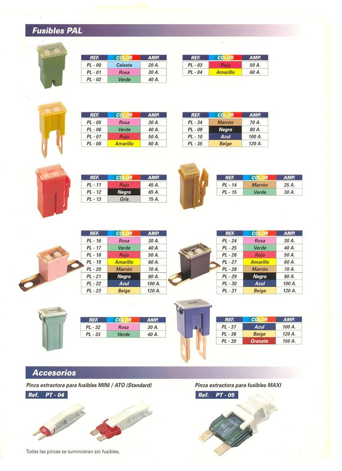
2. Fuse and Fusible links
Fuse and fusible links have different functions even though have the same shape. The fusible link can be called as the main fuse which is placed near the battery positive terminal. The function of this fuse is to protect the entire electrical system of the car from excessive currents. Generally, the fusible link has a capacity of up to more than 60 Ampere.
While the function of the fuse is as the safety of a series of specific electrical wiring, in conventional charging system there are two fuses with the same capacity (it’s about 10-15 Ampere). A fuse is used as a voltage regulator fuse and another fuse is used to secure the CHG and Voltage relay.
3. CHG Lights
CHG lamp or commonly also called “charging warning light” is an indicator light to indicate the present failure of the charging system. When the ignition key ON then this light will light up normally, as well as when the engine life of this lamp should turn on, if it is dead then it could mean the charging system failure.
4. Ignition key
The ignition key works as a switch. The charging system will be activated automatically when the engine is running, but to generate a magnetic field on the rotor coil must be done by a switch.
The ignition switch is used as a switch to connect and disconnect power (positive battery current) from battery to rotor coil. When the ignition key is ON, then the electricity from the battery to the coil rotor will be connected. However, when the ignition key is turned OFF then the power supply will be cut off. So it is not possible the alternator generates electricity when the ignition key is OFF even the engine crankshaft rotates.
5. Regulator
The function of the regulator is to regulate the voltage generated by the alternator. Why should it be there? because the voltage generated by the alternator depends on the engine’s RPM. This means that if the engine RPM is low, the alternator voltage is also low, but if the engine RPM is high then the alternator voltage is also high.
The regulator will be used to keep the voltage generated by the alternator not exceeding 14 volts even if the engine run in high RPM. This voltage setting aims to protect the electrical components of the vehicle to prevents over-voltage.
There are two types of regulators, namely type or conventional type and type of IC. The point type/conventional uses two coils to adjust the alternator output voltage. While the IC Regulator uses an IC circuit (Integrated Circuit) to regulate the output voltage.
6. Altenator
The function of the alternator is to convert a partial engine’s rotating energy into electricity. The alternator input comes from the engine pulley connected through a V belt, the rotation of the rotor will cause the intersection of the magnetic force line with the stator coil so that the electrons flow on the stator coil.
The electricity in the stator coil is not directly connected to the battery, but it must pass through the diode bridge to rectify the current. This is done because the current in the stator coil is AC (Alternate Current).
7. Charging Wire
The function of the charging wire is to connect every component of the charging system, there are at least two types of wires: standard wire and B + wire. The standard wire has a small diameter like the car’s electrical wiring in general, the function of this wire is connecting each terminal on the entire charging system.
While the B + wire has a larger diameter than the standard wire and almost matches the stater wire. The function of this wire is to connect the terminal B alternator with Battery.
WORKING PRINCIPLE
The flow of electricity in the charging system
Electricity in each position of the ignition switch.
Ignition switch ACC or LOCK
Ignition switch ON (when the engine is not running)
When the ignition switch is in the ON position, current flows from the battery to the alternator. The reason for this is as follows. The alternator generally used for the vehicle generates electricity by rotating the magnet. The magnet is not the permanent magnet but the electromagnet that generates magnetic force by flowing electricity inside. Therefore, it is necessary to supply electricity to the alternator before starting the engine to prepare for generating electricity.
Ignition switch ON (when the engine is running)
FUNCTIONS OF ALTERNATOR
The alternator plays a major role in the charging system. The alternator has three functions of generating electricity, rectifying current and regulating voltage.
(1) Generation Transmitting the engine revolution to the pulley via the v-ribbed belt turns the electromagnetic rotor, generating alternating current in the stator coil.
(2) Rectification Since the electricity generated in the stator coil is alternating current, this cannot be used for the DC electric devices installed on the vehicle. To use the alternating current, the rectifier is used to rectify the alternating current into direct current.
(3) Regulation of voltage IC regulator regulates the generated voltage to make the voltage constant even when the alternator speed or the amount of current flowing into the electric devices change.
CHARGING SYSTEM DIAGNOSIS
The following general information has been assembled as a guide for charging system diagnosis. Refer to the appropriate Original Equipment Manufacturer’s service manual for specific information pertaining to charging system diagnostic procedures and safety precautions for your vehicle.
BENCH TESTING
If an alternator test bench is available, follow the procedures found in the bench tester’s instruction manual to conduct an alternator performance test. This test will determine if the alternator output is within its performance specification, preventing unnecessary alternator replacement. If the alternator output is within specification during bench testing, resolve problems in the remainder of the vehicle’s charging circuit and other electrical circuits that may affect charging circuit performance. Refer to the appropriate vehicle manufacturer’s service manual for the procedures and circuit schematics necessary to identify and correct additional charging circuit problems. If the test bench results show the alternator’s output performance to be out of specification, replace the alternator. Follow the vehicle manufacturer’s recommended procedures to inspect the remainder of the charging circuit and other electrical circuits that may affect charging circuit performance.
NOTE: If the bench test identifies the regulator as defective, it may be possible to replace the regulator (internal or external) and return the alternator to service. If the regulator is replaced and the alternator returned to service, follow the vehicle manufacturer’s recommended procedures to inspect the remainder of the charging system and other electrical circuits that may affect charging circuit performance. Whether or not a test bench was used to determine the condition of the alternator, the following Helpful Tips have been assembled to help isolate conditions that may affect charging circuit performance.
HELPFUL TIPS
1. What is the condition of the battery? • A visual inspection and a performance test of the battery must always be performed before inspecting the charging system. The battery must be fully charged (12.6 volts) and the battery cables, terminals, and casein good, clean condition. This includes the frame and body grounds as well (refer to Battery Visual Inspection and Performance Testing).
2. Does a charge lamp, amperage (amp) gauge or voltmeter indicate a charging system problem?
Charge Lamp:
• Ignition ON engine not running – The charge lamp should illuminate. • Ignition ON engine running – The charge lamp should illuminate briefly then turn OFF. • Weak Battery – A weak battery can cause the charge lamp to illuminate during high amperage draw. • Low Idle – A low idle can cause the charge lamp to illuminate dimly. • Poor Wiring – Corroded, broken, loose or frayed wires/ connections could cause the charge lamp to illuminate during idle. • Open Charge Lamp – Some charging systems will not properly operate if the charge lamp bulb fails.
Amp Gauge:
• Ignition ON engine not running – The amp gauge should read zero or slightly below. • Ignition ON engine running – The amp meter should display a current output above zero. It will display a different level of charge depending on what electrical circuits are operating. A negative charge indicates the battery is discharging more quickly than the charging system can supply current. • Wires and connectors – Corroded, broken, loose or frayed wires/connections could cause zero or erratic readings on the gauge.
Voltmeter:
• Ignition ON and engine not running – Gauge readings should be between 12.0 and 12.6 volts with the ignition ON and the engine not running. Readings below 12 volts could indicate insufficient charging, low battery, corroded, broken, loose or frayed wires/connections. • Ignition ON and engine running – Gauge readings should be between 13.0 and 14.5 volts with the ignition ON and the engine running. A reading exceeding 14.5 volts could indicate a bad battery, failed regulator or poor wire connections. A reading below 13.2 volts could indicate a failed alternator or corroded, broken, loose or frayed wires/connections.
3. Are any fuses open?
• Check the fuses in all the fuse box(es). An open fuse indicates circuit problem(s) that may have an effect on the charging circuit. Check the owner’s manual or the manufacturer’s service manual for the location of each fuse box.
4. Is the fusible link(s) open?
• There may be several fusible links controlling battery voltage to the vehicle’s electrical circuits. If a fusible link is open, the supply voltage will be completely lost to all electrical systems or to the electric circuit(s) that the open fusible link controls. Check the owner’s manual or the manufacturer’s service manual for the location of each fusible link.
5. Is the alternator’s drive belt tension within specification?
• Too loose – If the drive belt is too loose, it will slip around the pulley causing the alternator to charge irregularly or not at all. • Too tight – If the drive belt is too tight, internal bearing damage will cause premature alternator failure.
6. Are the alternator’s drive belt in good condition and the proper size?
• Worn or too narrow – If the alternator’s drive belt is worn or too narrow, it will slip around the pulley, causing the alternator to charge irregularly or not at all. • New drive belt – The life of a new alternator drive belt is approximately 10 minutes. It is important to check and adjust the belt’s tension to the “used” specification after the initial 10 minutes of operation.
7. Has the vehicle been modified or additional equipment installed after it left the factory?
• Accessories – Non-factory accessories such as phones, computer outlets, televisions, refrigerators, stereo equipment or lights, among others, can overburden alternator performance and cause premature failure. • Improper accessory installation – Improper accessory installation procedures can cause charging problems. Some of these problems may include poor ground points, loose connections or improper wiring.
8. Has any work been performed on the vehicle?
• Electrical ground points – Check the ground circuits between the battery and engine and also from the vehicle body to the frame for high resistance. Many times when a vehicle has been repaired, the ground point(s) are disturbed or not re-secured properly. • Multiple electrical grounds – With multiple ground vehicles, each electrical circuit is assigned to one or more ground points. The poor ground at one ground point may cause feedback through another ground point causing unusual circuit activity.
El fusible está diseñado para proteger las partes más importantes de un sistema eléctrico del sobrecalentamiento y los daños relacionados como lo vimos en artículos anteriores. Cuando ocurre una sobretensión de la corriente, el alambre que se encuentra al interior del fusible se quema y corta la conexión con el circuito.
Aunque suena fácil y entendible existen muchas dudas al respecto de los fusibles y en el presente artículo vamos a resolver muchas de estas dudas, esperamos solucionar la mayoría de ellas.
¿Puedo provocar una avería aún mayor por cambiar el fusible? No es posible, lo único que puede pasar es que el fusible vuelva a fundirse, el sistema volverá a quedar inutilizado hasta tanto se resuelva el corto.
¿Cómo sé si la avería de la que me está avisando es grave o no? Será una avería grave probablemente un cortocircuito si el fusible se ha fundido y, nada más cambiarlo, se vuelve a fundir.
¿Funcionará el sistema sobre el que actúa el fusible en caso de que éste se funda? No, en caso que el fusible en cuestión es el que activa el airbag, el sistema queda inoperante, y sin los sistemas que controle este mismo fusible. Al cambiar el fusible el sistema vuelve a funcionar, pero si se rompe de nuevo volverá a quedar inoperante.
¿Cuándo debo acudir al taller? Lo recomendable es que se acuda siempre al taller, aunque usted haya cambiado este elemento puede volver a fundirse, es importante revisar el circuito para revisas que causo el fallo del fusible, que por lo general es un corto.
¿Y si pongo un fusible de mayor amperaje del que debe llevar? Es posible que se provoque otra avería grave en el sistema, o que afecte ciertos componentes. Por ejemplo, si el fusible corresponde al del motor del elevavidrios, lo más posible es que este se dañe.
¿Dónde comprarlos? En tiendas de repuestos, en centros del automóvil, en las grandes superficies o en los talleres oficiales.
¿Por qué tantos colores? Tienen una mera función identificativa: los naranjas son de 5A; los rojos, de 10A; los azules, de 15A; los amarillos, de 20A; los blancos, de 25, los verdes, de 30.