| 010 | Ignition | RPM 1/min | Load % | Throttle valve angle (Potentiometer) % | Ignition Angle (Actual) °KW | | | |
| 011 | Ignition | RPM 1/min | Coolant Temperature °C | Intake air temperature °C | Ignition Angle (Actual) °KW | | | |
| 012 | Distributor Adjustment | RPM 1/min | Load % | No. of crankshaft tooth at camshaft flank low->high XX | No. of cranckshaft tooth at camshaft flank low/high XX | | | |
| 013 | | | | | | | | |
| 014 | Misfire recognition | RPM 1/min | Last % | Misfire counter N | Misfire recognitrion Activated/ Locked | | | |
| 015 | Misfire recognition | Counter Cyl 1 N | Counter Cyl 2 N | Counter Cyl. 3 N | Misfire recognitrion Activated/ Locked | | | |
| 016 | Misfire recognition | Counter Cyl.. 4 N | Counter Cyl.. 5 N | Counter Cyl.. 6 N | Misfire recognitrion Activated/ Locked | | | |
| 017 | Misfire recognition | Counter Cyl.. 7 N | Counter Cyl.. 8 N | Counter Cyl.. 9 N | Misfire recognitrion Activated/ Locked | | | |
| 018 | Load/RPM Window misfire recognition | Lower RPM limit N | Upper RPM limit N | Lower RPM limit % | Upper RPM limit % | | | |
| 019 | Misfire recognition | Counter Cyl. 10 N | Counter Cyl. 11 N | Counter Cyl. 12 N | Misfire recognitrion Activated/ Locked | | | |
| 020 | Knock Control | Ignition angle retard Cyl. 1 °KW | Ignition angle retard Cyl. 2 °KW | Ignition angle retard Cyl. 3 °KW | Ignition angle retard Cyl.4 °KW | | | |
| 021 | Knock Control | Ignition angle retard Cyl. 5 °KW | Ignition angle retard Cyl. 6 °KW | Ignition angle retard Cyl. 7 °KW | Ignition angle retard Cyl.8 °KW | | | |
| 022 | Knock Control | RPM 1/min | Load % | Ignition angle retard Cyl. 1 °KW | Ignition angle retard Cyl. 2 °KW | | | |
| 023 | Knock Control | RPM 1/min | Last % | Ignition angle retard Cyl. 3 °KW | Ignition angle retard Cyl. 4 °KW | | | |
| 024 | Knock Control | RPM 1/min | Last % | Ignition angle retard Cyl. 5 °KW | Ignition angle retard Cyl. 6 °KW | | | |
| 025 | Knock Control | RPM 1/min | Last % | Ignition angle retard Cyl. 7 °KW | Ignition angle retard Cyl. 8 °KW | | | |
| 026 | Knock Control, KS Voltage | Cyl.. 1 V | Cyl.. 2 V | Cyl.. 3 V | Cyl.. 5 V | | | |
| 027 | Knock Control, KS Voltage | Cyl.. 5 V | Cyl.. 6 V | Cyl.. 7 V | Cyl.. 8 V | | | |
| 028 | Test Knock sensor, short trip | RPM 1/min | Load % | Coolant Temperature °C | Result Test ON /Test OFF/ Sys. OK / Sys. not OK | | | |
| 029 | | | | | | | | |
| 030 | Oxygen Sensor Status Bank 2 | Bank 1, sensor 1 | Bank 1, sensor 2 | Bank 2, sensor 1 | Bank 2, sensor 2 | | | |
| 030 | Oxygen Sensor Status Bank 1 | Bank 1, sensor 1 | Bank 1, sensor 2 | | | | | |
| 031 | Oxygen Sensor Voltage Bank 2 | Bank 1, sensor 1 V | Bank 1, sensor 2 V | Bank 2, sensor 1 V | Bank 2, sensor 2 V | | | |
| 031 | Oxygen Sensor Voltage Bank 1 | Bank 1, sensor 1 V | Bank 1, sensor 2 V | | | | | |
| 031 | Linear Oxygen Sensor Bank 2 | Lambda actual value Bank 1 | Lambda Specified Value Bank 1 | Lambda actual value Bank 2 | Lambda actual value Bank 2 | | | |
| 031 | Linear Oxygen Sensor Bank 1 | Lambda actual value Bank 1 | Lambda Specified Value Bank 1 | | | | | |
| 032 | Oxygen sensor learning values (Valor Máximo) Bank 2 | Bank 1, sensor 1, idle % | Bank 1, sensor 1, partial load % | Bank 2, sensor 1, idle % | Bank 2, sensor 1, partial load % | | | |
| 032 | Oxygen sensor learning values (Valor Máximo) Bank 1 | Bank 1, sensor 1, idle % | Bank 1, sensor 1, partial load % | | | | | |
| 033 | Lambda Control Value Bank 2 | Bank 1, control value % | Bank 1, Oxygen sensor voltage V | Bank 2, control value % | Bank 2, knock sensor voltage V | | | |
| 033 | Lambda Control Value Bank 1 | Bank 1, control value % | Bank 1, Oxygen sensor voltage V | | | | | |
| 033 | Linear Oxygen sensor Value Bank 2 | Bank 1, control value % | Bank 1, sensor voltage before cat. converter of a broad band sensorc V | Bank 2, control value % | Bank 2, sensor voltage before cat. converter of a broad band sensor V | | | |
| 034 | Oxygen Sensor aging test Bank 1 or Bank 3 Before Catalytic Converter Short trip | RPM 1/min | Exhaust gas / cat. converter temperature °C | Length of period S | Result Test ON/Test OFF/ B1-S1 OK/B1-S1 not OK Or B3-S1 OK /B3-S1 not OK | | | |
| 034 | Oxygen Sensor aging test Bank 1 or Bank 3 Before Catalytic Converter for linear oxygen sensor Short trip | RPM 1/min | Dynamic factor | Length of period S | Result Test ON/Test OFF/ B1-S1 OK/B1-S1 not OK Or B3-S1 OK /B3-S1 not OK | | | |
| 035 | Oxygen Sensor aging test Bank 2 or Bank 4 Before Catalytic Converter Short trip | RPM 1/min | Exhaust gas / cat. converter temperature °C | Length of period S | Result Test ON/Test OFF/ B2-S1 OK/B1-S1 not OK Or B4-S1 OK /B4-S1 not OK | | | |
| 035 | Oxygen Sensor aging test Bank 2 or Bank 4 Before Catalytic Converter for linear oxygen sensor Short trip | RPM 1/min | Dynamic factor | Length of period S | Result Test ON/Test OFF/ B2-S1 OK/B1-S1 not OK Or B4-S1 OK /B4-S1 not OK | | | |
| 036 | Oxygen sensor readiness after catalytic converter , short trip Bank 2 | Bank 1, sensor 2 | Result Test ON/Test OFF/ B1-S2 OK/B1-S2 not OK or B3-S2 OK/B3-S2 not OK | Bank 2, sensor 2 | Result Test ON/Test OFF/ B2-S2 OK/B2-S2 not OK or B4-S2 OK/B4-S2 not OK | | | |
| 036 | Oxygen sensor readiness after catalytic converter , short trip Bank 1 | Bank 1, sensor 2 | Result Test ON/Test OFF/ B1-S2 OK./B1-S2 not OK. | | | | | |
| 037 | Oxygen sensors short trip | Last % | Bank 1: Oxygen sensor voltage after cat. Converter V | Bank 1: TV shift ms | Result Test ON/Test OFF/ Sys. OK/Sys. not OK | | | |
| 037 | Linear Oxygen sensors short trip | Last % | Bank 1: Oxygen sensor voltage after cat. Converter V | Bank 1: D Lambda | Result Test ON/Test OFF/ Sys. OK/Sys. not OK | | | |
| 038 | Oxygen sensors short trip Bank 2 | Last % | Bank 2: Oxygen sensor voltage after cat. Converter V | Bank 1: TV shift ms | Result Test ON/Test OFF/ Sys. OK/Sys. not OK | | | |
| 038 | Linear Oxygen sensors short trip Bank 2 | Last % | Bank 2: Oxygen sensor voltage after cat. Converter V | Bank 1: D Lambda | Result Test ON/Test OFF/ Sys. OK/Sys. not OK | | | |
| 039 | Sensor exchange after Catalytic Converter, short trip | Air mass g/s | Bank 1: sensor voltage V | Bank 2 sensor voltage V | Result Text:Test ON/Test OFF/ Sys OK/Sys. not OK | | | |
| 040 | Oxygen Sensor heaters resistor combined wires and heaters Bank 2 | Heater resistor Banks 1+2, sensor 1 Ω | Condition Heater before cat. ON/ Heater before cat. OFF | Heater resistors Banks 1+2, sensor 2 [Ω | Condition Heater before cat. ON/ Heater before cat. OFF | | | |
| 041 | Oxygen Sensor heater Bank 1 | Resistor Bank 1, sensor 1 Ω | Condition or duty cycle Heater before cat. ON/ Heater before cat. OFF or sensor 1 [%] | Resistors Bank 1, Sensor 2 Ω | Condition Heater after cat. ON/ Heater after cat. OFF | | | |
| 042 | Oxygen Sensor heater Bank 2 | Resistor Bank 2, sensor 1 Ω | Condition or duty cycle Heater before cat. ON/ Heater before cat. OFF or sensor 1 [%] | Resistors Bank 2, Sensor 2 Ω | Condition Heater after cat. ON/ Heater after cat. OFF | | | |
| 043 | Oxygen sensor ageing after Catalytic Converter, linear oxygen sensor, short trip Bank 1 | RPM 1/min | Exhaust gas / cat. converter temperature °C | Oxygen sensor voltage V | Result Test ON/Test OFF/ B1-S2 OK/B1-S2 not OK or B3-S2 OK/B3-S2 not OK | | | |
| 044 | Oxygen sensor ageing after Catalytic Converter, linear oxygen sensor, short trip Bank 2 | RPM 1/min | Exhaust gas / cat. converter temperature °C | Oxygen sensor voltage V | Result Test ON/Test OFF/ B2-S2 OK/B2-S2 not OK or B4-S2 OK/B4-S2 not OK | | | |
| 045 | NOX memory Catalytic Converter Bank 1, short trip | Factor memory entry NOx | Result Test ON/Test OFF/ Sys. OK/Sys. not OK | Factor memory entry NOx | Result Test ON/Test OFF/ Sys. OK/Sys. not OK | | | |
| 046 | Catalytic Converter conversion test Bank 1 or Bank 3, short trip | RPM 1/min | Cat. converter temperature °C | Measuring value cat. Converter conversion | Result Test ON/Test OFF/ Cat B1 OK/ Cat B1 not OK or Cat B3 OK/ Cat B3 not OK | | | |
| 047 | Catalytic Converter conversion test Bank 2 or Bank 4, short trip | RPM 1/min | Cat. converter temperature °C | Measuring value cat. Converter conversion | Result Test ON/Test OFF/ Cat B2 OK/ Cat B2 not OK or Cat B4 OK/ Cat B4 not OK | | | |
| 048 | Thermal Catalytic Converter diagnosis Bank 1, short trip | Operating system BDE - | Number of test steps - | Exothermal temperature increase °K | Result Test ON/Test OFF/ Sys. OK/Sys. not OK | | | |
| 049 | Thermal Catalytic Converter diagnosis Bank 2, short trip | Operating system BDE - | Number of test steps - | Exothermal temperature increase °K | Result Test ON/Test OFF/ Sys. OK/Sys. not OK | | | |
| 050 | RPM Increase / Systems without separation for rear window defroster /A/C readiness | RPM actual value 1/min | RPM specified value 1/min | Rear window defroster/ Request for A/C -- ON/ OFF | A/C compressor -- ON/ OFF/ decrease | | | |
| 050 | RPM Increase / Systems with separation for rear window defroster /A/C readiness | RPM actual value 1/min | RPM specified value 1/min | Rear window defroster/ Request for A/C -- ON/ OFF | A/C compressor -- ON/ OFF/ decrease | | | |
| 051 | RPM, shift initiations | RPM actual value 1/min | RPM specified value 1/min | Driving range (only for automatic transmission) 0-6 / (Idle, driving ranges 1-6) | Supply voltage V | | | |
| 052 | RPM Increase Systems with separation for rear window defroster /A/C readiness | RPM actual value 1/min | RPM specified value 1/min | A/C readiness ON/OFF | Rear window defroster ON/OFF | | | |
| 053 | RPM increase based on generator load | RPM (actual value) 1/min | RPM (specified value) 1/min | Voltage V | Generator load % | | | |
| 054 | Closed throttle position switch | RPM 1/min | Operating conditions (LL, TL, VL, SA, BA) | Throttle valve angle (Potentiometer) % | Throttle valve angle (Potentiometer) % | | | |
| 055 | Closed throttle position switch for E-Gas-systems | RPM 1/min | Operating conditions (LL, TL, VL, SA, BA) | Sensor 1 for accelerator pedal position % | Throttle valve angle (Potentiometer) % | | | |
| 056 | Idle air control | RPM 1/min | Idle air control | Current learning value for idle air control | Operating conditions | | | |
| 057 | Idle air control | RPM (actual value) 1/min | RPM (specified value) 1/min | Idle air control valve | Operating conditions | | | |
| 058 | Idle air control, pressure signal A/C compressor | RPM (actual value) 1/min | RPM (specified value) 1/min | A/C compressor ON/OFF/decreasing | Duty cycle pressure receiver % | | | |
| 059 | | RPM 1/min | Load % | Engine bearing 1 right ON/OFF | Engine bearing 2 left ON/OFF | | | |
| 060 | ESB adaption Vehicles with ESB | Throttle valve angle (potentiometer) % | Throttle valve angle (potentiometer) % | Operating condition (Idle, partial load, full load, deceleration enrichment, acceleration enrichment) | Adaption condition (ADP runs/ADP OK/ ADP ERROR = in emergency mode | | | |
| 060 | E-Gas adaption Vehicles with E-Gas | Throttle valve angle (potentiometer 1) % | Throttle valve angle (potentiometer 2) % | Electrically controlled throttle valve adaption status N | Operating condition ADP runs/ADP OK/ ERROR | | | |
| 061 | ESB/E-Gas Systems without separation for rear window defroster /A/C readiness | RPM 1/min | Supply voltage Ubat V | Triggering throttle valve control % If possible | Operating condition Condition fulfilled = 1; Condition not fulfilled = 0 | | | |
| 061 | ESB/E-Gas Systems with separation for rear window defroster /A/C readiness | RPM 1/min | Supply voltage Ubat V | Triggering throttle valve control % If possible | Operating condition Condition fulfilled = 1; Condition not fulfilled = 0 | | | |
| 062 | E-Gas, potentiometer voltage relationship U/Uref | Angle sensor 1 for throttle valve drive (0->100%) | Angle sensor 2 for throttle valve drive (0->100%) | Sensor 1 accelerator pedal position (0->100%) | Sensor 2 accelerator pedal position (0->100%) | | | |
| 063 | Kick-down adaption | Sensor 1 accelerator pedal position (0->100%) | Sensor 1 learned Kick-down point (0->100%) | Switch Kick-down | | | | |
| 064 | Throttle valve potentiometer adaption values | Potentiometer 1 lower adaption V | Potentiometer 2 1 lower adaption V | Emergency air gap potentiometer 1 V | | | | |
| 065 | | | | | | | | |
| 066 | Cruise control switched free for 4 position operating lever | Vehicle speed actual [km/h] | Switch positions | Vehicle speed specified [km/h] in 1 km/h-steps (only displayed when cruise control function is freely switched) | | | | |
| 066 | Cruise control switched free for 6 position operating lever | Vehicle speed actual [km/h] | Switch positions xxxxxxxx | Vehicle speed specified [km/h] in 1 km/h-steps (is only issued with freely switched cruise control function) | Switch positions For 6 position operating lever | | | |
| 067 | | | | | | | | |
| 068 | | | | | | | | |
| 069 | | | | | | | | |
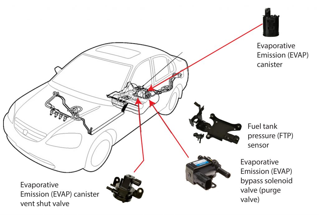
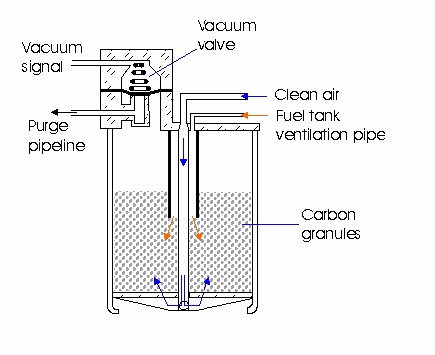
| 070 | Fuel tank venting and valve testing, short trip | Opening degree fuel tank ventilation Duty Cycle % | Lambda regular/ diagnostic value with active diagnose | Idle air control valve / diagnostic value with active diagnose % | Result Test ON/ Test OFF/ Fuel tank ventilation OK/ Fuel tank ventilation not OK. | | | |
| 071 | Fuel tank leak test, short trip | Condition reed contact Reed Open / Reed Closed | DTC Small leak/large leak | Test status System test/measurement/ measurement end | Result Test ON/ Test OFF/ Abort Syst. OK/ Syst. Not OK | | | |
| 072 | Tank leak test | | | | | | | |
| 073 | | | | | | | | |
| 074 | EGR regulator solenoid adaption | Null-Position V | Max. Stop V | Current potentiometer value V | Text Leak detection pump runs/ LDP OK/ ERROR | | | |
| 075 | EGR, short trip Systems with Temp.-sensor | Engine RPM [1/min] | EGR-Temp. Sensor °C | EGR temperature difference °C | Result Test ON/ Test OFF/ Syst. OK/ Syst. Not OK | | | |
| 075 | EGR, short trip Systems with intake manifold pressure sensor | Engine RPM [1/min] | Intake manifold pressure [mbar] | Intake manifold pressure difference [mbar] | Result Test ON/ Test OFF/ Syst. OK/ Syst. Not OK | | | |
| 075 | EGR, for map adaption short trip Systems with intake manifold pressure sensor | Pressure difference diagnostics EGR phase 1 and 2 [hPa] | Pressure difference diagnostics EGR phase 2 and 3 [hPa] | Pressure difference diagnostics EGR phase 1 and 3 [hPa] | Result Test ON/ Test OFF/ Syst. OK/ Syst. Not OK | | | |
| 076 | EGR for pressure systems | Engine RPM [1/min] | Intake manifold pressure [mbar] | Opening degree (U/Uref) EGR potentiometer % | Duty cycle EGR valve % | | | |
| 076 | EGR for air mass system | Engine RPM [1/min] | Last % | Opening degree (U/Uref) EGR potentiometer % | Duty cycle EGR valve % | | | |
| 076 | EGR map adaption | Actual EGR value – potentiometer without offset V | Correction factor in the upper opening range % | Correction factor in the lower opening range % | Status Test OFF / Leak detection pump runs/ LDP OK/ ERROR | | | |
| 077 | Test secondary air injection system, short trip, Bank 1 Systems with conventional oxygen sensor | RPM 1/min | Engine air mass g/sec | Air mass secondary air injection system g/sec | Result Test ON/ Test OFF/ Abort-- Syst. OK/ Syst. Not OK | | | |
| 077 | Test secondary air injection system, short trip, Bank 1 Systems with linear oxygen sensor | RPM 1/min | Engine air mass g/sec | relative Air mass | Result Test ON/ Test OFF/ Abort-- Syst. OK/ Syst. Not OK | | | |
| 078 | Test secondary air injection system, short trip Bank 2 Systems with conventional oxygen sensor | RPM 1/min | Engine air mass g/sec | Air mass secondary air injection system g/sec | Result Test ON/ Test OFF/ Abort-- Syst. OK/ Syst. Not OK | | | |
| 078 | Test secondary air injection system, short trip, Bank 2 Systems with linear oxygen sensor | RPM 1/min | Engine air mass g/sec | relative Air mass | Result Test ON/ Test OFF/ Abort-- Syst. OK/ Syst. Not OK | | | |
| 079 | | | | | | | | |
| 080 | Control module identification (display shown at NA-No. 63) | Manufacturer’s code and marking | Manufacturing date | Manufacture’s change status | Manufacturer’s test stand number. | | | |
| 081 | Control module identification (display shown at NA-No. 63) | Vehicle identification number | Limit No or serial number | Type test number | | | | |
| 082 | Control module identification (display shown at NA-No. 63) | Flash tool code | Flash date | Hardware | Software | | | |
| 083 | Control module identification | | | | | | | |
| 084 | Control module identification | | | | | | | |
| 085 | Control module identification | | | | | | | |
| 090 | Camshaft adjustment Intake | RPM 1/min | Adjustment ON/OFF | Adjustment Bank 1 [°KW] | Adjustment Bank 2 [°KW] | | | |
| 090 | Camshaft adjustment Exhaust | RPM 1/min | Adjustment ON/OFF | Adjustment Bank 1 [°KW] | Adjustment Bank 2 [°KW] | | | |
| 090 | Continuous camshaft adjustment Exhaust Bank 1 | RPM 1/min | Duty cycle % | Adjustment specified [°KW] | Adjustment actual [°KW] | | | |
| 091 | Camshaft adjustment Intake Bank 1 | RPM 1/min | Last % | Adjustment ON/OFF | Adjustment actual [°KW] | | | |
| 091 | Continuous camshaft adjustment, Intake Bank 1 | RPM 1/min | Duty cycle % | Adjustment specified [°KW] | Adjustment actual [°KW] | | | |
| 092 | Camshaft adjustment Intake Bank 2 | RPM 1/min | Last % | Adjustment ON/OFF | Adjustment actual [°KW] | | | |
| 092 | Continuous camshaft adjustment, Intake Bank 2 | RPM 1/min | Duty cycle % | Adjustment specified [°KW] | Adjustment actual [°KW] | | | |
| 093 | Camshaft adaption values Intake Bank 2 | RPM 1/min | Last % | Phase position [Deviation from correct position (shift of camshaft position sensor on shaft), 0 = Position OK] Bank 1[The phase position is displayed only when the phase adaptation was successfully concluded] [°KW] | Phase position Bank 2 [°KW] | | | |
| 093 | Continuous camshaft adaption values | Phase position intake Bank 1 [°KW] | Phase position intake Bank 2 [°KW] | Phase position exhaust Bank 1 [°KW] | Phase position exhaust Bank 2 [°KW] | | | |
| 094 | Camshaft adjustment Banks 1 and 2 Intake, short trip | RPM 1/min | Camshaft adjustment Text: Camshaft position ON / Camshaft position OFF | Test result Bank 1 Test ON/ Test OFF/ Syst. OK/ Syst. Not OK | Test result Bank 2 Test ON/ Test OFF/ Syst. OK/ Syst. Not OK | | | |
| 094 | Continuous camshaft adjustment Banks 1 and 2 intake, short trip | RPM 1/min | Phase position intake [°KW] | Test result Bank 1 Test ON/ Test OFF/ Syst. OK/ Syst. Not OK | Test result Bank 2 Test ON/ Test OFF/ Syst. OK/ Syst. Not OK | | | |
| 095 | Intake manifold change-over /Single step change-over | Engine RPM [1/min] | Last % | Coolant Temperature °C | Status ein/aus | | | |
| 095 | Intake manifold change-over /Multi-step change-over | Engine RPM [1/min] | Last % | Coolant Temperature °C | Status Off /step 1/step 2 | | | |
| 096 | Camshaft adjustment Banks 1 and 2 Exhaust, short trip | Engine RPM [1/min] | Camshaft adjustment Text: Camshaft position ON / Camshaft position OFF | Test result Bank 1 Test ON/ Test OFF/ Syst. OK/ Syst. Not OK | Test result Bank 2 Test ON/ Test OFF/ Syst. OK/ Syst. Not OK | | | |
| 096 | Continuous camshaft adjustment Banks 1 and 2 Exhaust, short trip | RPM 1/min | Phase position exhaust [°KW] | Test result Bank 1 Test ON/ Test OFF/ Syst. OK/ Syst. Not OK | Test result Bank 2 Test ON/ Test OFF/ Syst. OK/ Syst. Not OK | | | |
| 097 | Intake air change-over / Snow flap | RPM 1/min | Last % | Temperature / Pressure [°C]/[mbar] | Intake air change-over ON/ OFF | | | |
| 098 | Continuous camshaft adjustment Exhaust Bank 2 | RPM 1/min | Duty cycle % | Adjustment specified [°KW] | Adjustment actual [°KW] | | | |
| 099 | Shut-off l-Regulation (via basic setting) (for compatibility reasons with older systems) | RPM 1/min | Coolant Temperature °C | Lambda regulation [%] | Lambda regulation ON/OFF | | | |
| 100 | eadiness code (for compatibility reasons with older systems) | Ready bits / 1= not concluded -- 0= concluded | Coolant temperature | Time since engine start | OBD-Status | | | |
| 101 | Fuel injection Systems with Air mass measurement | RPM 1/min | Last % | Mean injection time (at deceleration = 0) ms | Air mass g/s | | | |
| 101 | Fuel injection Systems with intake manifold pressure measurement | RPM 1/min | Last % | Mean injection time (at deceleration = 0) ms | Intake manifold pressure mbar | | | |
| 102 | Fuel injection | RPM 1/min | Coolant Temperature °C | Intake air temperature °C | Mean injection time ms | | | |
| 103 | Air-shrouded fuel injectors, short trip | RPM 1/min | Air mass idle air control [g/s] | LFR-Offset adaptation N | Result Test ON/Test OFF/ l injector OK /l injector not OK | | | |
| 104 | Start adaptation values | Start engine temperature [°C] | Temperature adaptation factor 1 [%] | Temperature adaptation factor 2 [%] | Temperature adaptation factor 3 [%] | | | |
| 105 | Cylinder shut off | RPM 1/min | Last % | Coolant Temperature °C | Shut-off (ON = Cylinder shut-off active; OFF = Cylinder shut-off not active) | | | |
| 106 | | | | | | | | |
| 107 | Lambda regulation, short trip | RPM 1/min | Lambda regulation Bank 1 (average value) [%] | Lambda regulation Bank 1 (average value) [%] | Result Test ON/ Test OFF/ Syst. OK/ Syst. Not OK | | | |
| 108 | | | | | | | | |
| 109 | | | | | | | | |
| 110 | Load, full load enrichment | RPM 1/min | Coolant Temperature °C | Average injection time ms | Throttle valve angle (Potentiometer) % | | | |
| 111 | Boost pressure control | Adaption value boost pressure control RPM range 1 [%] | Adaption value boost pressure control RPM range 2 [%] | Adaption value boost pressure control RPM range 3 [%] | Adaption value boost pressure control RPM range 4 [%] | | | |
| 112 | Exhaust gas temperature | Exhaust gas temperature Bank 1 [°C] | Enrichment factor sensor Bank 1 [%] | Exhaust gas temperature Bank 2 [%] | Enrichment factor sensor Bank 2 [%] | | | |
| 113 | Last | RPM 1/min | Last % | Throttle valve angle (Potentiometer) % | Air pressure Mbar | | | |
| 114 | Boost pressure control | Specified load without correction [%] | Specified load after correction [%] | Actual load [%] | Duty cycle Boost pressure valve [%] | | | |
| 115 | Boost pressure control | RPM 1/min | Last % | Boost pressure specified value [mbar] | Boost pressure actual value [mbar] | | | |
| 116 | Boost pressure control | RPM 1/min | Correction factor fuel [%] | Correction factor coolant temperature [%] | Correction factor intake air temperature [%] | | | |
| 117 | Boost pressure control | RPM 1/min | Gas pedal position [%] | Throttle valve angle [%] | Boost pressure specified [mbar] | | | |
| 118 | Boost pressure control | RPM 1/min | Intake air temperature °C | Duty cycle boost pressure control valve [%] | Boost pressure before throttle valve [mbar] | | | |
| 119 | Boost pressure control | RPM 1/min | Actual adaption value boost pressure control valve [%] | Duty cycle boost pressure control valve [%] | Boost pressure before throttle valve [mbar] | | | |
| 120 | ASR/FDR | RPM 1/min | Specified moment ASR/FDR [Nm] | Engine moment [Nm] | Status (ASR active/ASR not active) | | | |
| 121 | | | | | | | | |
| 122 | Transmission | RPM 1/min | Specified moment ASR/FDR [Nm] | Engine moment [Nm] | (Engine intervention /no intervention) | | | |
| 123 | Reserved for CAN Bus signals | | | | | | | |
| 124 | Reserved for CAN Bus signals | | | | | | | |
| 125 | CAN Bus signals / see CAN-Product Description Manual | Transmission This corresponds with the desired sequence. Should there be no participant available a gap will remain at this place. | ABS32 | Instrument cluster32 | A/C32 | | | |
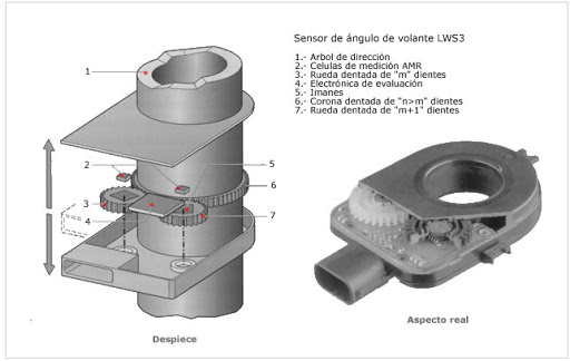
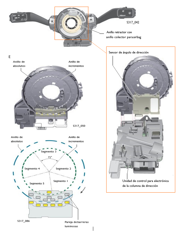
| 126 | CAN Bus signals | ADR 32 | LWS 32 | Airbag32 | Electrical wiring32 | | | |
| 127 | CAN Bus signals | All wheel32 | Level | Steering wheel | | | | |
| 128 | CAN Bus signals | | | | | | | |
| 129 | CAN Bus signals | | | | | | | |
| 130 | Map cooling (coolant filling), Short trip | Temperature Engine outlet [°C] | Temperature Radiator outlet [°C] | Duty cycle Thermostat [%] | Test ON/ Test OFF/ Syst. OK/ Syst. Not OK | | | |
| 131 | Map cooling | Temperature Engine outlet [°C] | Temperature Engine outlet (specified) [°C] | Temperature Radiator outlet [°C] | Duty cycle Thermostat [%] | | | |
| 132 | Map cooling | Temperature Radiator outlet [°C] | Temperature difference Engine and radiator outlet °C | Heater pre-run potentiometer % | Status cooling | | | |
| 133 | | | | | | | | |
| 134 | Temperature | Oil temperature [°C] | Ambient temperature [°C] | Intake air temperature [°C] | Engine outlet temperature [°C] | | | |
| 135 | Coolant fan control, short trip | Temperature Radiator outlet (specified) [°C] | Duty cycle Coolant fan actuation 1 [%] | Duty cycle Coolant fan actuation 2 [%] | Test ON/ Test OFF/ Syst. OK/ Syst. Not OK | | | |
| 136 | Relay for coolant fan actuation | Relay 1 ON / OFF | Relay 2 ON / OFF | Relay 3 ON / OFF | Relay 4 ON / OFF | | | |
| 137 | A/C requirements | AC-inlet ON / OFF | Compressor ON / OFF | High pressure switch or Pressure of A/C system ON / OFF or [bar] | Fan request from A/C system [%] | | | |
| 140 | Pressure control valve, short trip | Duty cycle DSV [%] | Rail pressure specified [bar] | Rail pressure actual [bar] | Test ON/ Test OFF/ Syst. OK/ Syst. Not OK | | | |
| 141 | Fuel supply system | Rail pressure regulator [bar] | Regulator rail pressure system | Regulator rail pressure system residual portion | Status rail pressure system | | | |
| 142 | | | | | | | | |
| 143 | | | | | | | | |
| 144 | | | | | | | | |
| 145 | Exhaust gas temperature sensor, short trip | Exhaust gas temperature from model Bank 1 [°C] | Exhaust gas temperature sensor measured Bank 1 [°C] | Exhaust gas temperature sensor measured Bank 2 [°C] | Test ON/ Test OFF/ Syst. OK/ Syst. Not OK | | | |
| 146 | | | | | | | | |
| 147 | Charge movement flap for BDE | Charge movement flap Actual position [%] | Charge movement flap Specified position [%] | Offset value of potentiometer voltage LBK (V) | Adaptation condition ADP runs/ ADP OK/ Error (in emergency running mode) | | | |
| 160 | Individual cylinder recognition/ Individual cylinder control | Normal Lambda control starting point cylinder 1 | Normal Lambda control starting point cylinder 2 | Normal Lambda control starting point cylinder 3 | Normal Lambda control starting point cylinder 4 | | | |
| 161 | Individual cylinder recognition/ Individual cylinder control | Normal Lambda control starting point cylinder 5 | Normal Lambda control starting point cylinder 6 | Normal Lambda control starting point cylinder 7 | Normal Lambda control starting point cylinder 8 | | | |
