¿Qué es un Turbocargador de Geometría Variable, y cómo funciona?

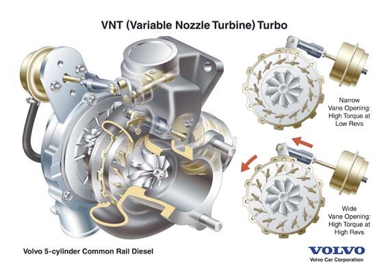
Los turbocompresores de geometría variable (VGT o turbocompresores de geometría variable) es un término que se le asigna alagunos turbos en su mayoría a diesel. Los VGT tienen turbinas con álabes que se mueven según las necesidades del motor al que están conectados.

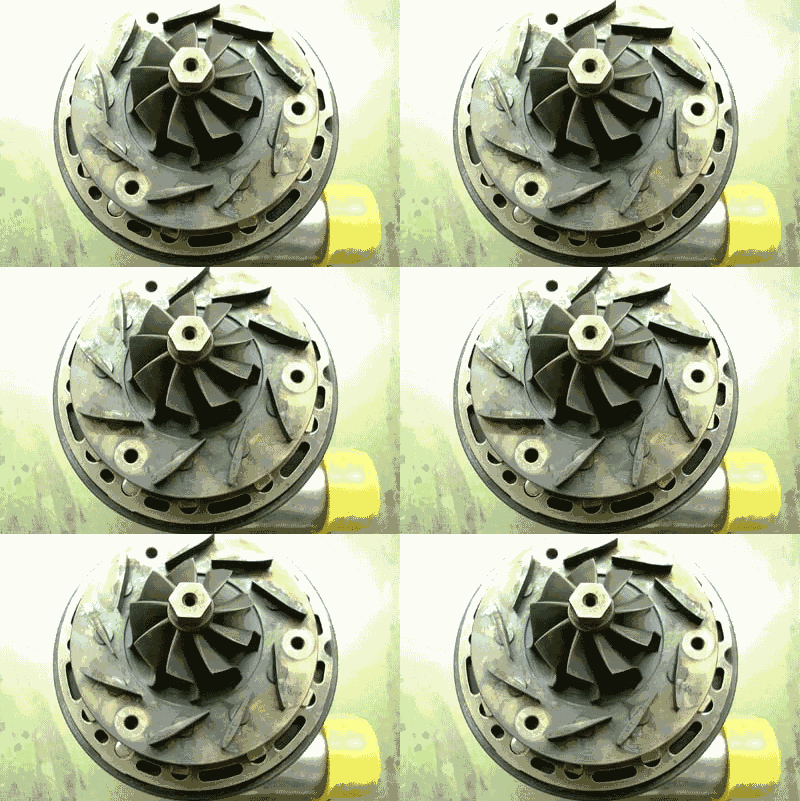
La forma en que se mueven los alabes depende del diseño de VGT; algunos fabricantes los diseñan para pivotar y otros para deslizarlos. Los primeros VGT regulaban las posiciones de las piezas utilizando actuadores de presión o vacío, pero la mayoría de los diseños actuales utilizan unidades de control electrónico para determinar las posiciones de las piezas.

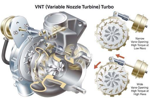
Cuando se alteran las posiciones de los alabes, cambia la geometría de la carcasa de la turbina. Estos cambios afectan la velocidad de la turbina giratoria, lo que permite optimizarla para el rendimiento del motor.

Cuando la velocidad del motor es baja, el espacio en el turbo se expande, disminuyendo la velocidad del aire que fluye a través de la turbina. Cuando la velocidad del motor es alta, el espacio en el turbo se restringe, aumentando la velocidad del aire que fluye a través de la turbina.

Es importante recordar que los VGT cambian la velocidad de la turbina, no la cantidad de aire de escape. La cantidad de aire de escape nunca cambia.

Los VGT se crearon para trabajar con sistemas EGR para controlar las emisiones y son esenciales para la regeneración del filtro de partículas diésel (DPF). Durante la regeneración del DPF, la velocidad del aire debe controlarse por completo para que la temperatura del aire de escape sea lo suficientemente alta como para quemar la materia acumulada en el filtro.

Un turbo de geometría variable (VGT) es una solución de potencia compleja y costosa que prevalece especialmente en los motores diésel. Un VGT tiene un anillo de álabes de forma aerodinámica en la carcasa de la turbina que puede alterar su relación de área a radio para igualar las revoluciones del motor. A bajas revoluciones, la relación área-radio crea más presión y velocidad para acelerar el turbo de manera más efectiva. A revoluciones más altas, la relación aumenta para dejar entrar más aire. El resultado es un rango de impulso más amplio y menos retraso.

Ventajas

• Curva de par amplia y plana. Turbocompresor eficaz en un rango de RPM muy amplio.
• Requiere un solo turbo, lo que simplifica una configuración turbo secuencial en algo más compacto.

Desventajas

• Por lo general, solo se usa en aplicaciones diésel donde los gases de escape son más bajos para que las paletas no se dañen con el calor.
• Para las aplicaciones de gasolina, el costo generalmente las mantiene fuera, ya que se deben usar metales exóticos para mantener la confiabilidad. La tecnología se ha utilizado en el Porsche 997, aunque existen muy pocos motores de gasolina VGT como resultado del costo asociado.

¿Qué es el Turbocompresor Eléctrico de Audi y cómo funciona?

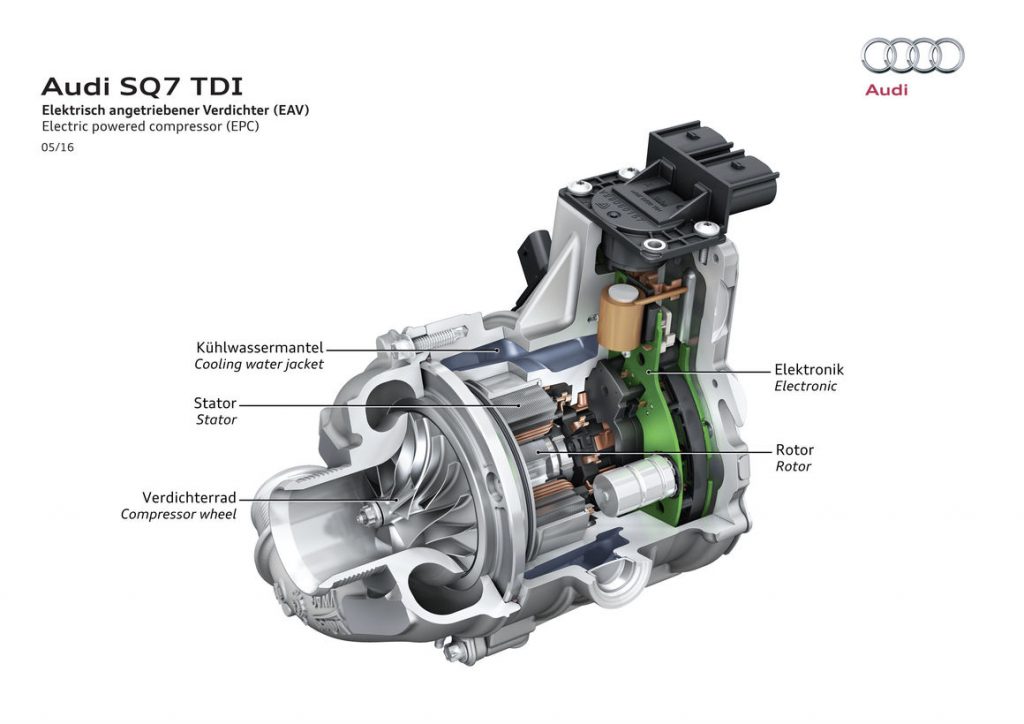
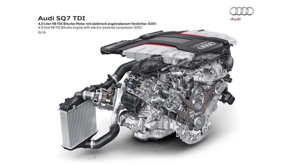
El turbocompresor eléctrico es un dispositivo mecánico eléctrico que ayuda a optimizar la eficiencia y reducir el turbolag a bajas revoluciones en el automóvil, incorpora un motor eléctrico que hace la funciona de la turbina y un compresor está instalado en el sistema de admisión de aire que entra al motor, antes del turbo principal y del intercooler y normalmente es accionado a un régimen de giro determinado por el fabricante en este caso Audi

Sin embargo, a muy bajas revoluciones, cuando salimos de un semáforo, por ejemplo, el aire que es enviado al turbo principal no sería suficiente como para activarlo, entonces el turbo eléctrico entra en funcionamiento y empuja el aire con mucha más fuerza en el motor, eliminando el Turbolag.

Las ventajas de la instalación de un sobrealimentador eléctrico residen en su total independencia de los gases de escape, modificándose el sistema eléctrico debido a la necesidad de tensiones de trabajo de 48 voltios como mínimo.

La sobrealimentación eléctrica promete importantes mejoras en consumos, rendimientos más eficaces del motor y un optimo desempeño de las normas ambientales y de gases, Estos principios básicos de la evolución de los motores actuales permiten tener un mejor mercado automotriz.

Turbolag

Uno de los principales problemas a los que se enfrentan los fabricantes de vehículos, independientemente del tipo de sobrealimentación que incorporan, son las prestaciones a bajo régimen debido al famoso TURBOLAG (tiempo de reacción) tiempo que transcurre desde que pisamos el acelerador hasta que notamos el empuje total del motor, siendo esta idea tan antigua como el propio turbo.

Características

Las cifras que ofrece el sobrealimentador eléctrico de Audi son demoledores, alcanzando una velocidad de giro de 70.000 rpm en apenas centésimas de segundo.

Ésta es su principal ventaja como elemento complementario al diseño de doble turbocompresor en serie, pues el retraso del turbo – efecto lag – es totalmente contrarrestado por la velocidad que alcanza la turbina eléctrica en muy poco tiempo.

Pero las ventajas de este sobrealimentador eléctrico van más allá, y es que esta pequeña turbina es capaz de alcanzar valores de presión relativa de 2,4 bares, consiguiendo unos registros más que interesantes para llenar cada uno de los cilindros.

¿Qué es el Turbo Lag en el auto y cómo se produce?

Para ir entendiendo el concepto rápidamente determinamos que el Lag (retraso) es un lapso de tiempo (retraso de respuesta), que transcurre desde que se pisa el acelerador hasta que la fuerza se transmite a las ruedas y se genera un movimiento

El lag se genera cuando los gases de escape entran en contacto con la inercia de las propias turbinas que conforman el sistema del turbo, ya que su peso hace que no puedan funcionar de manera inmediata. Pero también por el tiempo que transcurre hasta que las turbinas giran lo suficiente como para que su presión sea capaz de empujar el vehículo.

Es decir, cuando la turbina gira con lentitud, el motor se comporta como si no llevara turbo, hasta que éste alcanza la velocidad de giro necesaria para comprimir el aire de admisión.

En algunos motores, con el turbocompresor muy grande, cuesta mucho mover la turbina cuando no está girando o cuando lo hace despacio, por lo que los gases de escape necesitan vencer una fuerte inercia.

Para solucionarlo, se utilizan turbocompresores cada vez más pequeños; turbos con materiales muy ligeros pero que resistan muy bien el calor, como la cerámica o el titanio, o turbocompresores de geometría variable. o en su defecto turbo compresores electricos como el que incorporó AUDI, o el actualmente desarrollado por Garrett

¿Qué es una válvula de alivio (Wastegate) y cómo funciona en el turbocargador?

Una valvula de alivio o Wastegate es un dispositivo integrado en un turbocompresor que controla la presión de sobrealimentación máxima permitida.  La válvula de descarga es un componente en un turbocompresor que desvía los gases de la turbina. La función principal de la válvula de descarga es regular la presión de sobrealimentación óptima en los sistemas de turbocompresor para proteger el turbocompresor y el motor. El desvío de los gases de escape ajusta la velocidad de la turbina, que en sintonía ajusta la velocidad de rotación del compresor.

Es en esta etapa que la rueda de la turbina traduce la energía térmica (energía potencial) del escape del motor en energía mecánica. Si el flujo de escape se desvía de manera que no fluya a través de la rueda de la turbina de un turbocompresor, entonces su energía potencial no es convertida por la turbina. En pocas palabras, la reducción del flujo de escape a través de la turbina reduce y / o controla la presión de refuerzo. En una palabra,

Tipos de Válvulas de alivio

Hay dos tipos de alivios; interno y externo. Una compuerta de desechos interna está integrada en el conjunto de la carcasa de la turbina. Se instala una válvula de descarga externa en el tubo ascendente de escape entre el colector de escape y la entrada de la carcasa de la turbina. En cualquier caso, se requiere un actuador para operar la válvula de válvula de descarga. Cuando se abre la válvula, el flujo de escape se desvía de su trayectoria normal a través de la rueda de la turbina y, en su lugar, sale directamente al tubo de escape.

En función del modo de apertura, se distinguen dos variantes de válvulas de descarga:

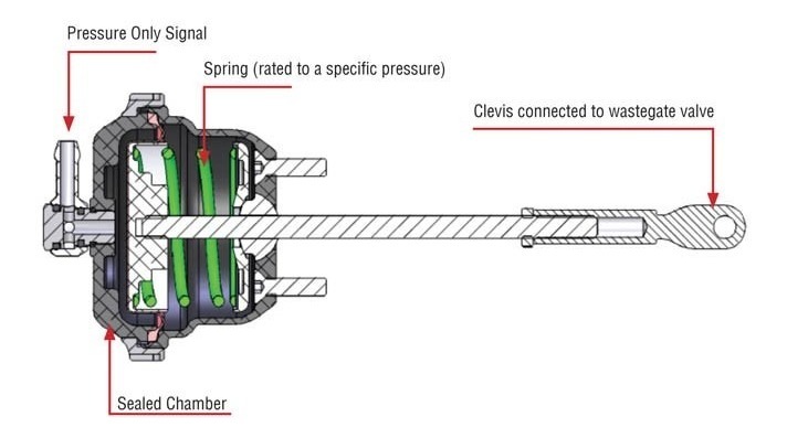
  • Válvula de descarga de tipo «push . En estas válvulas de descarga, la apertura es accionada mediante un muelle. Este muelle, tarado a una determinada fuerza, aprieta el pistón de la válvula manteniéndola cerrada. Cuando la presión en la admisión vence la fuerza del muelle, se abre la válvula para permitir la salida del aire comprimido.
  • Válvula de descarga de tipo «pull».En las válvulas de descarga de tipo jalar, la apertura es accionada por medio de una membrana en vez de por muelles. A diferencia de la versión tipo “push”, estas válvulas tienen la ventaja de que no necesitan regulación ya que se adaptan automáticamente a cualquier valor de presión. Se trata de un modelo más sofisticado y más caro que la opción tipo “push”, que permite un funcionamiento más optimizado y suave. Las válvulas de descarga tipo “pull” aseguran la estanqueidad máxima al ralentí y no sufren fugas bajo ningún rango de presión de soplado del turbo. 

Válvula de descarga blow off

Como es la que expulsa el aire sobrante al exterior, . También suele llamarse válvula de descarga atmosférica, precisamente por lanzar al aire a presión a la atmósfera. Este tipo de válvulas es característica de los sonidos realizados al revolucionar el vehículo

Válvula de descarga de bypass

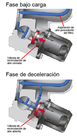
Una válvula de compresión bypass, también llamada válvula de recirculación, no saca el aire sobrante fuera. En su caso lo envía a la admisión, pero antes del turbo. Es decir, en la parte de donde el turbo saca el aire para luego presurizarlo y meterlo en el motor. Es importante que lo envíe a un lugar donde el caudalímetro pueda medir bien el aire que entra realmente. De lo contrario la mezcla de aire y combustible será incorrecta.

Control de la Válvula de Alivio Wastegate

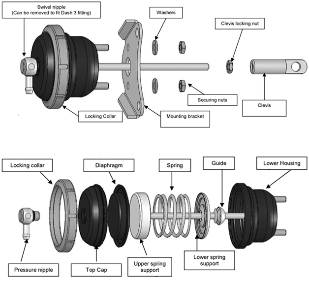
Uno de los métodos más simples para controlar una válvula de descarga es mediante la presión del múltiple de admisión (presión absoluta del múltiple o MAP). Una línea o manguera conecta el colector de admisión a un actuador de válvula de descarga, que es esencialmente un diafragma mecánico y un dispositivo de resorte. El resorte dentro del actuador de la válvula de descarga mantiene la válvula en la posición cerrada. Al igual que la presión del colector de admisión (presión de refuerzo), también lo hace la presión en el actuador de la válvula de descarga, aplicando una fuerza al diafragma. Cuando la fuerza ejercida sobre el diafragma excede la fuerza del resorte, la válvula de descarga comienza a abrirse. A medida que cae la presión de refuerzo, el resorte cierra la compuerta de desechos.

Una implementación más moderna del control de la válvula de descarga es mediante un actuador eléctrico; Esto se está volviendo cada vez más popular en motores turboalimentados. En lugar de depender de una presión múltiple o una fuente de vacío, estas compuertas de desagüe cuentan con un solenoide eléctrico que es controlado directamente por el PCM y ajusta la posición de la válvula de compuerta de desagüe.

WASTEGATES Y TURBOCOMPRESORES DE GEOMETRÍA VARIABLE (VGT)

Tradicionalmente (con excepciones), un turbocompresor de geometría variable (VGT) no requiere el uso de una valvula de alivio, ya que el impulso se controla perpetuamente por la posición de los álabes en la carcasa de la turbina. El un VGT ajusta físicamente el tamaño efectivo de la carcasa de la turbina al aumentar o disminuir las presiones de los gases de escape que actúan sobre la rueda de la turbina. En lugar de desviar los gases de escape alrededor de la rueda de la turbina, un VGT simplemente abre las paletas, simulando un efecto similar al de una válvula de descarga. 

A medida que se cierran las paletas, aumenta la energía de escape que actúa sobre la rueda de la turbina. Este rango de movimiento se utiliza para proporcionar una respuesta deseable del turbocompresor mientras se controlan las características de rendimiento y la presión de refuerzo máxima en todas las condiciones.

¿Qué es un supercargador y como funciona en el motor del AUTOMÓVIL?

SUPERCHARGER: TYPES, METHODS AND WORKING PRINCIPLE

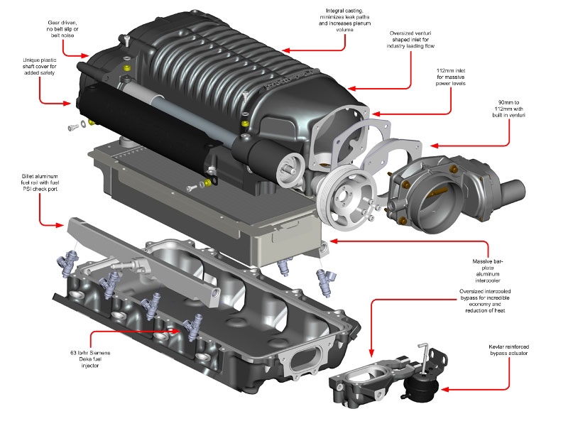
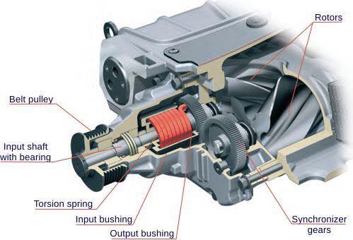
Superchargers are basically compressors/blowers which takes air at normal ambient pressure & compresses it and forcefully pushes it into engine! Power to the compressor/ blower is transmitted from engine via the belt drive.

The addition of extra amount of air-fuel mixture into the cylinder increases the mean effective pressure of the engine. An increment in MEP makes the engine produce more power. In this way, adding a compressor to the engine makes it more efficient.

TYPES OF SUPERCHARGER

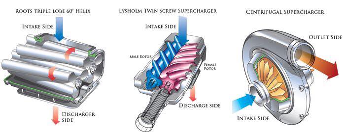
There are mainly two types of supercharger. The first one is known as positive displacement supercharger and other one is known as Dynamic supercharger. The basic difference between both of them is that the positive displacement supercharger maintains constant level of pressure at all engine speed whereas the dynamic supercharger delivers increasing pressure with increasing speed. This is basic fundamental difference between them. These superchargers further subdivided as given below.

1. POSITIVE DISPLACEMENT SUPERCHARGER:

Image may contain: text

As we discussed in early section that these superchargers deliver the same volume of charge at any engine speed or these superchargers are not depended on speed of the engine. The major types of positive displacement supercharger are root style and twin screw.

1. Root style
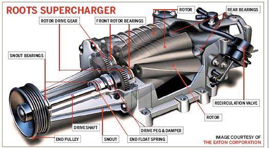
This design has two specially designed rotors which rotate in opposite direction (one is clockwise and other is anticlockwise) to compress the air. According to the rotor design this supercharger is further subdivided into two type: Two lob rotor, three lob, four lob rotors etc. As the rotor rotate, they trap the air by these lobs coming from suction side or inlet port and forced it towards discharge side or outlet port. The amount of air compressed is independent on the engine speed and each time this supercharger compresses the same amount of air.

Advantages:
 Simple design
 Best suited with high speed engine

Disadvantages:
 Pulsing airflow at low speed.
 Less efficiency.
 Heavy in weight.
 Create lots of heat due to friction.
 Back leakage at low speed.
 Provide same amount of air at both low and high RPM.

2. Twin screw supercharger
As the name implies, this type of supercharger have two screws which rotate in different direction. One of the screw rotate clockwise and other one is anticlockwise direction. The working of this supercharger is same as root type. It also sucks air from one side and delivered it to outlet port. This device provide smother air flow comparatively root style.

Advantages:

No photo description available.


 No back leakage problem.
 Provide smother air flow.

Disadvantages:
 High heat generation due to friction.
 Noisy in operation.

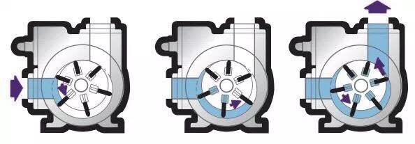
3. Vane type supercharger
A number of vanes are mounted on the drum of the supercharger. These vanes are pushed outwards via pre-compressed springs. This arrangement helps the vane to stay in contact with the inner surface of the body.
Now due to eccentric rotation, the space between two vanes is more at the inlet & less at the outlet. In this way, the quantity of air which enters at the inlet decreases it’s volume on its way to outlet. A decrease in volume results in increment of pressure of air. Thus, the mixture obtained at the outlet is at higher pressure than at the inlet.

2. DYNAMIC SUPERCHARGER:

No photo description available.

As we discussed earlier, these type of supercharger gives increasing air pressure as increasing engine speed. The supercharging effect in this type is highly depended on the engine speed. It also subdivided into following types.

1. Centrifugal Type


As the name implies this type uses centrifugal force to compress the air. The design of this supercharger is same as the centrifugal compressor. It has a impeller which is connected with the crankshaft with the help of belt drive. When the engine rotates, it makes rotate the impeller which sucks the air from one side. The centrifugal action acts on this air which increase its kinetic energy and delivery it to a diffuser. The air enter into the diffusion have high velocity at low pressure. The diffuser converts this high speed low pressure air to low speed high pressurized air. This high pressurized air then sent to the engine.

Advantages:
 It is small in size.
 High efficiency.

Disadvantages:
 The amount of air is not fixed.

2. Pressure wave 
3. Axial flow

METHODS OF SUPERCHARGING

No photo description available.

There are various other ways to force the air which doesn’t need extra power unlike compressors. The 2 most widely applied are –

• Ram effect supercharging 
Here, the inlet manifold is designed in such a way that the air gets automatically pushed into the cylinder. The air continuously tries into the cylinder but the intake valves open/close several times a second ! Every time the valve closes, the air just rams into it. This generates a pressure wave which travels in the opposite direction until it hits the plenum & gets reflected back.

Now if the resonant frequency of the plenum & engine matches, this pressure wave carries more air into the cylinder doing the work of a supercharger.

• Under piston supercharging –
This type of method is generally adopted in large marine engines. It utilizes the bottom side of the piston for compressing the air. With proper timing of valves, this system gives an adequate supply of compressed air, as there are 2 delivery strokes to each suction stroke of each stroke !

ADVANTAGES AND DISADVANTAGES OF SUPERCHARGER

Advantages of supercharging

1. Higher power output
2. Greater induction of charge mass
3. Better atomization of fuel
4. Better mixing of fuel and air
5. Better scavenging products
6. Better torque characteristics over whole range
7. Quick acceleration of vehicle
8. Complete and smooth combustion
9. Even fuel with poor ignition quality can be used
10. Improved cold starting
11. Reduced exhaust smoke
12. Reduced specific fuel consumption
13. Increased mechanical efficiency
14. Smooth operation and reduction in diesel knock tendency

Disadvantages of supercharging

1. Increased detonation tendency in SI engines
2. Increased thermal stress
3. Increased heat loss due to increased turbulence
4. Increased gas loading
5. Increased cooling requirements of the engine

TURBOCHARGER: COMPONENTS, WORKING PRINCIPLES, AND TYPES

A Turbocharger is a device that is used to increase the power of the engine or one can say the efficiency of an engine by increasing the amount of air entering into the combustion chamber. More air into the combustion chamber means more amount of fuel will be admitted into the cylinder and as a result, one will get more power from the same engine if the turbocharger is installed in it.

Very simply, a turbocharger is a kind of air pump taking air at ambient pressures (atmospheric pressure), compressing to a higher pressure and passing the compressed air into the engine via the inlet valves.

At the present time, turbos are used mainly on diesel engines, but there is now a move towards the turbocharging of production petrol engines.

The amount of engine that actually goes into the engine’s cylinder, compared with the theoretical amount if the engine could maintain the atmospheric pressure, is called volumetric efficiency and the aim of the turbocharger is to improve an engine’s volumetric efficiency by increasing density of the intake gas.

The turbocharger draws the air from the atmosphere and compresses it with the help of centrifugal compressor before it enters into the intake manifold at increased pressure. This results in more amount of air entering into the cylinders on each intake stroke. The centrifugal compressor gets power from the kinetic energy of the engine’s exhaust gases.

COMPONENTS OF TURBOCHARGER

The turbocharger has three main components
1. The turbine, which is almost a radial inflow turbine.
2. The compressor is almost a centrifugal compressor.
3. The center hub rotating assembly.

No photo description available.

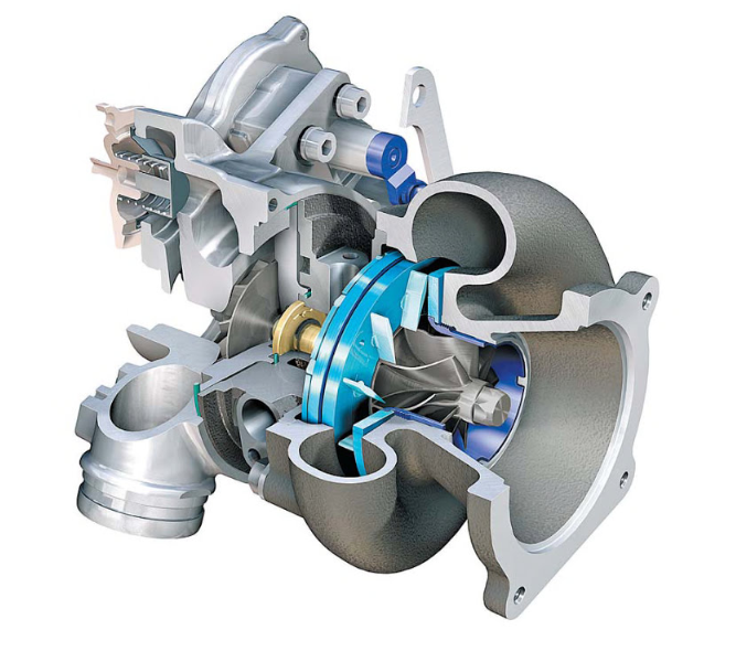
A turbocharger is made up of two main sections: the turbine and the compressor.

The turbine consists of a turbine wheel and turbine housing. It is the job of the turbine housing to guide the exhaust gas into the turbine wheel. The energy from the exhaust gas turns the turbine wheel, and the gas then exits the turbine housing through an exhaust outlet area.

The compressor also consists of two parts: the compressor wheel and the compressor housing. The compressor’s mode of action is opposite that of the turbine. The compressor wheel is attached to the turbine by a forged steel shaft, and as the turbine turns the compressor wheel, the high-velocity spinning draws in air and compresses it. The compressor housing then converts the high-velocity, low-pressure air stream into a high-pressure, low-velocity air stream through a process called diffusion. The compressed air is pushed into the engine, allowing the engine to burn more fuel to produce more power.

WORKING PRINCIPLE

A turbocharger mainly consists of two main sections: the turbine and the compressor. The turbine consists of a turbine wheel and the turbine housing whose purpose is to guide the exhaust gases into the turbine wheel. The kinetic energy of the exhaust gases gets converted into the mechanical after striking it on turbine blades. The exhaust outlet helps the exhaust gases to get exit from the turbine. The compressor wheel in the turbocharger is attached to a turbine with the help of steel shaft and as the turbine turns the compressor wheel, it draws the high-velocity, low-pressure air stream and converts it into high-pressure, low –velocity air stream. This compressed air is pushed into the engine with the more quantity of fuel and hence produce more power.

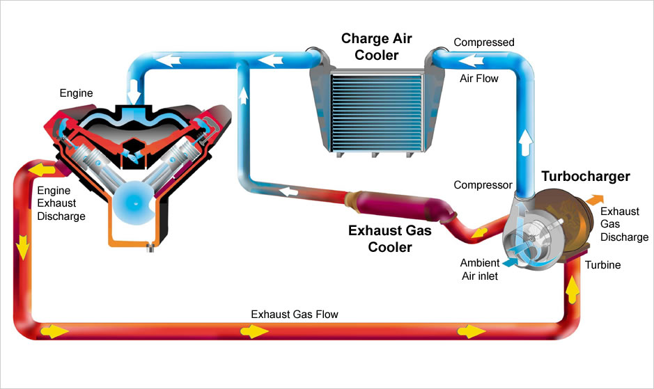
The waste exhaust gases of the engine are utilized to drive a turbine wheel, which is connected to a compressor wheel by a shaft. The compressor or air wheel sucks in air through the air filters and passes this into the engine.
As the waste gases are expelled from the engine, they are directed to the turbine or hot wheel of the turbo and so completes the cycle.

1. Capture

Instead of escaping through the exhaust pipe, hot gases produced during combustion flow to the turbocharger. The cylinders inside an internal combustion engine fire in sequence (not all at once), so exhaust exits the combustion chamber in irregular pulses.
Conventional single-scroll turbochargers route those irregular pulses of exhaust into the turbine in a way that causes them to collide and interfere with one another, reducing the strength of the flow. In contrast, a twin-scroll turbocharger gathers exhaust from pairs of cylinders in an alternating sequence.

2. Spin

The exhaust strikes the turbine blades, spinning them at up to 150,000 rpm. The alternating pulses of exhaust help eliminate turbo lag.

3. Vent

Having served their purpose, exhaust gases flow through an outlet to the catalytic converter, where they are scrubbed of carbon monoxide, nitrous oxides, and other pollutants before exiting through the tailpipe.

4. Compress

Meanwhile, the turbine powers an air compressor, which gathers cold, clean air from a vent and compresses it to 30 percent above atmospheric pressure, or nearly 19 pounds per square inch. Dense, oxygen-rich air flows to the combustion chamber.

The additional oxygen makes it possible for the engine to burn gasoline more completely, generating more performance from a smaller engine. As a result, the Twin Power engine generates 30 percent more power than a non-turbocharged one of the same sizes.

It follows the following process

1. The engine’s air intake sucks in cool air and sends to the compressor.
2. The compressor compresses the incoming air and heats it up. It then blows out the hot air.
3. The hot air cools down when passing through the heat exchanger and enters the cylinder’s air intake.
4. The cold air burns inside the combustion chamber at a faster rate because of carrying more oxygen.
5. Due to the burning of more fuel, the energy output will be bigger faster, and the engine will be able to send more power to the wheels.
6. Hot waste gasses will leave the chamber and blows past the turbine at the exhaust outlet.
7. The turbine rotates at a high speed and spins the compressor too as both are mounted on the same shaft.
8. The exhaust gasses leave the car through the exhaust pipe. They waste less energy than an engine not having a turbocharger.

TYPES OF TURBOCHARGER

1. Single-Turbo

Single turbochargers alone have limitless variability. Differing the compressor wheel size and turbine will lead to completely different torque characteristics. Large turbos will bring on high top-end power, but smaller turbos will provide better low-end grunt as they spool faster. There are also ball bearing and journal bearing single turbos. Ball bearings provide less friction for the compressor and turbine to spin on, thus are faster to spool (while adding cost).

Advantages
• A cost-effective way of increasing an engine’s power and efficiency.
• Simple, generally the easiest of the turbocharging options to install.
• Allows for using smaller engines to produce the same power as larger naturally-aspirated engines, which can often remove weight.

Disadvantages
• Single turbos tend to have a fairly narrow effective RPM range. This makes sizing an issue, as you’ll have to choose between good low-end torque or better high-end power.
• Turbo response may not be as quick as alternative turbo setups.

2. Twin-Turbo

Just like single turbochargers, there are plenty of options when using two turbochargers. You could have a single turbocharger for each cylinder bank (V6, V8, etc). Alternatively, a single turbocharger could be used for low RPM and bypass to a larger turbocharger for high RPM (I4, I6, etc). You could even have two similarly sized turbos where one is used at low RPM and both are used at higher RPM. On the BMW X5 M and X6 M, twin-scroll turbos are used, one on each side of the V8.

Advantages
• For parallel twin turbos on ‘V’ shaped engines, the benefits (and drawbacks) are very similar to single turbo setups.
• For sequential turbos or using one turbo at low RPM and both at high RPM, this allows for a much wider, flatter torque curve. Better low-end torque, but the power won’t taper at high RPM like with a small single turbo.

Disadvantages
• Cost and complexity, as you’ve nearly doubled the turbo components.
• There are lighter, more efficient ways of achieving similar results (as discussed below).

3. Twin-Scroll Turbo

A turbo is powered by exhaust gases that are redirected to spin turbine blades and force air into the engine. Now, an engine’s cylinders fire in sequence, meaning that exhaust gases enter the turbo in pulses. As you can probably imagine, these pulses can easily overlap and interfere with one another when powering the turbo, and a twin-scroll turbocharger solves this issue by using a divided-inlet turbine housing and a specific exhaust manifold that pairs the right cylinders to each scroll. In a four-cylinder vehicle, you can then have the first and fourth cylinders powering one scroll, and two and three powering another. This means that there are less pulse overlap and less lag.

Advantages
• More energy is sent to the exhaust turbine, meaning more power.
• A wider RPM range of effective boost is possible based on the different scroll designs.
• More valve overlap is possible without hampering exhaust scavenging, meaning more tuning flexibility.

Disadvantages
• Requires a specific engine layout and exhaust design (eg: I4 and V8 where 2 cylinders can be fed to each scroll of the turbo, at even intervals).
• Cost and complexity versus traditional single turbos.

4. Variable Geometry Turbocharger (VGT)

A variable geometry turbo (VGT) is an expensive and complex power solution that’s especially prevalent in diesel engines. A VGT has a ring of aerodynamically-shaped vanes in the turbine housing that can alter their area-to-radius ratio to match the revolutions of the engine. At low revs, area-to-radius ratio creates more pressure and velocity to spool up the turbo more effectively. At higher revolutions, the ratio increases to let in more air. The result is a wider boost range and less lag.

Advantages
• Wide, flat torque curve. Effective turbocharging at a very wide RPM range.
• Requires just a single turbo, simplifying a sequential turbo setup into something more compact.

Disadvantages
• Typically only used in diesel applications where exhaust gases are lower so the vanes will not be damaged by heat.
• For gasoline applications, the cost typically keeps them out as exotic metals have to be used in order to maintain reliability. The tech has been used on the Porsche 997, though very few VGT gasoline engines exist as a result of the cost associated.

5. Variable Twin-Scroll Turbocharger

A variable twin-scroll turbo combines a VGT with a twin-scroll setup, so at low revolutions, one of the scrolls is closed completely, forcing all the air into the other. This results in good turbo response and low-end power. As you speed up, a valve opens to allow air into the other scroll (this is a completely variable process, meaning the valve opens in small increments), you get good high-end performance. You get the sort of performance from a single turbo that you’d normally only be able to get from a twin-turbo set-up.

Advantages
• Significantly cheaper (in theory) than VGTs, thus making an acceptable case for gasoline turbocharging.
• Allows for a wide, flat torque curve.
• More robust in design versus a VGT, depending on the material selection.

Disadvantages
• Cost and complexity versus using a single turbo or traditional twin-scroll.
• The technology has been played with before (eg: quick spool valve) but doesn’t seem to catch on in the production world. There are likely additional challenges with technology.

6. Electric Turbochargers

A very recent development is the introduction of turbos with electric compressors. An example is BorgWarner’s booster, which is an electrically powered compressor. The compressor provides an instant boost to the engine until the turbocharger has spooled up enough. A similar version of this can be found in Audi’s SQ7. With the instant boost, lag becomes a thing of the past, but again, the system is expensive and complex. A compressor needs a motor, which in turn needs to be powered, so this is not a simple system to implement.

Advantages
• By directly connecting an electric motor to the compressor wheel, turbo lag and insufficient exhaust gases can be virtually eliminated by spinning the compressor with electric power when needed.
• By connecting an electric motor to the exhaust turbine, wasted energy can be recovered (as is done in Formula 1).
• A very wide effective RPM range with even torque throughout.

Disadvantages
• Cost and complexity, as you now must account for the electric motor and ensure it remains cool to prevent reliability issues. That goes for the added controllers as well.
• Packaging and weight become an issue, especially with the addition of a battery onboard, which will be necessary to supply sufficient power to the turbo when needed.
• VGTs or twin-scrolls can offer very similar benefits (though not at quite the same level) for a significantly lower cost.

Copyright © All rights reserved. | StoreCommerce by AF themes.
YouTube
YouTube
Instagram