CHARGING SYSTEM: COMPONENTS, FUNCTIONS, WORKING PRINCIPLE AND DIAGNOSIS TIPS
The vehicle is equipped with many electrical devices to drive safely and comfortably. The vehicle requires electricity not only while driving but also while it stops.
Therefore, the vehicle has a battery for a power supply and a charging system to generate electricity by the engine running. The charging system supplies electricity to all the electrical devices and charges the battery.
The Charging system is an important part of the electrical system. It provides electrical current for the lights, the radio, the heater, the engines electrical systems, and other electrical accessories. It also maintains the batteries in a charged state, recharging them as necessary.
The charging system has three main components: the alternator, the voltage regulator, and the batteries.
The alternator generates electrical power to run accessories and to recharge the batteries. It is normally driven by a belt located off the crankshaft. Mechanical energy from the crankshaft is converted by the alternator into electrical energy for the batteries and accessories.
The voltage regulator acts as an electrical traffic cop to control the alternator output. It senses when the batteries need recharging, or when the vehicles electrical needs increase and adjust the alternator’s output accordingly.
The batteries are a reservoir of chemical electrical power. Their primary purpose is to crank the engine. They also supply power to vehicle accessories when the electrical load is too great for the alternator alone.
Three-phase alternating current

(1) When a magnet rotates within a coil, a voltage will be created between both ends of the coil. This will give rise to an alternating current.
(2) The relation between the current generated in the coil and the position of the magnet is as shown in the figure. The largest amount of current is generated when the N and S poles of the magnet are closest to the coil. However, the current flows in the opposite direction with each half-turn of the magnet. Current that forms a sine wave in this manner is called “single-phase alternating current”.
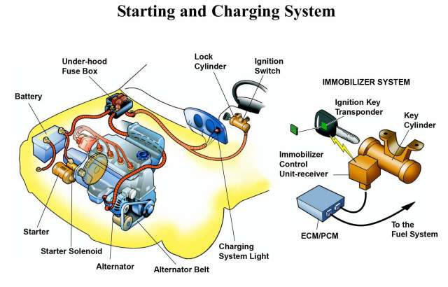
COMPONENTS AND FUNCTIONS
In general, the components of the charging system are composed of alternators and regulators. However, the charging system needs to add some additional components so that the electricity generated can be supplied to the battery and to all electrical loads safely and precisely. The component, consisting of;
1. Battery
The function of the battery is as a storage of electrical energy. Like a warehouse, the battery will store all the electrical energy generated by the alternator and then this stored electricity is removed when necessary.
2. Fuse and Fusible links
Fuse and fusible links have different functions even though have the same shape. The fusible link can be called as the main fuse which is placed near the battery positive terminal. The function of this fuse is to protect the entire electrical system of the car from excessive currents. Generally, the fusible link has a capacity of up to more than 60 Ampere.
While the function of the fuse is as the safety of a series of specific electrical wiring, in conventional charging system there are two fuses with the same capacity (it’s about 10-15 Ampere). A fuse is used as a voltage regulator fuse and another fuse is used to secure the CHG and Voltage relay.
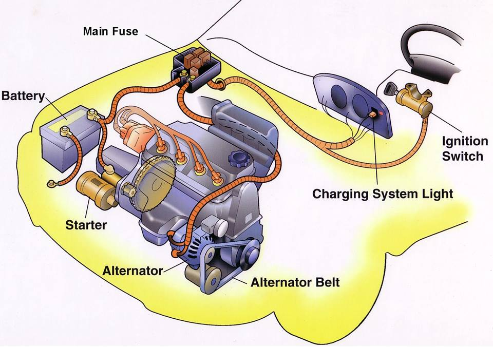
3. CHG Lights
CHG lamp or commonly also called “charging warning light” is an indicator light to indicate the present failure of the charging system. When the ignition key ON then this light will light up normally, as well as when the engine life of this lamp should turn on, if it is dead then it could mean the charging system failure.
4. Ignition key
The ignition key works as a switch. The charging system will be activated automatically when the engine is running, but to generate a magnetic field on the rotor coil must be done by a switch.
The ignition switch is used as a switch to connect and disconnect power (positive battery current) from battery to rotor coil. When the ignition key is ON, then the electricity from the battery to the coil rotor will be connected. However, when the ignition key is turned OFF then the power supply will be cut off. So it is not possible the alternator generates electricity when the ignition key is OFF even the engine crankshaft rotates.
5. Regulator
The function of the regulator is to regulate the voltage generated by the alternator. Why should it be there? because the voltage generated by the alternator depends on the engine’s RPM. This means that if the engine RPM is low, the alternator voltage is also low, but if the engine RPM is high then the alternator voltage is also high.
The regulator will be used to keep the voltage generated by the alternator not exceeding 14 volts even if the engine run in high RPM. This voltage setting aims to protect the electrical components of the vehicle to prevents over-voltage.
There are two types of regulators, namely type or conventional type and type of IC. The point type/conventional uses two coils to adjust the alternator output voltage. While the IC Regulator uses an IC circuit (Integrated Circuit) to regulate the output voltage.
6. Altenator
The function of the alternator is to convert a partial engine’s rotating energy into electricity. The alternator input comes from the engine pulley connected through a V belt, the rotation of the rotor will cause the intersection of the magnetic force line with the stator coil so that the electrons flow on the stator coil.
The electricity in the stator coil is not directly connected to the battery, but it must pass through the diode bridge to rectify the current. This is done because the current in the stator coil is AC (Alternate Current).
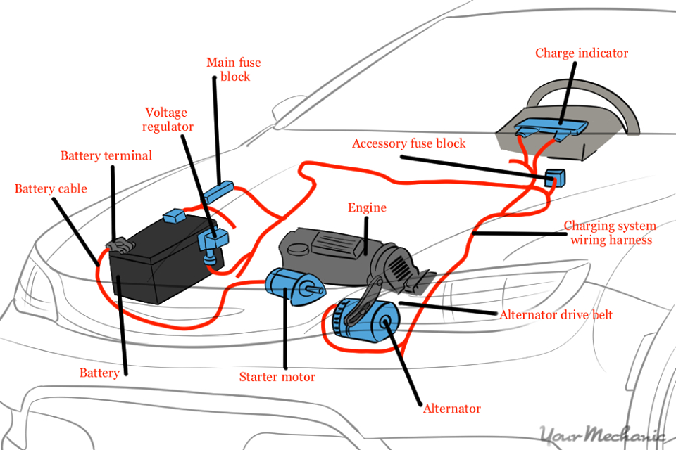
7. Charging Wire
The function of the charging wire is to connect every component of the charging system, there are at least two types of wires: standard wire and B + wire. The standard wire has a small diameter like the car’s electrical wiring in general, the function of this wire is connecting each terminal on the entire charging system.
While the B + wire has a larger diameter than the standard wire and almost matches the stater wire. The function of this wire is to connect the terminal B alternator with Battery.
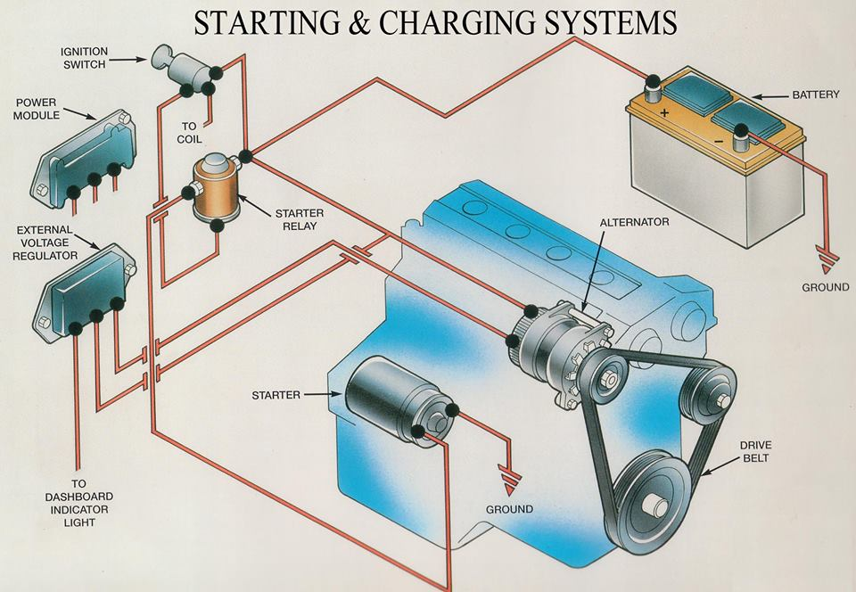
WORKING PRINCIPLE
The flow of electricity in the charging system
Electricity in each position of the ignition switch.
Ignition switch ACC or LOCK
Ignition switch ON (when the engine is not running)
When the ignition switch is in the ON position, current flows from the battery to the alternator. The reason for this is as follows. The alternator generally used for the vehicle generates electricity by rotating the magnet. The magnet is not the permanent magnet but the electromagnet that generates magnetic force by flowing electricity inside. Therefore, it is necessary to supply electricity to the alternator before starting the engine to prepare for generating electricity.
Ignition switch ON (when the engine is running)
FUNCTIONS OF ALTERNATOR
The alternator plays a major role in the charging system. The alternator has three functions of generating electricity, rectifying current and regulating voltage.
(1) Generation
Transmitting the engine revolution to the pulley via the v-ribbed belt turns the electromagnetic rotor, generating alternating current in the stator coil.
(2) Rectification
Since the electricity generated in the stator coil is alternating current, this cannot be used for the DC electric devices installed on the vehicle. To use the alternating current, the rectifier is used to rectify the alternating current into direct current.
(3) Regulation of voltage
IC regulator regulates the generated voltage to make the voltage constant even when the alternator speed or the amount of current flowing into the electric devices change.
CHARGING SYSTEM DIAGNOSIS
The following general information has been assembled as a guide for charging system diagnosis. Refer to the appropriate Original Equipment Manufacturer’s service manual for specific information pertaining to charging system diagnostic procedures and safety precautions for your vehicle.
BENCH TESTING
If an alternator test bench is available, follow the procedures found in the bench tester’s instruction manual to conduct an alternator performance test. This test will determine if the alternator output is within its performance specification, preventing unnecessary alternator replacement.
If the alternator output is within specification during bench testing, resolve problems in the remainder of the vehicle’s charging circuit and other electrical circuits that may affect charging circuit performance. Refer to the appropriate vehicle manufacturer’s service manual for the procedures and circuit schematics necessary to identify and correct additional charging circuit problems.
If the test bench results show the alternator’s output performance to be out of specification, replace the alternator. Follow the vehicle manufacturer’s recommended procedures to inspect the remainder of the charging circuit and other electrical circuits that may affect charging circuit performance.
NOTE: If the bench test identifies the regulator as defective, it may be possible to replace the regulator (internal or external) and return the alternator to service. If the regulator is replaced and the alternator returned to service, follow the vehicle manufacturer’s recommended procedures to inspect the remainder of the charging system and other electrical circuits that may affect charging circuit performance.
Whether or not a test bench was used to determine the condition of the alternator, the following Helpful Tips have been assembled to help isolate conditions that may affect charging circuit performance.
HELPFUL TIPS
1. What is the condition of the battery?
• A visual inspection and a performance test of the battery must always be performed before inspecting the charging system. The battery must be fully charged (12.6 volts) and the battery cables, terminals, and casein good, clean condition. This includes the frame and body grounds as well (refer to Battery Visual Inspection and Performance Testing).
2. Does a charge lamp, amperage (amp) gauge or voltmeter indicate a charging system problem?
Charge Lamp:
• Ignition ON engine not running – The charge lamp should illuminate.
• Ignition ON engine running – The charge lamp should illuminate briefly then turn OFF.
• Weak Battery – A weak battery can cause the charge lamp to illuminate during high amperage draw.
• Low Idle – A low idle can cause the charge lamp to illuminate dimly.
• Poor Wiring – Corroded, broken, loose or frayed wires/ connections could cause the charge lamp to illuminate during idle.
• Open Charge Lamp – Some charging systems will not properly operate if the charge lamp bulb fails.
Amp Gauge:
• Ignition ON engine not running – The amp gauge should read zero or slightly below.
• Ignition ON engine running – The amp meter should display a current output above zero. It will display a different level of charge depending on what electrical circuits are operating. A negative charge indicates the battery is discharging more quickly than the charging system can supply current.
• Wires and connectors – Corroded, broken, loose or frayed wires/connections could cause zero or erratic readings on the gauge.
Voltmeter:
• Ignition ON and engine not running – Gauge readings should be between 12.0 and 12.6 volts with the ignition ON and the engine not running. Readings below 12 volts could indicate insufficient charging, low battery, corroded, broken, loose or frayed wires/connections.
• Ignition ON and engine running – Gauge readings should be between 13.0 and 14.5 volts with the ignition ON and the engine running. A reading exceeding 14.5 volts could indicate a bad battery, failed regulator or poor wire connections. A reading below 13.2 volts could indicate a failed alternator or corroded, broken, loose or frayed wires/connections.
3. Are any fuses open?
• Check the fuses in all the fuse box(es). An open fuse indicates circuit problem(s) that may have an effect on the charging circuit. Check the owner’s manual or the manufacturer’s service manual for the location of each fuse box.
4. Is the fusible link(s) open?
• There may be several fusible links controlling battery voltage to the vehicle’s electrical circuits. If a fusible link is open, the supply voltage will be completely lost to all electrical systems or to the electric circuit(s) that the open fusible link controls. Check the owner’s manual or the manufacturer’s service manual for the location of each fusible link.
5. Is the alternator’s drive belt tension within specification?
• Too loose – If the drive belt is too loose, it will slip around the pulley causing the alternator to charge irregularly or not at all.
• Too tight – If the drive belt is too tight, internal bearing damage will cause premature alternator failure.
6. Are the alternator’s drive belt in good condition and the proper size?
• Worn or too narrow – If the alternator’s drive belt is worn or too narrow, it will slip around the pulley, causing the alternator to charge irregularly or not at all.
• New drive belt – The life of a new alternator drive belt is approximately 10 minutes. It is important to check and adjust the belt’s tension to the “used” specification after the initial 10 minutes of operation.
7. Has the vehicle been modified or additional equipment installed after it left the factory?
• Accessories – Non-factory accessories such as phones, computer outlets, televisions, refrigerators, stereo equipment or lights, among others, can overburden alternator performance and cause premature failure.
• Improper accessory installation – Improper accessory installation procedures can cause charging problems. Some of these problems may include poor ground points, loose connections or improper wiring.
8. Has any work been performed on the vehicle?
• Electrical ground points – Check the ground circuits between the battery and engine and also from the vehicle body to the frame for high resistance. Many times when a vehicle has been repaired, the ground point(s) are disturbed or not re-secured properly.
• Multiple electrical grounds – With multiple ground vehicles, each electrical circuit is assigned to one or more ground points. The poor ground at one ground point may cause feedback through another ground point causing unusual circuit activity.