¿Qué es un Inyector de combustible y cómo funciona?

Los inyectores son válvulas operadas eléctricamente (Es decir llevan un solenoide) que controlan con precisión la cantidad de combustible entregado haciendo une efecto de atomizado en la cámara de combustión. Al agregar el combustible al aire aspirado por el motor, se crea una mezcla con la relación combustible / aire requerida.

La mayoría de los sistemas de inyección electrónica de combustible (EFI) usan una ECU con controladores de circuito saturado de 12 voltios. Estos sistemas son muy económicos, simples y confiables. Este tipo de controlador funciona al suministrar 12 voltios a los inyectores y la ECU lo enciende y apaga para establecer un pulso de inyector de combustible. Los inyectores saturados son generalmente de mayor impedancia que el pico y la retención, funcionando en un rango de aproximadamente 10-16 ohmios.

La nueva tecnología utilizada en el diseño y la construcción de los inyectores de alta impedancia de hoy en día permite caudales mucho mayores, tiempos de respuesta mucho mejores y una operación de ancho de pulso bajo mucho más predecible que los diseños anteriores, todo sin sobrecalentamiento. Esto significa que los inyectores de baja impedancia ya no son el pico de rendimiento cuando se consideran los inyectores de combustible.

Funcionamiento

Una señal saturada es una señal simple utilizada para operar inyectores de alta impedancia. Se envía una señal de intensidad única a un inyector de combustible que hace que la válvula se abra y permanezca abierta hasta que la señal haya terminado. A diferencia del pico / retención, un inyector saturado permanece «encendido» durante todo el ancho del pulso. 

Esto significa que el flujo de corriente en el circuito del controlador y del inyector se mantiene bajo, lo que mantiene los componentes frescos durante una larga vida.Ventajade este diseño es el calor reducido. La desventaja de un controlador de circuito saturado es que tiene un tiempo de respuesta (tiempo de apertura y cierre) más lento que un tipo de pico y retención. 

Este tiempo más lento puede disminuir de alguna manera el rango de operación utilizable del inyector energizado por este controlador. 

Un inyector que funciona con un controlador de circuito saturado generalmente tiene un tiempo de reacción de 2ms, mientras que un controlador de pico y retención generalmente responde en 1,5ms . Otra desventaja de este diseño es que los inyectores saturados no pueden manejar grandes estilos CC o lb / hr debido a limitaciones en su velocidad.

Daños

  • Circuito abierto o cortocircuito a positivo o a tierra en cable (s);
  • No o mala conducción de la conexión del enchufe;
  • La conexión a tierra está suelta o corroída;
  • Mecánico culpa en componente.

Diagnóstico de Resistencia

  1. Asegúrese de que el encendido esté apagado y que el motor no arranque;
  2. Desconecte el conector del inyector de dos pines;
  3. Conecte un ohmímetro preciso entre los terminales del conector del inyector. La resistencia debe estar entre 10 y 16 ohmios;
  4. Enchufe el conector del inyector.

Señal del voltaje con Osciloscopio utilizando atenuador de corriente

Funcionamiento de la inyección de combustible DIESEL

La bomba de inyección es un componente importante del sistema de combustible del motor diésel y hay muchos componentes en el sistema de combustible del motor diésel. Un dispositivo que bombea combustible (diésel) y lo inyecta en la cámara de combustión del motor, con una presión muy alta y una sincronización realmente precisa. cantidad. El rendimiento del motor diésel está fuertemente influenciado por el sistema de inyección. Tradicionalmente, una bomba de inyección es accionada indirectamente desde el cigüeñal mediante engranajes, cadenas o correas dentadas (a menudo denominadas correas de distribución) que también accionan el árbol de levas de la bomba de inyección. Gira a la mitad de la velocidad del cigüeñal en un motor diésel convencional de cuatro tiempos. su sincronización es tal que el combustible se inyecta sólo muy ligeramente antes del punto muerto superior (punto muerto superior) de la carrera de compresión del cilindro.

La bomba de inyección convencional tiene dos tipos, como el tipo en línea y el tipo distribuidor. No importa qué tipo de producto sea, la parte más importante es la bomba. La bomba de inyección en línea utiliza una construcción en línea con disposición de émbolos, lo que significa que cada cilindro del motor recibe servicio de un émbolo, es por eso que este tipo se usa ampliamente en motores de gran potencia o vehículos pesados como autobuses y camiones. El tipo distribuidor utiliza un sistema de trabajo rotatorio, un émbolo funciona para inyectar combustible en todos los cilindros del motor. Este tipo se utiliza comúnmente en motores/vehículos ligeros y medianos.

  1. Bomba de inyección tipo en línea

A. Bombeo de combustible

Hay un árbol de levas en la imagen de arriba, impulsado por el motor a través de un engranaje temporizador que está conectado al cigüeñal. El árbol de levas gira a la misma velocidad que la velocidad del árbol de levas del motor; la velocidad del árbol de levas es la mitad de la velocidad del cigüeñal.

Luego hay empujadores con rodillos colocados sobre los lóbulos de las levas. El número de empujadores es igual al número de cilindros del motor. Empuja el émbolo encargado de bombear el combustible a la cámara de combustión. Por encima de cada empujador, se colocan resortes de retorno del émbolo para que los émbolos regresen al punto muerto inferior (punto muerto inferior) después de cada carrera.

El conjunto del émbolo consta de émbolo, cilindro, cara impulsora, orificio de alimentación y ranura de control (hélice). El émbolo se guía dentro del cilindro donde se presuriza el combustible, el émbolo tiene una ranura vertical y una ranura helicoidal que ayudan a variar la cantidad de combustible. La cara impulsora es impulsada por un manguito de control para regular la cantidad de combustible entregado a la unidad del inyector.

Antes de que el combustible bombeado a alta presión por el émbolo ingrese al inyector (boquilla), pasa primero por la válvula de entrega. La válvula de suministro sirve para mantener fija la presión del combustible en la manguera de inyección de combustible. Esto puede suceder porque el resorte de la válvula en el soporte de la válvula de entrega empujó el alivio cuando el émbolo dejó de bombear.

B. Ajustar la cantidad de combustible

Se ha explicado que el émbolo puede ajustar el combustible inyectado mediante el funcionamiento del manguito de control. ¿Cómo se puede mover la manga de control?

En el extremo delantero del árbol de levas de la bomba de inyección, hay un engranaje temporizador que actúa como impulsor inicial de los componentes de la bomba de inyección. En el otro extremo hay un dispositivo llamado Gobernador, sirve para ajustar la velocidad del motor de acuerdo a la carga de la máquina.

El gobernador funciona siguiendo la rotación que se produce en la máquina (a través del árbol de levas), si la rotación del motor es demasiado lenta, el gobernador empujará automáticamente la cremallera de control hacia adelante, esto hace que el émbolo entregue más combustible a la cámara de combustión. Y si la velocidad del motor es demasiado rápida, el gobernador empujará automáticamente la cremallera de control hacia atrás para reducir la distribución del combustible.

El gobernador empuja la cremallera de control y finalmente la cremallera de control mueve el émbolo por el manguito de control que conecta ambos.

  1. Bomba de inyección tipo distribuidor

A. Bombeo de combustible

El árbol de levas (eje de transmisión) gira el Camplate (Camdisk), que tiene una ranura/forma especial en la parte inferior. El camplate se asienta sobre el rodillo del temporizador para que pueda moverse hacia adelante y hacia atrás mientras gira. La placa giratoria mueve el émbolo para bombear y distribuir el combustible a todos los cilindros por turno.

Dentro del cilindro del émbolo (en conjunto con el émbolo, este conjunto se llama cabeza del rotor) hay varios orificios con el mismo número de cilindros de la máquina. Estos orificios sirven como líneas de distribución de combustible; al final de los orificios se encuentran las válvulas de suministro unidas a los soportes.

B. Ajuste de la cantidad de combustible

La cantidad de combustible que inyecta el émbolo está gobernada por un manguito de control (carrete de control) que es impulsado por un subconjunto de palanca del regulador. Para evitar el exceso de velocidad de la máquina, el manguito deslizante en el subconjunto del contrapeso empujará el regulador para reducir la distribución de combustible cuando el motor gira a alta velocidad.

Hay varias partes en el sistema de trabajo del gobernador:

  • Subconjunto de peso mosca
  • Manga deslizante
  • Palanca de tensión
  • Palanca de arranque
  • Manguito de control (carrete de control)
    *A partir de primavera
  • Gobernador de primavera
  • Resorte inactivo
  • Pasador de retención

FUEL SYSTEM: COMPONENTS, WORKING PRINCIPLES, SYMPTOMS AND EMISSION CONTROLS

No photo description available.

The function of the fuel system is to store and supply fuel to the cylinder chamber where it can be mixed with air, vaporized, and burned to produce energy. The fuel, which can be either gasoline or diesel is stored in a fuel tank. A fuel pump draws the fuel from the tank through fuel lines and delivers it through a fuel filter to either a carburetor or fuel injector, then delivered to the cylinder chamber for combustion.

COMPONENTS

1. Fuel Tank

The fuel tank is the main storage for the fuel that runs the vehicle. Generally speaking, the gas tank is generally found at, or under, the rear of the vehicle.

2. Fuel Injectors:

Sprays a fine mist of fuel into the combustion chamber of each cylinder or throttle body, depending on the design.
The fuel injectors are driven by the fuel pump and their job is to spray a fuel and air mixture into the combustion chamber, ready to be ignited to produce power to the driven wheels. The fuel injectors are basically a nozzle, with a valve attached, the nozzle creates a spray of fuel and air droplets (atomization). This can be viewed similar to that of a perfume dispenser or deodorant can in principle, spraying a fine mist.

3. Fuel Fill Hose

The Fuel Fill Hose is the main connector from the gas cap to the fuel tank. This is the point where the Gasoline (or other fuel) is put into the vehicle.

4. Gas Cap

The gas cap seals the fill hose and is used to ensure that

A) Gas does not spill out from the car, and 
B) that the fuel system remains pressurized correctly (in vehicles that use pressurized systems).

5. Fuel Pump

No photo description available.

The fuel pump is used to pump the fuel from the fuel tank, via the fuel lines into the fuel injectors, which spray the fuel into the combustion chamber- in order to create combustion. There are two types, mechanical fuel pumps (used in carburetors) and electronic fuel pumps (used in electronic fuel injection).

• Mechanical fuel pumps: these are driven normally by auxiliary belts or chains from the engine.
• Electronic fuel pumps: controlled by the electronic fuel injection system, these are normally more reliable and have fewer reliability issues than their mechanical counterparts.

6. Fuel Filter

No photo description available.

The fuel filter is the key to a properly functioning fuel delivery system. This is more true with fuel injection than with carbureted cars. Fuel injectors are more susceptible to damage from dirt because of their close tolerances, but also fuel injected cars use electric fuel pumps. When the filter clogs, the electric fuel pump works so hard to push past the filter, that it burns itself up. Most cars use two filters. One inside the gas tank and one in a line to the fuel injectors or carburetor. Unless some severe and unusual conditions occur to cause a large amount of dirt to enter the gas tank, it is only necessary to replace the filter in the line.

7. Fuel Lines

The Fuel Lines connect all of the various Fuel System components.
Steel lines and flexible hoses carry the fuel from the tank to the engine. When servicing or replacing the steel lines, copper or aluminum must never be used. Steel lines must be replaced with steel. When replacing flexible rubber hoses, the proper hose must be used. Ordinary rubber such as used in vacuum or water hose will soften and deteriorate. Be careful to route all hoses away from the exhaust system.

8. Fuel Gauge

The fuel gauge exists as a display item in the vehicle’s dashboard. It is intended to show to the driver the actual amount of fuel in the fuel tank. On older cars, it’s common for fuel gauges (or their related part, the sending unit) to be inaccurate. When you first start driving your classic car take time to learn how accurate the system is. It’ll save you from a long walk to the gas station if you run out of gas!

9. Fuel Gauge Sending Unit

In terms of the fuel system, this may be your biggest headache. Sending units, at best, are generally a flawed design. Generally, the sender is most accurate between 1/4 and 3/4 of a tank of gas. Outside of this, the gauge becomes progressively more inaccurate as you reach the tank limits (full or empty).

Based on the age of the vehicle, the type of carburetion/fuel injection, and the emissions standards in place at the time it may also have:

10. Fuel return lines

They are generally the same types of line tubing as the main Fuel Line. These specific lines are used for a couple purposes. Primarily they are used to return excess fuel to the gas tank for recirculation. Additionally, they capture gasoline vapors, which, as they are pushed back to the gas tank cool and condense back into the liquid. In particular, diesel-powered fuel injected engines often use the fuel as a cooling mechanism for the fuel injector. They can recirculate significant amounts of fuel.

11. Emission Vapor Controls

No photo description available.

These are often used in combination with fuel return lines. The goal of this section of the overall system is to ensure that gasoline vapors are not released into the ambient air. If this occurs a number of bad things may happen: 1) The earth-shattering kaboom of gasoline vapors igniting, 2) The unpleasant smell of gasoline is routed into the interior of the vehicle, and 3) It can harm the environment.

12. Fuel Pressure Regulator

Fuel Pressure Regulators are primarily found in fuel-injected cars. Fuel injection, as opposed to carburetion, is a high-pressure system. The fuel pressure regulator ensures that the system maintains the proper amount of pressurization.

13. Pulsation Damper:

As the fuel Injectors rapidly open and close in time with the engines OTTO cycle, pressure fluctuations appear in the fuel system. A Pulsation Damper job is to help combat the pressure levels reducing fuel delivery inconsistency.

WORKING PRINCIPLE

Image may contain: text

Some of this may seem a little silly, as many components are pretty obvious to all of us. Fundamentally, once you fill the tank with gasoline the system is «ready.» When you start the car the fuel pump begins the process of drawing fuel from the fuel tank, through the fuel lines and fuel filter, to the system that controls fuel/air delivery to the engine (a carburetor or fuel injector). While the car is running a continuous supply of fuel is delivered in this fashion.

The fuel system in modern cars is a complex and intricate combination of components and electronics. Generally, Fuel systems work in the following ways:

• Fuel is delivered from the fuel tank to the fuel injectors via a fuel pump and fuel lines. The pump is normally positioned close to the fuel tank or within the tank itself.
• Fuel leaving the fuel tank and fuel pump passes through a fuel filter which purifies and gets rid of any containment. This is normally a high capacity inline design, to maximize flow rates.
• Fuel travels along the fuel lines and is delivered to the fuel injectors. Fuel Injector pressures are controlled via a pressure regulator.
• Any fuel which is not used and exceeds pressure rates is returned via fuel lines back into the fuel tank.

Carbureted Engines

The fuel system for this type of engine is generally a low-pressure system. If the vehicle is equipped with a mechanical fuel pump, the number of revolutions of the motor (RPMs) control how quickly fuel is delivered. The faster the car is going (or revving) the greater the movement of the fuel pump and the overall volume of fuel being delivered. If the vehicle is equipped with an electric fuel pump the overall process is the same, but some form of the restrictor is necessary to ensure that the appropriate amount of fuel is delivered. This can be a pressure regulator, an overflow system with return lines, or a vehicle-specific mechanism.

Fuel Injected Engines

Once the vehicle is started, providing that the gas cap was installed and sealed correctly, the system becomes pressurized. Your modern car is probably fuel injected. Ever notice the release of air when you go to add gasoline? This is the vehicle releasing the system pressure. The electric fuel pump continuously pumps gasoline, ensuring that the system has the correct level of pressure. In addition to the normal fuel delivery, it also passes through the pressure regulator which ensures that the fuel pressure at the point of the Injector is correct so that the amount of fuel injected into the engine is appropriate. Depending on the year and the vehicle in question, the level of the technology that controls the system may be simple wiring type controls or a computer.

SYMPTOMS

The basic symptoms of any type of vehicle fuel system that is showing signs of wear or deterioration are:
• Difficult Engine Starting
• Slow or Hesitation at Acceleration
• Stalling While Driving
• Intermittent Power Loss
• Check Engine Light or Service Engine Soon Light Illuminated
• Engine Idling Rough
• Excessive Engine Smoke
• Noticeable Fuel Odors
• Decreased Fuel Economy

EMISSION CONTROLS

Emission controls are an add on to the basic fuel system and vary in complexity based on the year, vehicle, and legal controls in place at the time of manufacture. Fundamentally, they ensure that the appropriate amount of fuel is delivered, excess fuel is returned to the gas tank, and hazardous vapors are not allowed to escape the system. Because of the variability in this specific segment of the system, it is important for you to review the technical information that specifically relates to your vehicle.

INJECTION SYSTEM: COMPONENTS, TYPES AND WORKING PRINCIPLES

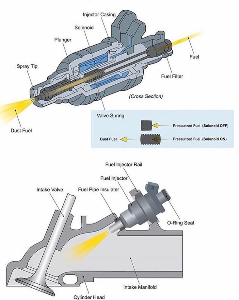
“ Fuel injector is an electronically controlled mechanical device that is responsible for spraying (injecting) the right amount of fuel into the engine so that a suitable air/fuel mixture is created for optimal combustion.”

The technology was created in the early 20th century and implemented on diesel engines first. By the final third of the 20th century, it had also become popular among regular gasoline engines.

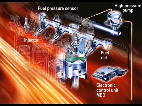
The electronic control unit (ECU at engine management system) determines the precise amount and specific timing of required gasoline (petrol) dose for every cycle, by collecting information from various engine sensors. So, the ECU sends a command electrical signal of the correct duration and timing to the fuel injector coil. In that way opens the injector and allows petrol to pass through it into the engine.

The one terminal of the injector coil is directly supplied by 12 volts which are controlled by the ECU, and the other terminal of the injector coil is open. When ECU determined the exact amount of fuel and when to inject it, activates the appropriate injector by switching the other terminal to the ground (mass, i.e. negative pole).

COMPONENTS

The objectives of the fuel injection system are to meter, atomize and distribute the fuel throughout the air mass in the cylinder. At the same time, it must maintain the required air-fuel ratio as per the load and speed demand on the engine.

* Pumping elements:

To move the fuel from the fuel tank to the cylinder.

* Metering elements:

To measure the supply of the fuel at the rate demanded by speed and load conditioning on the engine

* Metering control:

To adjust the rate of the metering elements for change in load and speed of the engine.

* Mixture control:

To adjust the ratio of the fuel and air as demanded by the load and speed.

* Distributing elements:

To divide the metered fuel equally among the cylinder.

* Timing control:

To fix the start and stop of the fuel-air mixing process.

TYPES OF FUEL INJECTORS

1. Top-Feed – Fuel enters from the in the top and exits the bottom.

2. Side-Feed – Fuel enters on the side on the injector fitting inside the fuel rail.

3. Throttle Body Injectors – (TBI) Located directly in the throttle body.

TYPES OF FUEL INJECTION SYSTEMS

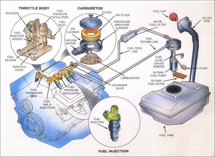
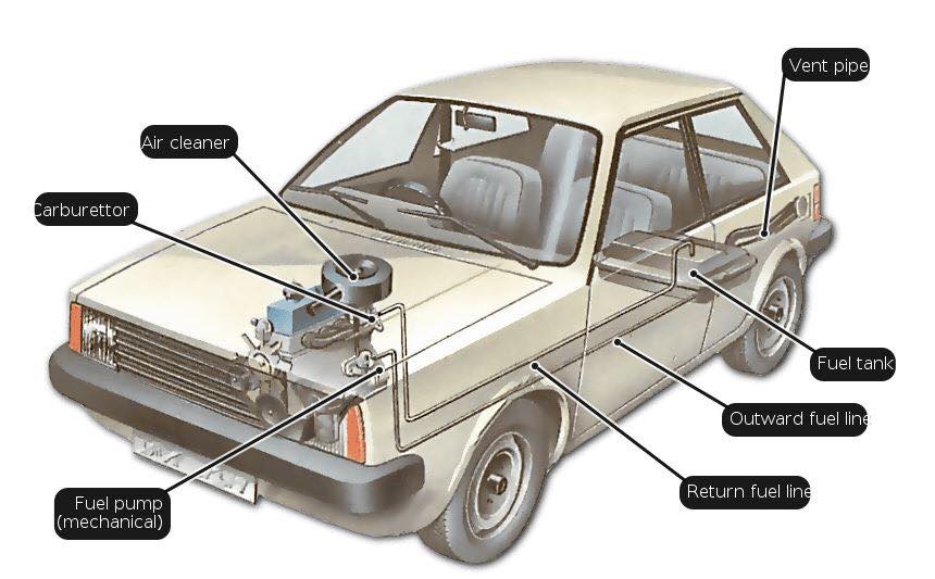
1. Single-Point OR Throttle Body Fuel Injection

Also referred to as a single port, this was the earliest type of fuel injection to hit the market. All vehicles have an air intake manifold where clean air first enters the engine. TBFI works by adding the correct amount of fuel to the air before it is distributed to the individual cylinders. The advantage of TBFI is that it’s inexpensive and easy to maintain. If you ever have an issue with your injector, you’ve only got one to replace. Additionally, since this injector has a fairly high flow rate, it’s not as easy to clog up.

Technically, throttle body systems are very robust and require less maintenance. That being said, throttle body injection is rarely used today. The vehicles that still use it are old enough that maintenance will be more of an issue than it would with a newer, lower mileage car.

Another disadvantage to TBFI is the fact that it’s inaccurate. If you let off the accelerator, there will still be a lot of fuel in the air mixture that is being sent to your cylinders. This can result in a slight lag before you decelerate, or in some vehicles, it can result in unburned fuel being sent out through the exhaust. This means that TBFI systems are not nearly as fuel efficient as modern systems.

2. Multiport Injection

Multiport injection simply moved the injectors further down towards the cylinders. Clean air enters the primary manifold and is directed out towards each cylinder. The injector is located at the end of this port, right before it’s sucked through the valve and into your cylinder.

The advantage of this system is that fuel is distributed more accurately, with each cylinder receiving its own spray of fuel. Each injector is smaller and more accurate, offering an improvement in fuel economy. The downside is that all injectors spray at the same time, while the cylinders fire one after the other. This means that you may have leftover fuel in between intake periods, or you may have a cylinder fire before the injector has had a chance to deliver additional fuel.

Multiport systems work great when you are traveling at a consistent speed. But when you are quickly accelerating or removing your foot from the throttle, this design reduces either fuel economy or performance.

3. Sequential Injection

Sequential fuel delivery systems are very similar to multiport systems. That being said, there is one key difference. Sequential fuel delivery is times. Instead of all injectors firing at the same time, they deliver fuel one after the other. The timing is matched to your cylinders, allowing the engine to mix the fuel right before the valve opens to suck it in. This design allows for improved fuel economy and performance.

Because fuel only remains in the port for a short amount of time, sequential injectors tend to last longer and remain cleaner than other systems. Because of these advantages, sequential systems are the most common type of fuel injection in vehicles today.

the one small downside to this platform is that it leaves less room for error. The fuel/air mixture is sucked into the cylinder only moments after the injector opens. If it is dirty, clogged, or unresponsive, your engine will be starved of fuel. Injectors need to be kept at their peak performance, or your vehicle will start to run rough.
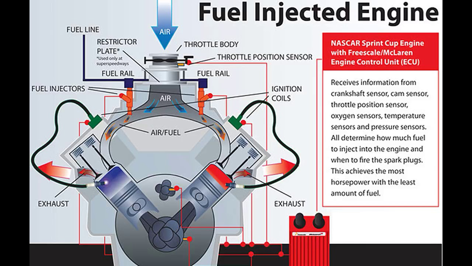
4. Direct Injection

If you’ve started to notice the pattern, you can probably guess what direct injection is. In this system, fuel is squirted right into the cylinder, bypassing the air intake altogether. Premium automobile manufacturers like Audi and BMW would have you believe that direct injection is the latest and greatest. With regards to the performance of gasoline vehicles, they’re absolutely right! But this technology is far from new. It’s been used in aircraft engines since the second world war, and diesel vehicles are almost all direct injection because the fuel is so much thicker and heavier.

In diesel engines, direct injection is very robust. Fuel delivery can take a lot of abuse, and maintenance issues are kept to a minimum.

With gasoline engines, direct injection is found almost exclusively in performance vehicles. Because these vehicles operate with very precise parameters, it’s especially important to maintain your fuel delivery system. Although the car will continue to run for a long time when neglected, the performance will quickly decline.

METHODS OF FUEL INJECTION

There are two methods of fuel injection in the compression ignition system

1. Air blast injection
2. Air less or solid injection

1. Air blast injection

This method was originally used in large stationary and marine engines. But now it is obsolete. In this method, the air is first compressed to very high pressure. A blast of this air is then injected carrying the fuel along with it into the cylinders. The rate of fuel injection is controlled by varying the pressure of the air. The high-pressure air requires a multi-stage compressor so as to keep the air bottles charged. The fuel ignites by the high temperature of the air caused by the high compression. The compressor consumes about 10% of the power developed by the engine, decreasing the net output of the engine.

2. Airless or solid injector

In this method, the fuel under high pressure is directly injected into the combustion chamber. It burns due to the heat of compression of the air. This method requires a fuel pump to deliver the fuel at high pressure around 300kg/cm^2. This method is used for all types of small and big diesel engines. It can be divided into two systems

1. Individual pump system: in this system each cylinder has its own individual high-pressure pump and a measuring unit.

2. Common rail system: in this system the fuel is pumped by a multi-cylinder pump into a common rail, the pressure in the rail is controlled by a relief valve. A measured quantity of fuel is supplied to each cylinder from the common rail.

This is all about the fuel injection system. If you have any query regarding this article, ask by commenting. If you like this article, don’t forget to share it on social networks. Subscribe our website for more informative articles. Thanks for reading it.
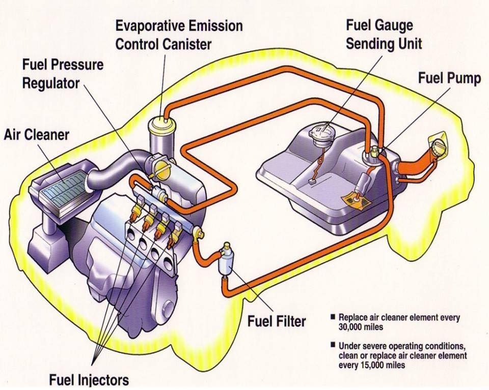
WORKING PRINCIPLES

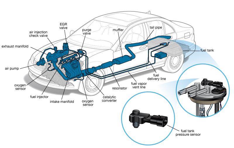
The injectors are controlled by the Engine Control Unit (ECU). First, the ECU obtains information about the engine conditions and requirements using different internal sensors. Once the state and requirements of the engine have been determined, the fuel is drawn from the fuel tank, transported through the fuel lines and then pressurized with fuel pumps. Proper pressure is checked by a fuel pressure regulator. In many cases, the fuel is also divided using a fuel rail in order to supply the different cylinders of the engine. Finally, the injectors are ordered to inject the necessary fuel for the combustion.

The exact fuel/air mixture required depends on the engine, the fuel used and the current requirements of the engine (power, fuel economy, exhaust emission levels, etc.)

(Automotive World)

Copyright © All rights reserved. | StoreCommerce by AF themes.
YouTube
YouTube
Instagram