Un freno de tambor es un freno que utiliza la fricción causada por un conjunto de zapatas o pastillas que presionan hacia afuera contra una parte giratoria con forma de cilindro llamada tambor de freno.
El término freno de tambor generalmente significa un sistema de frenado en el que las zapatas presionan la superficie interna del tambor. Cuando las zapatas presionan el exterior del tambor, generalmente se le llama freno de cierre. Cuando el tambor queda atrapado entre dos zapatas, de manera similar a un freno de disco convencional, a veces se le llama freno de tambor de pellizco, aunque estos frenos son relativamente raros. Un tipo relacionado llamado freno de banda utiliza una correa flexible o «banda» que envuelve el exterior de un tambor.
Los frenos de tambor se utilizan principalmente en el eje trasero de vehículos pequeños y compactos.
FUNCIÓN
Los frenos de tambor existen desde hace casi tanto tiempo como el propio automóvil y todavía se instalan hoy en día en una forma modificada y más sofisticada en los automóviles modernos. El término freno de tambor describe el principio de diseño: es decir, una estructura cilíndrica cerrada.
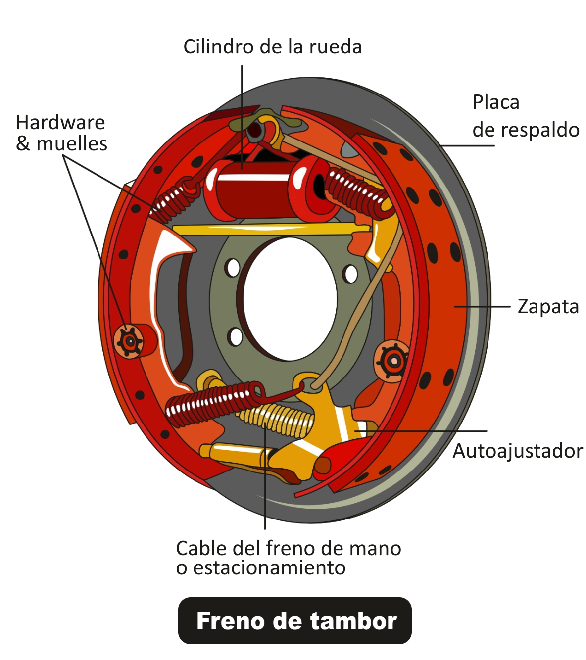
COMPONENTES DEL FRENO DE TAMBOR
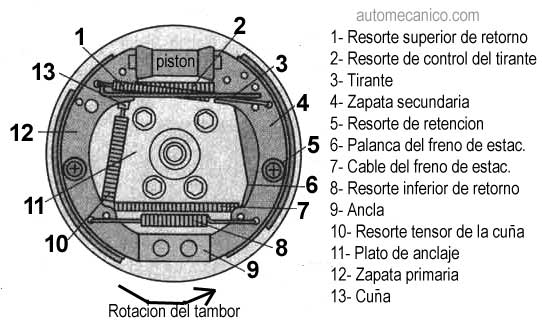
Un freno de tambor consta de los siguientes componentes:
- Placa de respaldo:
Proporciona una base sólida para otros componentes del freno de tambor unidos al manguito del eje.
cubo de anguila y gira con la rueda. A menudo está hecho de hierro fundido y es resistente al calor y al desgaste. Esto es lo que ves cuando miras un freno de tambor ensamblado y es el componente sobre el cual se aplica la fuerza de frenado para frenar o detener el automóvil.
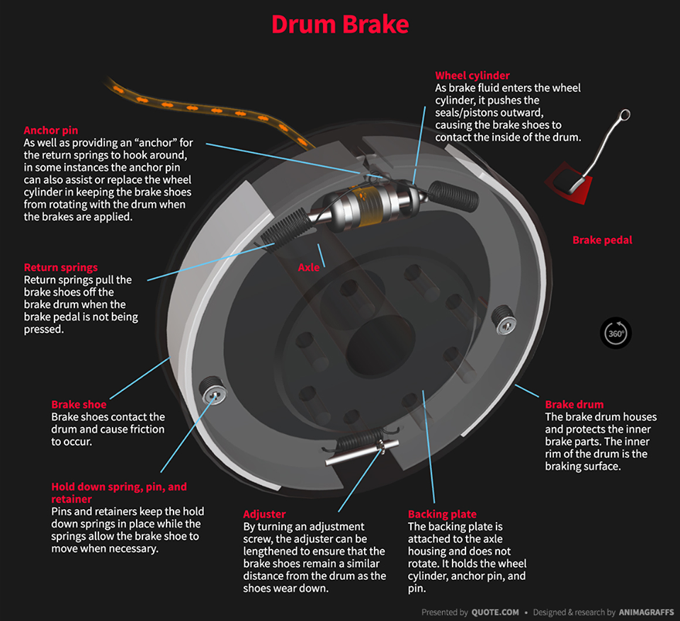
- Cilindro de rueda:
Contiene dos pistones, uno en cada extremo del cilindro, para accionar las zapatas de freno. El cilindro aplica presión a los pistones, lo que empuja las zapatas de freno hacia el tambor, desacelerando o deteniendo el automóvil. Se necesita un cilindro por rueda. - Zapata de freno:
Empuja el tambor para crear la fricción necesaria para frenar o detener el automóvil. Asegurado al respaldo, pero capaz de deslizarse cuando se aplica presión del cilindro de la rueda. Lleva adherido un revestimiento formado por compuestos orgánicos o metálicos. El revestimiento es lo que realmente entra en contacto con el tambor y se desgasta con el uso. Cada freno contiene dos zapatas. La zapata principal está más cerca de la parte delantera del vehículo, mientras que la zapata secundaria está más cerca de la parte trasera. Dependiendo del tipo y marca, las zapatas de freno pueden ser intercambiables. - Ajustador automático:
Mantiene las zapatas de freno a una distancia constante del tambor, incluso cuando el forro se desgasta. - Muelles de retorno:
Aleja las zapatas de freno del tambor cuando el conductor suelta el pedal del freno.
El tambor de freno está fijado a la rueda y gira con ella. Al frenar, el cilindro de la rueda separa las zapatas de freno fijas y las presiona contra el tambor de freno, ralentizándolo así. Cuando se suelta el freno, los resortes de retorno mueven las zapatas de freno a su posición original.
PRINCIPIO DE FUNCIONAMIENTO

Cuando el conductor pisa el pedal del freno, la potencia es amplificada por el servofreno (sistema servo) y convertida en presión hidráulica (presión de aceite) por el cilindro maestro. La presión llega a los frenos de las ruedas a través de un tubo lleno de aceite de frenos (líquido de frenos). La presión entregada empuja los pistones de los frenos de las cuatro ruedas. Los pistones presionan las pastillas de freno, que son materiales de fricción, contra las superficies interiores de los tambores de freno que giran con las ruedas. Los revestimientos se presionan sobre los tambores giratorios, que a su vez desaceleran las ruedas, desacelerando y deteniendo el vehículo.
TIPOS DE FRENOS DE TAMBOR
Hay principalmente tres tipos: frenos de tambor asistidos mecánicos, hidráulicos y neumáticos.
- Mecánico:
En el sistema de freno de tambor mecánico, como en los vehículos de dos ruedas y los rickshaw automáticos, las zapatas de freno son accionadas por una leva, que está unida al pedal y al varillaje del freno. Cuando presiona el pedal del freno, la leva gira. Por lo tanto, hace que las zapatas de freno se expandan hacia afuera y rocen contra el tambor.
La fricción entre las pastillas de freno y el tambor hace que el tambor deje de girar y, por tanto, la rueda se detenga. Cuando suelta el pedal del freno, los resortes retráctiles devuelven las zapatas de freno a su posición original. Esto da como resultado un espacio entre ellos y el tambor y nuevamente lo hace girar libremente.

- Hidráulico:
El sistema de freno de tambor hidráulico, como en los automóviles, es un poco superior al mecánico. En este diseño, el cilindro hidráulico de rueda reemplaza a la leva. En el sistema hidráulico, en lugar de una leva, los pistones del cilindro de la rueda empujan las zapatas de freno hacia afuera. Las zapatas de freno encajan en la placa de anclaje o placa de freno. Mantiene las piezas del sistema de frenos juntas y adheridas al eje del automóvil. Cuando presiona el pedal del freno, el aceite en el cilindro maestro del freno multiplica la fuerza hidráulica enviada a los cilindros de las ruedas. Por tanto, hace que sus pistones empujen hacia afuera. Los pistones, a su vez, hacen que las zapatas de freno se expandan y rocen contra el tambor. La fricción entre las pastillas de freno y el tambor hace que el tambor deje de girar y, por tanto, la rueda se detenga.
- Asistido neumático:
El tercer tipo: sistema de freno de tambor asistido neumático; Accionado por presión de aire, que funciona según el mismo principio que el sistema de freno de tambor mecánico. También es operado por una leva de mayor tamaño o leva en forma de ‘S’ y se conoce popularmente como sistema de frenos «S-Cam». Sin embargo, el aire comprimido a alta presión acciona un pistón neumático que hace girar la leva. La mayoría de los vehículos comerciales medianos y pesados utilizan este tipo de sistema de freno de tambor.
BASADO EN PRINCIPIO
- Freno de tambor tipo zapata delantera/posterior
«Zapato principal (o primario)» es un término que se refiere al zapato que se mueve en la dirección de rotación cuando se presiona contra el tambor. El otro zapato se llama “zapato final (secundario)”. La zapata principal se presiona en la misma dirección que la rotación de los tambores, y esta rotación ayuda a presionar las zapatas contra el tambor con mayor presión para obtener una fuerza de frenado más fuerte. Esto se llama efecto servo (efecto de autoimpulsión), que genera las potentes fuerzas de frenado de los frenos de tambor.
Estructuralmente, tiene un cilindro de rueda que alberga un pistón con el que se genera presión hidráulica para empujar las dos zapatas contra la superficie interior del tambor.
Las dos zapatas funcionan de tal manera que ambas se convierten en la zapata trasera o la zapata delantera dependiendo de si el vehículo avanza o retrocede. Los frenos de tambor generan una fuerza de frenado constante ya sea que el vehículo avance o retroceda. Esto se debe a que los frenos de tambor generan la misma fuerza de frenado en cualquier dirección. Generalmente, este tipo se utiliza para los frenos traseros de los turismos.
- Freno de tambor tipo zapata delantera gemela
Este tipo de freno de tambor tiene dos cilindros en las ruedas y dos zapatas principales. Cada cilindro de rueda presiona una zapata de modo que ambas zapatas actúan como delanteras cuando el vehículo avanza, proporcionando una fuerza de frenado superior.
Cada uno de los pistones alojados en los cilindros de las ruedas se desplaza en un sentido, por lo que cuando el vehículo va marcha atrás ambas zapatas actúan como traseras. Este tipo se utiliza principalmente para los frenos delanteros de camiones de tamaño pequeño y mediano.
El tipo de zapata delantera doble tiene pistones que se desplazan en ambas direcciones, lo que permite que ambas zapatas actúen como delanteras, independientemente de la dirección de desplazamiento. Este tipo se utiliza principalmente para los frenos traseros de camiones de tamaño pequeño y mediano.
- Freno de tambor tipo duo-servo
El tipo duo-servo presenta una estructura en la que dos zapatas de freno, llamadas zapata primaria y zapata secundaria, están unidas mediante un ajustador. La fuerte presión del efecto servo (efecto de autoimpulso) de la zapata primaria se transmite a la zapata secundaria vinculada, generando así una fuerza de frenado muy grande.
Este tipo se utiliza principalmente para los frenos de estacionamiento de los turismos, los frenos centrales de los camiones y los frenos de las carretillas elevadoras.
VENTAJAS Y DESVENTAJAS
Ventajas del sistema de freno de tambor:
- Diseño y piezas simples.
- Fácil y económico de fabricar
- Bajo costo de mantenimiento
- Vida comparativamente más larga
Desventajas del sistema de freno de tambor:
- Baja fuerza de frenado en comparación con los discos
- Los frenos se «desvanecen» cuando se aplican durante un tiempo prolongado
- Los forros de las zapatas de freno fabricados con amianto son perjudiciales para los seres humanos.
- En mojado, la adherencia al frenado se reduce considerablemente.
- Los revestimientos sin asbesto atrapan la humedad, lo que hace que los frenos de tambor se agarren repentinamente
SEGURIDAD
El tambor de freno es uno de los sistemas del vehículo más importantes en términos de seguridad. Tiene un desgaste relativamente bajo y una larga vida útil. Si se nota un deterioro en la capacidad de frenado de un freno de tambor, se debe consultar inmediatamente a un taller especializado. Los frenos de tambor sólo deben ser reemplazados por personal calificado. Al hacerlo, se deben observar las instrucciones de instalación del fabricante.