Funcionamiento de la inyección de combustible DIESEL

INLINE VS DISTRIBUTOR INJECTION PUMP

The Injection Pump is a major component of the diesel engine fuel system and there are many components on diesel engine fuel system A device that pumps fuel (diesel) and injects it into the engine combustion chamber, with very high-pressure and truly precise timing also quantity. The performance of diesel engine is heavily influenced by the injection system. Traditionally, an injection pump is driven indirectly from crankshaft by gears, chains or toothed belts (often referred to as a timing belt) that also drives the camshaft of injection pump.It rotates at half crankshaft speed in a convensional four stroke diesel engine. its timing is such that the fuel is injected only very slightly before top dead point (top dead centre) of the cylinder compression stroke.

Convensional Injection Pump has two kinds of type such as In Line type and Distributor type. No matter what kind of product it is, the most important part is the pump. In line injection pump use an in line construction on plunggers arrangement which mean each cylinder of the engine is served by one plunger, that’s why this type is widely used large-powered engines or heavy vehicles such as buses and trucks. Distrubutor type uses rotary works system, one plunger works to injects fuel into all cylinders of engine. This type is commonly used in light and medium engines / vehicles.

1. In Line Type Injection Pump

A. Pumping Fuel

There is Camshaft in a pictuure above, it driven by the engine via timer gear that connected to the crankshaft. The Camshaft rotates at the same speed as the engine camshaft speed, speed of camshaft is half of the crankshaft speed.

Then there is tappets with rollers sit over the cam lobes. The number of tappets equals the number of engine cylinders. It push the plunger in charge of pumping the fuel into the combustion chamber. Above each tappet, plunger return springs are placed to the plungers in returning to the bottom dead centre (bottom dead point) after each stroke.

Plunger asssmbly consists of Plunger, Barrel, Driving Face, Feed Hole and Control Groove (Helix). The plunger is guided inside the barrel where the fuel is pressurized, plunger has vertical groove and helical groove that assist in varying the fuel quantity, The driving face is driven by control sleeve in regulating the amount of fuel delivered to the injector unit.

Before the fuel that’s pumped at high pressure by the plunger entering the injector (nozzle), it passes the delivery valve first. The Delivery Valve serves to keep the fuel pressure in fuel injection hose fixed. Thit can happen because the valve spring in the delivery valve holder pushed the relief when the plunger stops pumping.

B. Adjusting the amount of fuel

It has been explained that the plunger can adjust the injected fuel by the works of control sleeve. How can the control sleeve move?

At the front end of the Injection pump camshaft, there is a timer gear as the initial driver of the components in the injection pump. At the other end there is a device called as Governor, serves to adjust the engine speed according to the load on the mchine.

Governor works following the rotation that occurs on the machine (via the camshaft),if the rotation of engine is too slow the govrnor will automatically push the control rack forward, this makes the plunger delivers more fuel to the combustion chamber. And if the engine speed is too fast the governor will automatically push the control rack backwards so that the fuel distribution becomes reduced.

The governor pushes the control rack and finally the control rack moves the plunger by the control sleeve that connects both.

2. Distributor type Injection Pump

A. Pumping Fuel

The camshaft (drive shaft) rotates The Camplate (Camdisk) which has special groove/shape on the bottom The camplate sits on the timer roller so it can move back and forth while rotating. The rotating camplate moves the plunger to pump and distribute the fuel to all cylinders in turn.

Inside the plunger barrel (into a set with the plunger, this set is called the rotor head) there are several holes with the same number of cylinders of the machine. These holes serve as the fuel distribution lines, at the end of the holes are the delivery valves attached in the holders.

B. Adjusting the Amount of Fuel

The fuel quantity that’s injected by the plunger, is governed by a control sleeve (control spool) which is driven by a governor lever sub assy. To avoid overrunning on the machine, the sliding sleeve on the flyweight sub assy will push the governor to reduce fuel distribution when the engine spins at high speed.

There are several parts on governor working system :
* Flyweight sub assy
* Sliding sleeve
* Tension lever
* Starting lever
* Control sleeve (control spool)
* Starting spring
* Governor spring
* Idle spring
* Retaining pin

Qué es el Aire acondicionado A/C y cómo funciona?

Image may contain: text

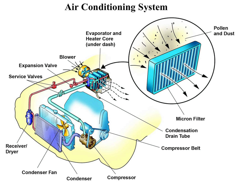
The automotive air conditioning system is also working on the reverse Brayton or Rankine cycle. As like all air conditioning system the aim of automotive air conditioning is to control the temperature and humidity of the atmospheric air and circulate the same in the automobile. The automotive air conditioning system consists of a refrigeration system, air circulation, and distribution system and a control system. The refrigeration system cools down the air which includes many other parts like compressor, condenser, etc. The air circulating system circulates this cooled air into the car which includes blower, air duct, etc. The controlling system used to control the temperature of the car by sensing it and control the refrigerating system.

Air conditioning has two main purposes:

No photo description available.

1. Cools the air entering the passenger compartment
2. Removes the moisture from the air so it feels more comfortable inside the vehicle.

Components of Car AC

Vehicles are found to have primarily three different types of air conditioning systems. While each of the three types differs, the concept and design are very similar to one another. The most common components which make up these automotive systems are the following:

The components used in automobile AC are-

1. Compressor –
It is also known as the heart of the AC system. The AC cycle starts with the compressor compressing the low-pressure gaseous refrigerant. The refrigerant leaves the compressor as a high-pressure gaseous refrigerant. The compressor is the central component of the AC system. A compressor provides pressure rise to the refrigerant to convert the vapor refrigerant into liquid refrigerant which in turn enables the further flow of the refrigerant through the condenser. The compressor of the car air conditioning system is driven by the crankshaft of the engine through the belt drive.

2. Condenser –
It is the device looks like a small radiator and is used after the compressor as it provides condensing i.e. lowers the temperature, of the high pressure and high-temperature liquid refrigerant sent by the compressor through forced convection provided either by radiator fan or by separated fan used with the condenser.
As hot compressed gasses are introduced into the top of the condenser, they are cooled off. As the gas cools, it condenses and exits the bottom of the condenser as a high-pressure liquid.

3. Expansion valve-
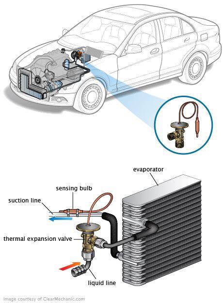
It is a device used in car air conditioning system to expand the high pressure, low-temperature liquid refrigerant sent by the condenser in order to release the pressure of the refrigerant before sending it to the evaporator for the further process.

Image may contain: text

4. Evaporator –
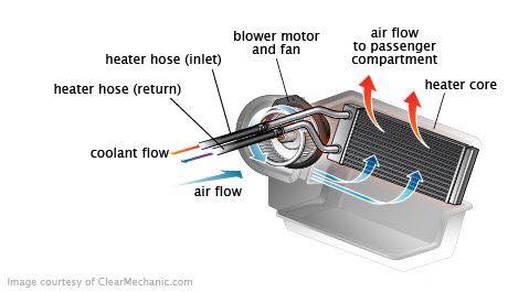
It is a device that looks like another heat exchanger and is placed just behind the AC vent over a dashboard of a car, an evaporator takes heat from the passenger’s compartment and convert the liquid refrigerant sent by the expansion valve into vapor, which in turn provides cooling through the fan inside a passenger’s cabin.

Its primary duty is to remove heat from the inside of your vehicle. A secondary benefit is dehumidification. As warmer air travels through the aluminum fins of the cooler evaporator coil, the moisture contained in the air condenses on its surface.

Note – Thermal expansion valve is used in vehicles that enable the passenger to change the temperature according to the requirement, by just adjusting the knob provided over a dashboard in passenger’s cabin.

5. Receiver-Dryer-
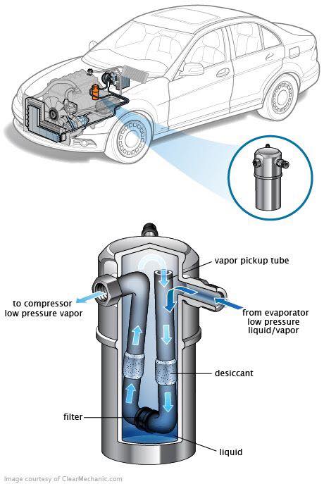
It is a safety catch used in an automobile or car air conditioning system as there is a chance that instead of vapors some liquid also flows towards the compressor which can damage the compressor, so the receiver dryer is used in between evaporator and compressor to convert that remaining liquid into vapors before sending it to compressor for compression.

Receiver/driers serve three very important functions:

No photo description available.

1. They act as temporary storage containers for oil and refrigerant when neither are needed for system operation (such as during periods of low cooling demand). This is the “receiver” function of the receiver/drier.

2. Most receiver/driers contain a filter that can trap debris that may be inside the A/C system.

3. Receiver/driers contain a material called desiccant. The desiccant is used to absorb moisture (water) that may have gotten inside the A/C system during manufacture, assembly or service. Moisture can get into the A/C components from humidity in the air. This is the “drier” function of the receiver/drier.

6. Refrigerant –
It is the heat-sensitive fluid with a very low boiling point that is used in AC as a medium of heat exchange.

7. Pressure Regulating Devices
Controlling the evaporator temperature can be accomplished by controlling refrigerant pressure and flow into the evaporator.

No photo description available.

8. Orifice Tube
The orifice tube, probably the most commonly used, can be found in most GM and Ford models. It is located in the inlet tube of the evaporator, or in the liquid line, somewhere between the outlet of the condenser and the inlet of the evaporator. This point can be found in a properly functioning system by locating the area between the outlet of the condenser and the inlet of the evaporator that suddenly makes the change from hot to cold.

9. Accumulator
Accumulators are used on systems that accommodate an orifice tube to meter refrigerants into the evaporator. It is connected directly to the evaporator outlet and stores excess liquid refrigerant. Introduction of liquid refrigerant into a compressor can do serious damage. Compressors are designed to compress gas not liquid. The chief role of the accumulator is to isolate the compressor from any damaging liquid refrigerant. Accumulators, like receiver-driers, also remove debris and moisture from a system.

No photo description available.

An accumulator is comparable in purpose to a receiver/drier. It serves similar, but slightly different functions. An accumulator is also a metal cylinder, but differs from a receiver/drier in these three ways:

1. An accumulator is considerably larger than a receiver/drier, usually around twice the volume.

2. The accumulator is connected to the evaporator outlet, in the low-pressure section of the system.

3. The accumulator’s primary function is to store liquid refrigerant that is exiting the evaporator, to prevent it from reaching the compressor. If liquid refrigerant were to enter the compressor, it could cause damage, as the compressor is not designed to pump liquid, only vapor.

Working of Car AC

The working of an automobile AC system is also almost the same as the normal AC but little difference is there-

1. The evaporator which is another heat exchanger used in AC takes heat from the passenger’s cabin which in turn converts the liquid refrigerant flowing through the evaporator into vapors which in turn provide cooling with the help of the blower fan.

2. This vapor having high-temperature low pressure is then sent to the compressor which in turn increases the pressure over the vapors and converts the vapor refrigerant into a liquid refrigerant. Now the refrigerant is in high pressure and high-temperature liquid state.

3. This high-pressure high-temperature liquid refrigerant is then sent to the condenser which lowers the temperature of this refrigerant by forced convection provided by the radiator fan or by separated fan used. Now the refrigerant is having a low temperature but the pressure of the liquid is almost the same.

4. This high pressure and the low-temperature refrigerant is then sent to expansion valve which in turn releases the pressure from the refrigerant and convert it into its original state.

Image may contain: text

5. This refrigerant is then again sent to the evaporator for the further cycle.

Note – Between evaporator and compressor a receiver dryer is used that converts the remaining liquid refrigerant from the evaporator into the vapors before sending it to the compressor.

• Receiver dryer also provides filtering of the system by absorbing the contaminated foreign materials inside the AC system.

Copyright © All rights reserved. | StoreCommerce by AF themes.
YouTube
YouTube
Instagram