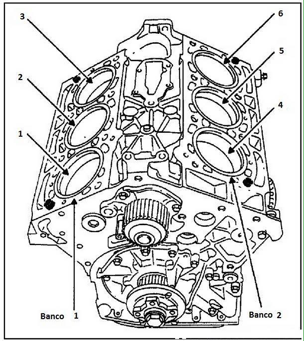
Bastantes diagnósticos en el motor hacen referencia a errores en sensores que pertenecen a algún banco, en la mayor parte de los casos encontramos banco 1 y banco 2 (BANK1 ,BANK2), esto descripción del banco nos permite localizar el dispositivo o sensor que presente fallas o lecturas incorrectas cuando exista mas de dos dispositivos iguales instalados en el motor.
Es importante tener identificado cual es el Banco 1 o el banco 2 en caso de motores V6 en adelante, ya que si en un diagnóstico con el escaner nos llegará a marcar por ejemplo «Circuito Calefactor de Sensor de Oxigeno HO2 S1 B2 nos hace referencia que es el sensor 2 después del catalizador ubicado en el banco número dos, por lo general si miramos de frente el motor es el que está de lado izquierdo y si llamamos de frente nos referimos a donde están las poleas , ya que de lado derecho el primero cilindro el que está mas acercado al frente es el banco 1 , en motor L3, L4, L5 Lineales sólo es un sólo banco por lo que nos va a decir Banco 1 Sensor 2 por ejemplo
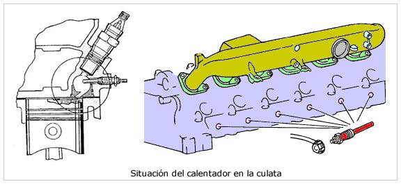
Precalentadores La comprobación y sustitución de las bujías de incandescencia (calentadores) en los motores Diesel (también llamadas «bujías de precalentamiento») es una operación muy sencilla que podemos realizar nosotros mismos, la única dificultad que podemos encontrar es la que supone la ubicación de las bujías en el motor, que en ocasiones se encuentran en lugares de difícil acceso.
El procedimiento a seguir para la comprobación y sustitución de las bujías de incandescencia es el siguiente:
Desconectar el borne negativo de la batería por seguridad para evitar cortocircuitos. Desconectar los cables que van a cada uno de los calentadores, para ello aflojar el tornillo pequeño que sujeta el terminal del cable al calentador. Podemos comprobar que los calentadores funcionan correctamente sin desenroscarlos de la culata, para ello utilizaremos un multimetro. Una vez quitado los cables limpiar bien alrededor de los calentadores (donde van roscados a la culata) para que no penetre suciedad dentro del motor una vez quitado el calentador. Después echar un poco de aflojatodo (aceite) para que penetre un poco en la rosca y sea mas fácil desenroscar el calentador. Ahora viene la parte mas delicada, para ello tienes que usar una llave fija, acodada o una llave para bujías que se ajuste a la tuerca labrada en el calentador, desenroscar el calentador como si fuera un tornillo es decir aflojando hacia la izquierda. Cada vez que quitas un calentador inmediatamente colocas el nuevo para que no entre suciedad dentro del motor. Por ultimo vuelves a colocar todos los terminales eléctricos (cableado) en los calentadores.
Las bujías de incandescencia o calentadores pueden ir conectados eléctricamente en «serie» o en «paralelo», aunque actualmente y desde hace años se usa mas la conexión paralelo de forma que una bujía averiada no afecta al funcionamiento de las demas.
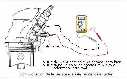
Método para comprobar que los calentadores funcionan correctamente sin desmontarlos de la culata Nos puede ocurrir que el vehículo presente dificultades a la hora de arrancarlo (ponerlo en marcha) esto puede ser debido a que «uno» de los calentadores este mal, en este caso el vehículo arrancara con dificultades. Si son «dos» los calentadores que están mal, entonces será casi imposible arrancar el vehículo, dependerá principalmente de la temperatura ambiente. Para comprobar si tenemos un calentador mal, sin desmontarlo de la culata procederemos de la siguiente manera:
Desconectamos el contacto con la llave de arranque del vehículo. Desconectamos los terminales eléctricos de cada una de las bujías de incandescencia que queremos comprobar. Con el multimetro seleccionado en la escala de ohmios, colocamos el terminal positivo (cable rojo) en la bujía de incandescencia en su conexión eléctrica. El terminal negativo (cable negro) lo colocamos tocando la culata (sobre metal para hacer masa). El multimetro nos tiene que dar como resultado un valor muy bajo de 1 a 3 ohmios, depende del fabricante (por ejemplo: las bujías de incandescencia que lleva el Renault Megane 1.9D de la marca Bosch, tienen una resistencia interna de 1,3 ohmios). Con este valor de resistencia sabemos que esta se encuentra en buenas condiciones. Una bujía de incandescencia en mal estado nos dará un valor de resistencia muy alto, esto quiere decir que la bobina interna de la bujía de incandescencia esta cortada.}
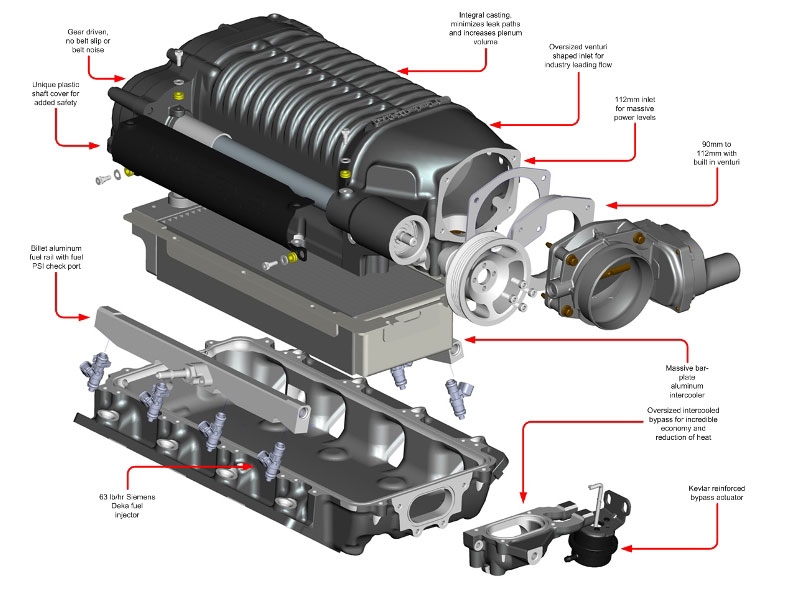
Los sobrealimentadores son básicamente compresores/sopladores que toman aire a presión ambiental normal, lo comprimen y lo empujan con fuerza hacia el motor. La potencia al compresor/soplador se transmite desde el motor a través de la transmisión por correa.
La adición de una cantidad adicional de mezcla de aire y combustible al cilindro aumenta la presión media efectiva del motor. Un incremento en MEP hace que el motor produzca más potencia. De esta forma, añadir un compresor al motor lo hace más eficiente.
TIPOS DE SOBRECARGADOR
Existen principalmente dos tipos de sobrealimentadores. El primero se conoce como sobrealimentador de desplazamiento positivo y el otro se conoce como sobrealimentador dinámico. La diferencia básica entre ambos es que el sobrealimentador de desplazamiento positivo mantiene un nivel constante de presión en todas las velocidades del motor, mientras que el sobrealimentador dinámico proporciona una presión cada vez mayor a medida que aumenta la velocidad. Esta es la diferencia fundamental básica entre ellos. Estos supercargadores se subdividen como se indica a continuación.
SOBRECARGADOR DE DESPLAZAMIENTO POSITIVO:
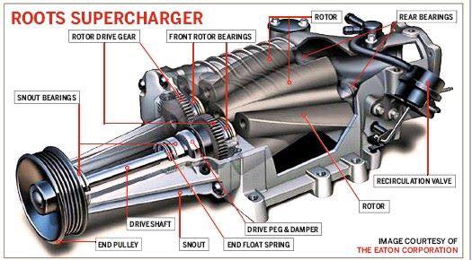
Como comentamos en la sección anterior, estos supercargadores entregan el mismo volumen de carga a cualquier velocidad del motor o estos supercargadores no dependen de la velocidad del motor. Los principales tipos de sobrealimentadores de desplazamiento positivo son los de raíz y los de doble tornillo.
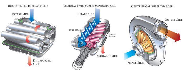
Estilo raíz Este diseño tiene dos rotores especialmente diseñados que giran en direcciones opuestas (uno en el sentido de las agujas del reloj y el otro en el sentido contrario a las agujas del reloj) para comprimir el aire. Según el diseño del rotor, este sobrealimentador se subdivide en dos tipos: rotor de dos lóbulos, rotor de tres lóbulos, rotor de cuatro lóbulos, etc. A medida que el rotor gira, atrapan el aire mediante estos lóbulos que vienen del lado de succión o del puerto de entrada y lo fuerzan hacia la descarga. puerto lateral o de salida. La cantidad de aire comprimido es independiente de la velocidad del motor y cada vez este sobrealimentador comprime la misma cantidad de aire.
Ventajas:
Diseño sencillo
Más adecuado con motor de alta velocidad
Desventajas:
Flujo de aire pulsante a baja velocidad.
Menos eficiencia.
Pesado.
Crean mucho calor debido a la fricción.
Fuga trasera a baja velocidad.
Proporcione la misma cantidad de aire a RPM bajas y altas.
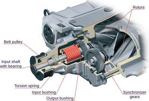
Sobrealimentador de doble tornillo
Como su nombre lo indica, este tipo de sobrealimentador tiene dos tornillos que giran en diferentes direcciones. Uno de los tornillos gira en el sentido de las agujas del reloj y el otro en el sentido contrario a las agujas del reloj. El funcionamiento de este sobrealimentador es el mismo que el del tipo raíz. También aspira aire de un lado y lo entrega al puerto de salida. Este dispositivo proporciona un flujo de aire más suave en comparación con el estilo raíz.
Ventajas:
No hay problema de fuga trasera.
Proporcionar un flujo de aire más suave.
Desventajas:
Alta generación de calor debido a la fricción.
Ruidoso en funcionamiento.
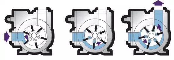
Sobrealimentador tipo paleta
Varias paletas están montadas en el tambor del sobrealimentador. Estas paletas se empujan hacia afuera mediante resortes precomprimidos. Esta disposición ayuda a que la paleta permanezca en contacto con la superficie interior del cuerpo. Ahora, debido a la rotación excéntrica, el espacio entre dos paletas es mayor en la entrada y menor en la salida. De esta forma, la cantidad de aire que entra por la entrada disminuye su volumen en su camino hacia la salida. Una disminución del volumen da como resultado un aumento de la presión del aire. Así, la mezcla obtenida a la salida está a mayor presión que a la entrada.
SOBRECARGADOR DINÁMICO:
Como comentamos anteriormente, este tipo de sobrealimentador aumenta la presión del aire a medida que aumenta la velocidad del motor. El efecto de sobrealimentación en este tipo depende en gran medida de la velocidad del motor. También se subdividió en los siguientes tipos.
Tipo centrífugo
Como su nombre lo indica, este tipo utiliza fuerza centrífuga para comprimir el aire. El diseño de este sobrealimentador es el mismo que el del compresor centrífugo. Tiene un impulsor que está conectado con el cigüeñal mediante una transmisión por correa. Cuando el motor gira, hace girar el impulsor que aspira el aire de un lado. Sobre este aire actúa la acción centrífuga que aumenta su energía cinética y la entrega a un difusor. El aire que entra en la difusión tiene alta velocidad a baja presión. El difusor convierte este aire de baja presión y alta velocidad en aire a alta presión y baja velocidad. Este aire a alta presión luego se envía al motor.
Ventajas: Es de tamaño pequeño. Alta eficiencia.
Desventajas: La cantidad de aire no es fija.
Onda de presión
flujo axial
MÉTODOS DE SOBRECARGACIÓN
Hay otras formas de forzar el aire que no necesitan potencia adicional a diferencia de los compresores. Los 2 más utilizados son:
Sobrealimentación por efecto Ram En este caso, el colector de admisión está diseñado de tal manera que el aire ingresa automáticamente al cilindro. ¡El aire intenta entrar continuamente en el cilindro pero las válvulas de admisión se abren y cierran varias veces por segundo! Cada vez que la válvula se cierra, el aire simplemente choca contra ella. Esto genera una onda de presión que viaja en la dirección opuesta hasta que golpea el pleno y se refleja.
Ahora bien, si la frecuencia de resonancia del pleno y del motor coincide, esta onda de presión transporta más aire al cilindro haciendo el trabajo de un sobrealimentador.
Sobrealimentación bajo pistón – Este tipo de método se adopta generalmente en grandes motores marinos. Utiliza la parte inferior del pistón para comprimir el aire. Con la sincronización adecuada de las válvulas, este sistema proporciona un suministro adecuado de aire comprimido, ya que hay 2 carreras de suministro por cada carrera de succión de cada carrera.
VENTAJAS Y DESVENTAJAS DEL SUPERCARGADOR
Ventajas de la sobrealimentación
Mayor potencia de salida
Mayor inducción de masa de carga.
Mejor atomización del combustible
Mejor mezcla de combustible y aire.
Mejores productos de eliminación
Mejores características de par en todo el rango
Aceleración rápida del vehículo.
Combustión completa y suave
Incluso se puede utilizar combustible con mala calidad de ignición.
Arranque en frío mejorado
Reducción del humo de escape
Reducción del consumo específico de combustible.
Mayor eficiencia mecánica.
Funcionamiento suave y reducción de la tendencia a la detonación del diésel.
Desventajas de la sobrealimentación
Mayor tendencia a la detonación en motores SI.
Aumento del estrés térmico
Mayor pérdida de calor debido al aumento de la turbulencia.
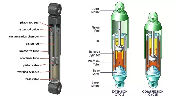
Los amortiguadores son básicamente bombas de aceite. Un pistón está fijado al extremo del vástago del pistón y actúa contra el fluido hidráulico en el tubo de presión. A medida que la suspensión sube y baja, el fluido hidráulico pasa a través de pequeños orificios, llamados orificios, dentro del pistón. Sin embargo, estos orificios sólo dejan pasar una pequeña cantidad de líquido a través del pistón. Esto desacelera el pistón, lo que a su vez desacelera el movimiento del resorte y la suspensión.
Todos los amortiguadores modernos son dispositivos de amortiguación hidráulica sensibles a la velocidad, lo que significa que cuanto más rápido se mueve la suspensión, más resistencia proporciona el amortiguador.
Gracias a esta característica, los amortiguadores se ajustan a las condiciones de la carretera. Como resultado, los amortiguadores reducen la tasa de:
Rebotar
Rodar o balancearse
Zambullida con freno y sentadilla con aceleración
Los amortiguadores funcionan según el principio de desplazamiento de fluido tanto en el ciclo de compresión como en el de extensión. Un automóvil o camioneta típico tendrá más resistencia durante su ciclo de extensión que durante su ciclo de compresión. El ciclo de compresión controla el movimiento del peso no suspendido de un vehículo, mientras que la extensión controla el peso suspendido más pesado.
FUNCIONES DEL AMORTIGUADOR
La función principal del amortiguador es absorber los impactos y amortiguarlos lo antes posible para que se pueda obtener una conducción suave.
Algunas otras funciones importantes del amortiguador son Limita el movimiento de la carrocería del vehículo. Estabiliza nuestro viaje como se mencionó anteriormente. Estabiliza los neumáticos del vehículo que se alteran debido a un impacto repentino, por lo que también es muy importante por motivos de seguridad. También minimiza el desgaste de los neumáticos y la carrocería del automóvil y, por lo tanto, reduce el costo general de mantenimiento. Puede parecer un trabajo sencillo, pero esto es lo principal de lo que depende el nivel de comodidad de su viaje.
PRINCIPIO DE FUNCIONAMIENTO
Para entender el amortiguador, es muy importante entender su funcionamiento.
En primer lugar debemos saber que generalmente existen dos tipos de amortiguadores uno es hidráulico y otro es neumático. Sin embargo, el funcionamiento de ambos tipos de amortiguadores es el mismo.
Un amortiguador generalmente está acoplado a un resorte, que convierte ondas de choque repentinas en movimiento oscilatorio. Este movimiento oscilatorio nos brinda un alivio instantáneo del impacto, pero nadie puede recorrer todo el recorrido con estas oscilaciones.
Aquí surge la necesidad de un amortiguador, que se utiliza para amortiguar las oscilaciones que producen los resortes. Un amortiguador general contiene un pistón perforado en una cámara hidráulica. La cámara está totalmente sellada por lo que si el pistón tiene que hacer algún movimiento la única manera es dejar pasar el líquido hidráulico a través de él.
Cuando se produce un choque, el pistón tiene que moverse debido al choque. Cuando el pistón se mueve, el líquido hidráulico del amortiguador tiene que pasar a través de él.
Cuando el líquido pasa a través de los diminutos orificios perforados del pistón, el pistón tiene que trabajar un poco contra él. Ese trabajo se realiza a expensas de la energía generada debido al choque y, por lo tanto, pronto el amortiguador pierde toda la energía del choque, lo que resulta en una marcha suave y sin oscilaciones.
TIPOS DE DISEÑO DE AMORTIGUADORES
Actualmente se utilizan varios diseños de amortiguadores:
Diseños de doble tubo
Gas cargado
PSD (amortiguación sensible a la posición)
ASD (amortiguación sensible a la aceleración)
Monotubo
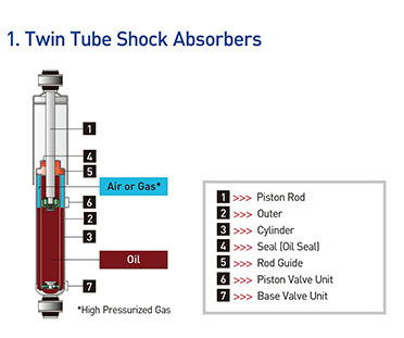
A. Tubo doble: diseño cargado con gas
La función principal de la carga de gas es minimizar la aireación del fluido hidráulico. La presión del gas nitrógeno comprime las burbujas de aire en el fluido hidráulico. Esto evita que el aceite y el aire se mezclen y formen espuma. La espuma afecta el rendimiento porque se puede comprimir, pero el fluido no. Con la aireación reducida, el amortiguador puede reaccionar más rápido y de manera más predecible, lo que permite un tiempo de respuesta más rápido y ayuda a mantener el neumático firmemente plantado en la superficie de la carretera.
Ventajas:
Mejora el manejo al reducir el balanceo, el balanceo y la caída.
Reduce la aireación y ofrece un mayor rango de control sobre una variedad más amplia de condiciones de la carretera en comparación con las unidades sin gasolina.
Menor desvanecimiento: los amortiguadores pueden perder capacidad de amortiguación a medida que se calientan durante el uso. Los amortiguadores cargados con gas podrían reducir esta pérdida de rendimiento, llamada desvanecimiento
B. Tubo doble – Diseño PSD
Los ingenieros de conducción tuvieron que hacer concesiones entre válvulas suaves y válvulas firmes. Con válvulas suaves, el fluido fluye más fácilmente. El resultado es una marcha más suave, pero con un manejo deficiente y mucho balanceo. Cuando la válvula es firme, el fluido fluye con menos facilidad. Se ha mejorado el manejo, pero la marcha puede volverse dura. Con la llegada de la carga de gas, los ingenieros de viajes pudieron abrir los controles de orificio de estas válvulas y mejorar el equilibrio entre la comodidad y las capacidades de control disponibles en los amortiguadores tradicionales sensibles a la velocidad. Un salto más allá del control de la velocidad del fluido es una tecnología avanzada que tiene en cuenta la posición de la válvula dentro del tubo de presión. Esto se llama amortiguación sensible a la posición (PSD). La clave de esta innovación son las ranuras cónicas de precisión en el tubo de presión. Cada aplicación se ajusta individualmente, adaptando la longitud, profundidad y conicidad de estas ranuras para garantizar una comodidad de marcha óptima y mayor control. En esencia, esto crea dos zonas dentro del tubo de presión. La primera zona, la zona de confort, es donde se realiza la conducción normal. La segunda zona, la zona de control, se utiliza durante situaciones de conducción exigentes.
Ventajas:
Permite a los ingenieros de conducción ir más allá de la simple válvula sensible a la velocidad y utilizar la posición del pistón para ajustar la característica de conducción.
Se ajusta más rápidamente a las condiciones cambiantes de la carretera y del peso que los amortiguadores estándar
Dos amortiguadores en uno: comodidad y control
C. Tubo doble: diseño ASD (réflex)
Un nuevo giro en el compromiso comodidad/control es una tecnología innovadora que proporciona un mayor control para el manejo al tiempo que mejora la comodidad de marcha llamada Amortiguación Sensible a la Aceleración (ASD). Esta tecnología va más allá de la amortiguación tradicional sensible a la velocidad para enfocar y abordar el impacto. Este enfoque en el impacto se logra mediante la utilización de un nuevo diseño de válvula de compresión. Esta válvula de compresión es un sistema mecánico de circuito cerrado que abre un bypass para que el fluido fluya alrededor de la válvula de compresión.
Ventajas:
Se mejora el control sin sacrificar la comodidad del conductor
La válvula se ajusta automáticamente a los cambios en las condiciones de la carretera
Reduce la dureza de la marcha
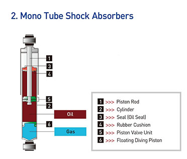
Diseño monotubo (tipos estándar)
Se trata de amortiguadores de gas a alta presión con un solo tubo, el tubo de presión. Dentro del tubo de presión hay dos pistones: un pistón divisor y un pistón de trabajo. El pistón y la varilla de trabajo son muy similares al diseño del amortiguador de doble tubo. La diferencia en la aplicación real es que un amortiguador monotubo se puede montar boca abajo o boca arriba y funcionará de cualquier manera. Además de su flexibilidad de montaje, los amortiguadores monotubo son un componente importante, junto con el resorte, para soportar el peso del vehículo. Otra diferencia que puedes notar es que el amortiguador monotubo no tiene válvula de base. En cambio, todo el control durante la compresión y extensión se realiza en el pistón. Durante la operación, el pistón divisor se mueve hacia arriba y hacia abajo a medida que el vástago del pistón entra y sale del amortiguador, manteniendo el tubo de presión lleno en todo momento.
Ventajas:
Puede montarse boca abajo, lo que reduce el peso no suspendido
Puede funcionar a menor temperatura ya que el tubo de trabajo está expuesto al aire
Equipo original en muchos vehículos de pasajeros, SUV y camionetas livianas nacionales importados y de alto rendimiento.
ELECTRIC VEHICLES: COMPONENTS AND WORKING PRINCIPLE
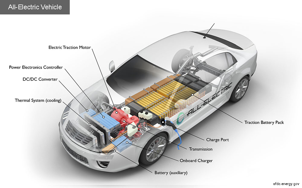
All-electric vehicles (EVs) have an electric motor instead of an internal combustion engine. The vehicle uses a large traction battery pack to power the electric motor and must be plugged into a charging station or wall outlet to charge. Because it runs on electricity, the vehicle emits no exhaust from a tailpipe and does not contain the typical liquid fuel components, such as a fuel pump, fuel line, or fuel tank.
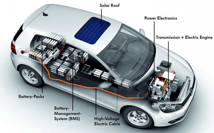
All-electric vehicles (EVs) use a battery pack to store the electrical energy that powers the motor. EVs are sometimes referred to as battery electric vehicles (BEVs). EV batteries are charged by plugging the vehicle into an electric power source. Although electricity production may contribute to air pollution, the U.S. Environmental Protection Agency categorizes all-electric vehicles as zero-emission vehicles because they produce no direct exhaust or emissions.
Both heavy-duty and light-duty EVs are commercially available. EVs are typically more expensive than similar conventional and hybrid vehicles, although some cost can be recovered through fuel savings, a federal tax credit, or state incentives.
Components of an All-Electric Car
Battery (all-electric auxiliary): In an electric drive vehicle, the auxiliary battery provides electricity to power vehicle accessories.
Charge port: The charge port allows the vehicle to connect to an external power supply in order to charge the traction battery pack.
DC/DC converter: This device converts higher-voltage DC power from the traction battery pack to the lower-voltage DC power needed to run vehicle accessories and recharge the auxiliary battery.
Electric traction motor: Using power from the traction battery pack, this motor drives the vehicle’s wheels. Some vehicles use motor generators that perform both the drive and regeneration functions.
Onboard charger: Takes the incoming AC electricity supplied via the charge port and converts it to DC power for charging the traction battery. It monitors battery characteristics such as voltage, current, temperature, and state of charge while charging the pack.
Power electronics controller: This unit manages the flow of electrical energy delivered by the traction battery, controlling the speed of the electric traction motor and the torque it produces.
Thermal system (cooling): This system maintains a proper operating temperature range of the engine, electric motor, power electronics, and other components.
Traction battery pack: Stores electricity for use by the electric traction motor.
Transmission (electric): The transmission transfers mechanical power from the electric traction motor to drive the wheels.
Driving Range Today’s EVs generally have a shorter range (per charge) than comparable conventional vehicles have (per tank of gas). The efficiency and driving range of EVs vary substantially based on driving conditions. Extreme outside temperatures tend to reduce range because more energy must be used to heat or cool the cabin. High driving speeds reduce range because of the energy required to overcome increased drag. Compared with gradual acceleration, rapid acceleration reduces range. Hauling heavy loads or driving up significant inclines also reduces range.
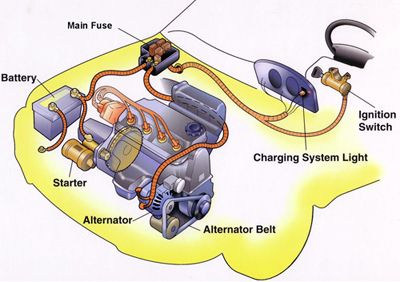
The starter motor is an electric motor that rotates your engine in order to allow the spark and fuel injection systems to begin the engine’s operation under its own power. Typically, the starter is a large electric motor and stator coil mounted to the bottom (generally to one side) of the vehicle’s transmission bell housing where it connects to the engine itself. The starter has gears which mesh with a large flywheel gear on the back side of the engine, which turns the central crankshaft. Because this is a lot of physical weight and friction to overcome, starter motors are generally powerful, high-speed motors and use an ignition coil to ramp up their power before engaging.
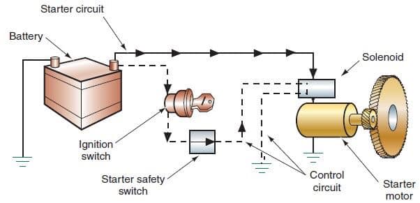
Components of the starting system
1. Battery
The automotive battery, also known as a lead-acid storage battery, is an electrochemical device that produces voltage and delivers current. In an automotive battery, we can reverse the electrochemical action, thereby recharging the battery, which will then give us many years of service. The purpose of the battery is to supply current to the starter motor, provide current to the ignition system while cranking, to supply additional current when the demand is higher than the alternator can supply and act as an electrical reservoir.
2. Ignition Switch
The ignition switch allows the driver to distribute electrical current to where it is needed. There are generally 5 key switch positions that are used:
1. Lock- All circuits are open ( no current supplied) and the steering wheel is in the lock position. In some cars, the transmission lever cannot be moved in this position. If the steering wheel is applying pressure to the locking mechanism, the key might be hard to turn. If you do experience this type of condition, try moving the steering wheel to remove the pressure as you turn the key. 2. Off- All circuits are open, but the steering wheel can be turned and the key cannot be extracted. 3. Run- All circuits, except the starter circuit, are closed (current is allowed to pass through). Current is supplied to all but the starter circuit. 4. Start- Power is supplied to the ignition circuit and the starter motor only. That is why the radio stops playing in the start position. This position of the ignition switch is spring loaded so that the starter is not engaged while the engine is running. This position is used momentarily, just to activate the starter. 5. Accessory- Power is supplied to all but the ignition and starter circuit. This allows you to play the radio, work the power windows, etc. while the engine is not running.
Most ignition switches are mounted on the steering column. Some switches are actually two separate parts;
* The lock into which you insert the key. This component also contains the mechanism to lock the steering wheel and shifter. * The switch which contains the actual electrical circuits. It is usually mounted on top of the steering column just behind the dash and is connected to the lock by a linkage or rod.
3. Neutral Safety Switch
This switch opens (denies current to) the starter circuit when the transmission is in any gear but Neutral or Park on automatic transmissions. This switch is normally connected to the transmission linkage or directly on the transmission. Most cars utilize this same switch to apply current to the backup lights when the transmission is put in reverse. Standard transmission cars will connect this switch to the clutch pedal so that the starter will not engage unless the clutch pedal is depressed. If you find that you have to move the shifter away from park or neutral to get the car to start, it usually means that this switch needs adjustment. If your car has an automatic parking brake release, the neutral safety switch will control that function also.
4. Starter Relay
A relay is a device that allows a small amount of electrical current to control a large amount of current. An automobile starter uses a large amount of current (250+ amps) to start an engine. If we were to allow that much current to go through the ignition switch, we would not only need a very large switch, but all the wires would have to be the size of battery cables (not very practical). A starter relay is installed in series between the battery and the starter. Some cars use a starter solenoid to accomplish the same purpose of allowing a small amount of current from the ignition switch to control a high current flow from the battery to the starter. The starter solenoid in some cases also mechanically engages the starter gear with the engine.
5. Battery Cables
Battery cables are large diameter, the multistranded wire which carries the high current (250+ amps) necessary to operate the starter motor. Some have a smaller wire soldered to the terminal which is used to either operate a smaller device or to provide an additional ground. When the smaller cable burns, this indicates a high resistance in the heavy cable. Care must be taken to keep the battery cable ends (terminals) clean and tight. Battery cables can be replaced with ones that are slightly larger but never smaller.
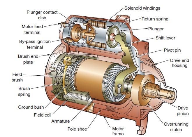
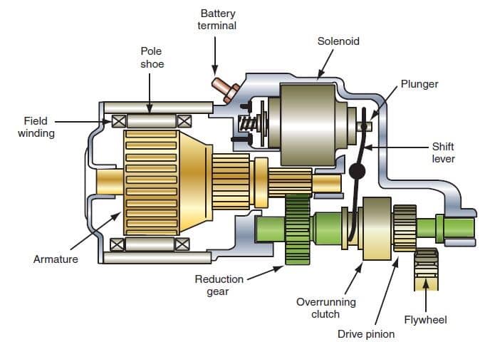
6. Starter Motor
The starter motor is a powerful electric motor, with a small gear (pinion) attached to the end. When activated, the gear has meshed with a larger gear (ring), which is attached to the engine. The starter motor then spins the engine over so that the piston can draw in a fuel/ air mixture, which is then ignited to start the engine. When the engine starts to spin faster than the starter, a device called an overrunning clutch (Bendix drive) automatically disengages the starter gear from the engine gear.
Working principles.
To make an engine start it must be turned at some speed, so that it sucks fuel and air into the cylinders, and compresses it.
The powerful electric starter motor does the turning. Its shaft carries a small pinion (gear wheel) which engages with a large gear ring around the rim of the engine flywheel.
In a front-engine layout, the starter is mounted low down near the back of the engine.
The starter needs a heavy electric current, which it draws through thick wires from the battery. No ordinary hand-operated switch could switch it on: it needs a large switch to handle the high current.
The switch has to be turned on and off very quickly to avoid dangerous, damaging sparking. So a solenoid is used – an arrangement where a small switch turns on an electromagnet to complete the circuit.
The starter switch is usually worked by the ignition key. Turn the key beyond the ‘ignition on’ position to feed current to the solenoid.
The ignition switch has a return spring so that as soon as you release the key it springs back and turns the starter switch off.
When the switch feeds current to the solenoid, the electromagnet attracts an iron rod.
The movement of the rod closes two heavy contacts, completing the circuit from the battery to the starter.
The rod also has a return spring -when the ignition switch stops feeding current to the solenoid, the contacts open and the starter motor stops.
The return springs are needed because the starter motor must not turn more than it has to in order to start the engine. The reason is partly that the starter uses a lot of electricity, which quickly runs down the battery.
Also, if the engine starts and the starter motor stays engaged, the engine will spin the starter so fast that it may be badly damaged.
The starter motor itself has a device, called a Bendix gear, which engages its pinion gear with the gear ring on the flywheel only while the starter is turning the engine. It disengages as soon as the engine picks up speed, and there are two ways by which it does so – the inertia system and the pre-engaged system.
The inertia starter relies on the inertia of the pinion gear – that is, its reluctance to begin to turn.
The pinion gear is not fixed rigidly to the motor shaft – it is threaded on to it, like a freely turning nut on a very coarse-thread bolt.
Imagine that you suddenly spin the bolt: the inertia of the nut keeps it from turning at once, so it shifts along the thread of the bolt.
When an inertia starter spins, the pinion moves along the thread of the motor shaft and engages with the flywheel gear ring.
It then reaches a stop at the end of the thread, begins to turn with the shaft and so turns the engine.
Once the engine starts, it spins the pinion faster than its own starter-motor shaft. The spinning action screws the pinion back down its thread and out of engagement.
The pinion returns so violently that there has to be a strong spring on the shaft to cushion its impact.
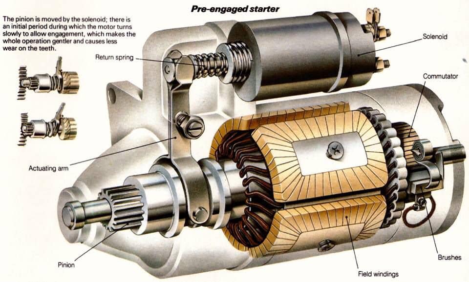
The violent engagement and disengagement of an inertia starter can cause heavy wear on the gear teeth. To overcome that problem the pre-engaged starter was introduced, which has a solenoid mounted on the motor.
There’s more to a car starter system: As well as switching on the motor, the solenoid also slides the pinion along the shaft to engage it.
The shaft has straight splines rather than a Bendix thread so that the pinion always turns with it.
The pinion gear is brought into contact with the toothed ring on the flywheel by a sliding fork. The fork is moved by a solenoid, which has two sets of contacts that close one after the other.
The first contact supplies a low current to the motor so that it turns slowly – just far enough to let the pinion teeth engage. Then the second contacts close, feeding the motor a high current to turn the engine.
The starter motor is saved from over-speeding when the engine starts by means of a freewheel clutch, like the freewheel of a bicycle. The return spring of the solenoid withdraws the pinion gear from engagement.
FOUR WHEEL STEERING SYSTEM: FUNCTIONS, REQUIREMENTS, MODES OF OPERATION AND APPLICATION
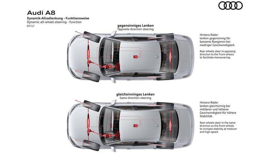
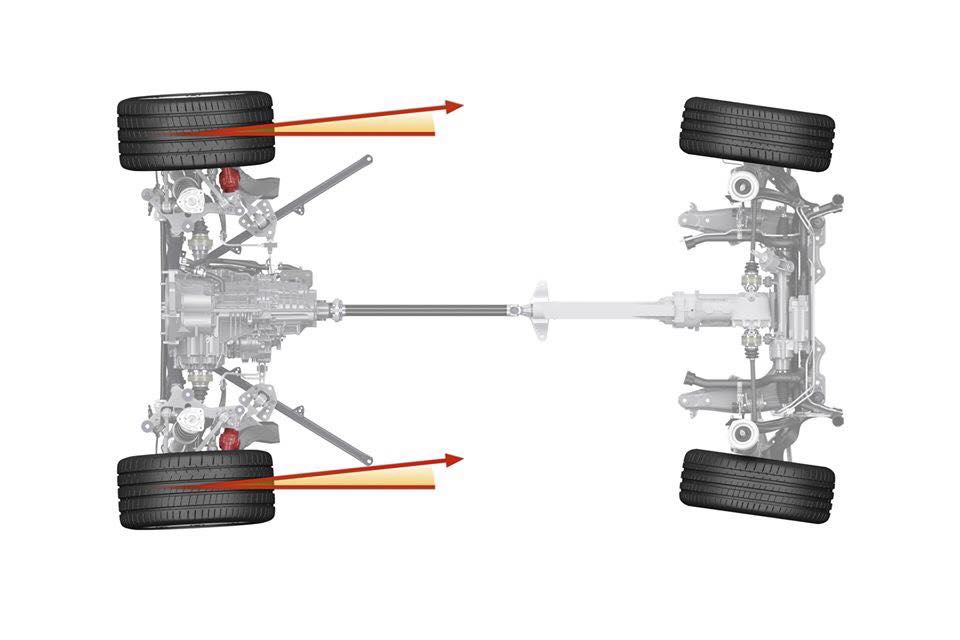
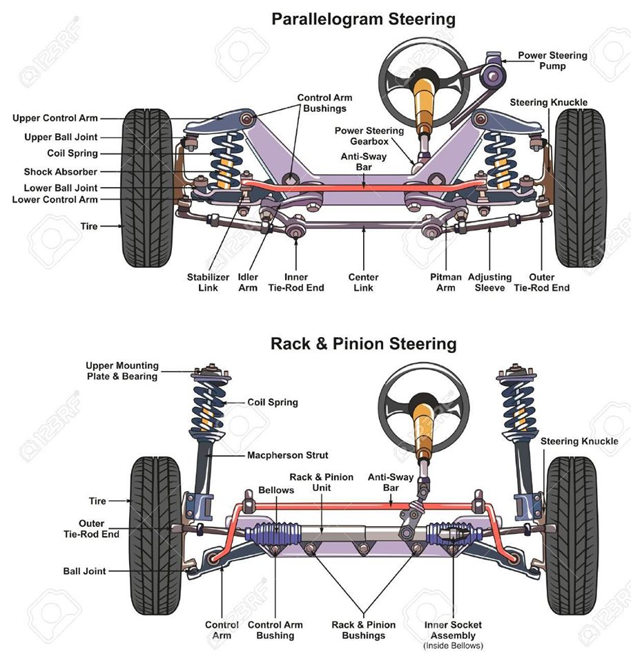
Four-wheel steering, 4WS, also called rear-wheel steering or all-wheel steering, provides a means to actively steer the rear wheels during turning maneuvers. A system that uses all four wheels to steer the car. The steering angle is usually limited to 2° or 3°. Turning the rear wheels in the opposite direction to the front at slow speeds can allow faster maneuvering and a much tighter turning radius. Turning the rear wheels in the same direction as those at the front at high speed allows sudden lane changes with much greater stability. Turning the rear wheels in the same direction as the front when parking makes parallel parking much easier. Four-wheel steering is a relatively new technology that improves maneuverability in cars, trucks and trailers.
FUNCTIONS
• To provide directional stability of vehicle • To facilitate straight ahead recovery • To minimize tire wear • To absorb major parts of the road shocks • To provide perfect rolling motions of the road wheels
REQUIREMENTS
The steering system has the following requirements:
• The steering system must be able to turn the front wheels sharply yet easily and smoothly. • The steering should be made lighter at low speeds and heavier at high speeds. • Smooth recovery while the vehicle is turning. • Minimum transmission of shock from road surface.
MODES OF 4WS
1. Two Wheel Steer: A 4-Wheel Steering System is flexible enough to work as a 2-wheel steer by restricting the rear wheel movement.
2. Four Wheel Steer/ Slow Speeds: Front wheel directions are opposite to rear wheel directions. This helps to take sharp turn with least turning radius. At slow speeds, the rear wheels turn in the direction opposite to the front wheels. It can reduce the turning circle radius by 25%, and can be equally effective in congested city conditions, where U-turns and tight streets are made easier to navigate.
3. Crab Steer Mode/ High Speeds: At high speed lane change, both the front and rear wheels face in same direction. In high speeds, turning the rear wheels through an angle opposite to front wheels might lead to vehicle instability and is thus unsuitable. Hence, at speeds above 80 kmph, the rear wheels are turned in the same direction of front wheels in four-wheel steering systems.
4. Zero turn: Front and Rear wheels are so aligned that the vehicle moves in a circle of ‘’zero radius’’.
APPLICATIONS
• Parking: During a parking a vehicles driver typically turns the steering wheels through a large angle to achieve a small tuning radius. By counter phase steering of the rear wheels, 4ws system realizes a smaller turning radius then is possible with 2ws system. As a result, vehicle is turned in small radius at parking.
• Junctions: On a cross roads or other junction where roads intersect at 900 degrees or tighter angles, counter phase steering of the rear wheels causes the front and rear wheels to follow more or-less path. As a result, the vehicle can be turned easily at a junction.
• Slippery road surfaces: During steering operation on low friction surfaces, steering of the rear wheels suppress sideways drift of the vehicle’s rear end. As a result, the vehicles direction is easier to control.
• High-speed straight-line operation: When traveling in a straight line at high speed, a vehicle’s driver frequently needs to make small steering correction to maintain the desired direction, in phase steering of the rear wheels minimizes these corrective steering inputs.
• Narrow roads: On narrow roads with tight bends, counter-phase steering of the rear wheels minimizes the vehicle’s turning radius, thereby reducing side-to –side rotation of the steering wheels and making the vehicle easier to turn.
ADVANTAGES
• Car more efficient and stable on cornering. • Improved steering responsiveness and precision. • High-speed straight-line stability. • Notable improvement in rapid, easier, safer lane changing maneuvers. • Smaller turning radius and tight space maneuverability at low speed. • Relative Wheel Angles and their Control. • Risk of hitting an obstacle is greatly reduced
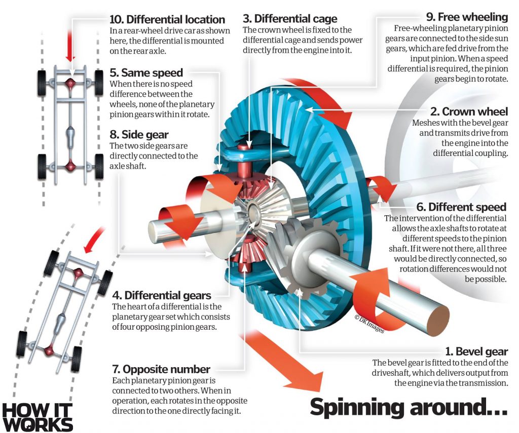
DIFFERENTIAL: FUNCTIONS, WORKING PRINCIPLES AND CLASSIFICATION
Differential is a very important part in a vehicle, as a component transfer the engine power is transmitted to the wheels. Engine power is transferred by a rear propeller shaft to wheel first changed direction by differential rotation are then referred to rear axle shafts after that to the rear wheels.
Differential functions to reduce the speed received by the propeller shaft to produce a great moment and to change the direction of rotation of the propeller shaft 900 is transmitted to wheel next round through the rear axle shaft rear separately. However, if the differential is not working then it will result in the vehicle which cannot be run A.
HOW IT WORKS?
At the time of straight road.
During the vehicle runs straight, the wheels of the rear axle will be screened by the drive pinion through the ring gear differential case, wheel-wheel differential gear pinion shaft, wheel-pinion differential gears, side gear teeth is not spinning, remain to be drawn into the ring gear rotation. Thus the spin on the wheel left and right alike.
At the time of turning.
At the time of vehicle turning left prisoners left wheel is bigger than the right wheel. If the differential case with the ring gear rotates the pinion will rotate on its axis and also the movement around the left side gear, so round the right hand side gear increases, the side where the number of revolutions of the gear which is 2 times round the ring gear. It can be said that the average second round gear is comparable with the rotary ring gear. as it should.
WORKING PRINCIPLE OF DIFFERENTIAL
The basic principle of the differential gear unit can be understood by using equipment that consists of two gears pinion and rack. Both rack can be moved in the vertical direction as far as the weight rack and slip resistance will be lifted simultaneously. Placed between the tooth pinion rack and pinion gear connected to the braces and can be moved by these braces. When the same load “W” placed on each rack then braces (Shackle) is pulled up the second rack would be lifted at the same distance, this will prevent the pinion gear does not rotate. But if a greater burden placed on the left rack and pinion buffer will then be drawn up along the gear rack rotates the load gets heavier, which is attributed to differences in prisoners who are given the pinion gear, so the smaller the burden will be lifted. The raised rack spacing is proportional to the number of turns pinion gear. In other words that rack gets custody larger still and while prisoners who received a smaller load will move. This principle is used in the planning of differential gears.
FUNCTIONS OF DIFFERENTIAL
1. Further reduces the rotations coming from the gear box before the same are passed on to the rear axles. 2. Changes the direction of axis of rotation of the power by 90o i.e. from being longitudinal to transverse direction. 3. To distribute power equally to both the rear driving axles when the tractor is moving in straight ahead direction. 4. To distribute the power as per requirement to the driving axles during turning i.e. more rotations are required by the outer wheel as compared to the inner wheel – during turns.
Open differentials are the most basic form of a differential. The purpose is to allow for different speeds between the two wheels, while torque split is held constant at 50/50. A common misconception with open differentials is that when one wheel is lifted, 100 per cent of the torque is sent to it. This is not true, however the amount of torque sent to the wheel with traction is very low because the amount of torque required to spin a wheel is also low. Remember, both wheels always receive equal torque, but if one has no resistance (eg. if it’s in the air), the amount of torque sent to the drive axle as a result is very low. • Splits the engine torque into two outputs • Allows the wheels to rotate at different speeds • When one tire loses traction, the opposing tire will also lose power • Found in family sedans and economy cars
Advantages: • Allows for completely different wheel speeds on the same axle, meaning no wheel slip will occur while going around a corner, as the outside tyre will travel further. • From an efficiency standpoint, less energy will be lost through the differential versus alternative options. • Cost.
Disadvantages: • When one wheel has poor traction, this drastically limits the amount of power the vehicle can put down. Because the torque distribution is always 50/50, if one wheel cannot put down much power, the other will receive an equally low amount of torque.
2. Locked Differential (Including Locking And Welded Diffs)
Locked differentials are on the opposite side of the spectrum versus open diffs. The purpose is for wheel speed to remain constant between the two wheels, and the major benefit here is that torque will go to the wheel with traction, up to 100 per cent at a single wheel. For off-road use, it is common for the differential to have a locking feature, so that it is open when driving on pavement. • Connected wheels always spin at the same speed • Turning the vehicle can be very difficult • Found in Jeep Wranglers and most full-size trucks
Advantages: • Allows for torque to go to the wheel with the most traction. For all differential styles, this will allow for the most torque to reach the ground on any surface condition. • For off-road use where tyre wear is not an issue, this is about as good as it gets. Robust, simple, and very effective. • In situations where it’s desirable to keep wheel speed constant on an axle (ex: drifting), this is an easy solution (a welded differential works exactly the same).
Disadvantages: • A locked differential will not allow for wheel speed differences between the right and left wheels. This means additional tyre wear, as well as binding within the drivetrain as a result.
3. Viscous Limited-Slip Differential (VLSD)
VLSD are fairly simple as far as operation, however they have some drawbacks in comparison to other forms of LSDs. • Combination of open and locking differentials • Usually acts as an open differential • Automatically locks when slipping occurs • Found in sports vehicles like Nissan 370Z and the Mazda MX-5 Miata
Advantages: • Allows for different wheel speeds on an axle, thus reducing tyre wear versus a locked differential (the same applies for all forms of LSD, but this style is particularly good for it). • Allows for torque to be sent to the wheel which has more traction. • Very smooth operating, typically won’t have the low speed clunkiness associated with other LSD types navigating in a tight radius (eg. parking lots).
Disadvantages: • Cannot fully lock up, the system requires a speed differential between the two sides in order to transfer torque. • As the internal gear fluid heats up (in cases where it’s being used too frequently), the effect of the LSD will be reduced.
4. Mechanical Clutch-Type LSD (Including eLSD)
Clutch type LSDs come in a wide variety. one-way, 1.5-way, two-way, and even electronic. In principle, they all operate very similarly, with a clutch pack that attempts to lock up the differential, allowing for torque to be sent to the wheel with the most grip.
Advantages: • Applies lock when throttle is applied. Unlike a VSLD, this means that torque split can occur before one wheel reaches a different speed (similar to a locked differential). • For one-way LSDs, the differential acts like an open diff when not on the gas, thus easily allowing for different wheel speeds while cornering. • For two-way LSDs, the differential applies locking force while decelerating, which in some cases can help with braking stability. • Works well even if one wheel is off the ground or has limited traction. • Electronic LSDs allow for the clutch engagement to be controlled by the onboard computers, optimising lock based on the driving conditions.
Disadvantages: • Often requires regular oil changes, and the clutches may wear out eventually requiring replacement. • Electronic LSDs will add cost and complexity.
5. Torsen & Helical Differentials
Torsen and helical differentials work in a fairly similar fashion, using clever gearing to apply locking force to transfer torque to the wheel with more grip. They’re great for street use and even light track use, though they do have a disadvantage.
Advantages: • These differentials begin to send more torque to the slower-rotating wheel the instant there is a speed differential between them. Essentially, it reacts far quicker than a VLSD. • These are purely mechanical systems, with no routine maintenance required as the differential action is dependent upon friction throughout the gears.
Disadvantages: • When one wheel is in the air, a Torsen diff acts very similarly to an open differential, and very little torque is sent to the drive axle. For street use this is completely acceptable, but it may be an issue for more purpose built vehicles on the track.
6. Torque Vectoring Differential (TVD)
Without a doubt the most complex of the differentials, this option allows for the greatest amount of control by the developers, meaning unique programming to react to any situation, as well as the ability to help induce yaw. • Uses additional gear trains • Fine tunes the torque delivered to each drive wheel • Can slow down or quicken the car’s rotation around a corner • Heavy, complex and low-performing for fuel economy • Found in the BMW X5 M or the Lexus RC F
Advantages: • Allows for more torque to be sent to the outside wheel while cornering. In general, LSDs will send torque to the wheel which is rotating at a slower speed. This is because a greater wheel speed is perceived as slip, so the LSD locks up to send more torque to the slower wheel and prevent wheel slip. When accelerating out of a corner, a TVD sends more torque to the outside wheel, helping to induce yaw and rotate the vehicle. • Allows for complete control by the designer, the system can choose in what situations the vehicle will send more torque to either wheel, rather than being reactive. • Can send up to 100 per cent of available torque to a single wheel
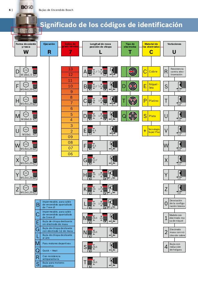
SPARK PLUG: FUNCTIONS, CONSTRUCTION, WORKING PRINCIPLE AND TYPES
A spark plug is an electrical device that fits into the cylinder head of some internal combustion engines and ignites compressed aerosol gasoline by means of an electric spark. Spark plugs have an insulated center electrode which is connected by a heavily insulated wire to an ignition coil or magneto circuit on the outside, forming, with a grounded terminal on the base of the plug, a spark gap inside the cylinder.
The spark plug has two primary functions:
1. To ignite the air/fuel mixture. Electrical energy is transmitted through the spark plug, jumping the gap in the plugs firing end if the voltage supplied to the plug is high enough. This electrical spark ignites the gasoline/air mixture in the combustion chamber.
2. To remove heat from the combustion chamber. Spark plugs cannot create heat, they can only remove heat. The temperature of the end of the plug\’s firing end must be kept low enough to prevent pre-ignition, but high enough to prevent fouling. The spark plug works as a heat exchanger by pulling unwanted thermal energy from the combustion chamber and transferring heat to the engines cooling system. The heat range of a spark plug is defined as its ability dissipate heat from the tip.
CONSTRUCTION
1. Ribs- Insulator ribs provide added protection against secondary voltage or spark flashover and also help to improve the grip of the rubber spark plug boot against the plug body. The insulator body is molded from aluminum oxide ceramic. In order to manufacture this part of the spark plug, a high-pressure, dry molding system is utilized. After the insulator is molded, it is kiln-fired to a temperature that exceeds the melting point of steel. This process results in a component that features exceptional dielectric strength, high thermal conductivity and excellent resistance to shock.
2. Insulator: The insulator body is molded from aluminum oxide ceramic. In order to manufacture this part of the spark plug, a high-pressure, dry molding system is utilized. After the insulator is molded, it is kiln-fired to a temperature that exceeds the melting point of steel. This process results in a component that features exceptional dielectric strength, high thermal conductivity and excellent resistance to shock. The pointer shows the spark plug insulator. As mentioned above, it is formed from aluminum oxide ceramic. The outer surface is ribbed to provide grip for the spark plug boot and to simultaneously add protection from spark flashover (crossfire).
3. Hex: The hexagon provides the contact point for a socket wrench. The hex size is basically uniform in the industry and is generally related to the spark plug thread size.
4. Shell: The steel shell is fabricated to exact tolerances using a special cold extrusion process. Certain types of spark plugs make use of a steel billet (bar stock) for shell construction.
5. Plating: The shell is almost always plated. This enhances durability and provides for rust and corrosion resistance. The steel shell is fabricated to exact tolerances using a special cold extrusion process or in other specialized cases, machined from steel billet. The hexagon machined onto the shell allows you to use a socket wrench to install or remove the plug.
6. Gasket: Certain spark plugs use gaskets while other examples are “gasketless.” The gasket used on spark plugs is a folded steel design that provides a smooth surface for sealing purposes. Gasketless spark plugs use a tapered seat shell that seals via a close tolerance incorporated into the spark plug.
7. Threads: Spark plug threads are normally rolled, not cut. This meets the specifications set forward by the SAE along with the International Standards Association.
8. Ground electrode: There are a number of different ground electrode shapes and configurations, but for the most part, they are manufactured from nickel alloy steel. The ground electrode must be resistant to both spark erosion and chemical erosion, both under massive temperature extremes.
9. Center electrode: Center electrodes must be manufactured from a special alloy that is resistant to both spark erosion and chemical corrosion. Keep in mind that combustion chamber temperatures vary (and sometimes radically). The center electrode must live under these parameters.
10. Spark park electrode gap: The area between the ground electrode and the center electrode is called the gap. Center electrodes must be manufactured from a special alloy that is resistant to both spark erosion and chemical corrosion.
11. Insulator nose: There are a large number of insulator nose shapes and sizes available, but in essence, the insulator nose must be capable of shedding carbon, oil and fuel deposits at low speeds. At higher engine speeds, the insulator nose is generally cooled so that temperatures and electrode corrosion are reduced.
WORKING PRINCIPLE
The spark plug is connected to a high voltage source like the magneto or the ignition coil at one end. The other end with the two electrodes is immersed into the combustion chamber. When current passes through the terminal and into the main center electrode, a potential difference (voltage drop) is created between two electrodes. The gas mixture that occupies the gap between them acts as an insulator and thus the electricity doesn’t flow beyond the tip of the center electrode.
But as the voltage increases, the gases in the gap begin to get energized. Once the voltage increases to the point that crosses the dielectric strength (resistance to conduct electricity) of the gases, they become ionized. Once the gases get ionized, they begin to act as conductors and permit the current to travel through the insulating gap. When the dielectric strength is crossed, the electrons begin to surge through that gap. This sudden movement of electrons rapidly increases the heat in that region due to which they begin to expand rapidly causing a mini explosion which results in the formation of a spark.
TYPES
Spark Plugs can be put into two different primary classifications, based on their operating temperatures and based on their construction.
Based on Operating Temperatures
Once the combustion process is completed in the combustion cycle, the heat generated needs to dissipate. The heat escapes through the exhaust gases, the cylinder wall of the engine and the spark plug surface. Based on the operating temperature and level of heat dissipation, spark plugs can be classified into two types:
1. Hot Spark Plug: A hot spark plug operates in a higher temperature range. It has a lesser ceramic area which is used to insulate the heat. A hot spark plug dissipates lesser combustion heat and allows the tip and electrode to stay hotter. This ensures that any deposit accumulation is burned off and isn’t allowed to stay for long.
2. Cold Spark Plug: For high-performance engines that run hot by default, using a hot spark plug will cause pre-ignition. In extreme cases, it can also lead to the tip melting off. In such cases, a cold spark plug is used. Here the ceramic insulation area is higher and this it will dissipate more heat. But on the flipside, it is prone to greater deposit accumulation. Be sure to follow your instruction manual and use the correct type of plug recommended for your engine for optimum performance.
Based on Material Used
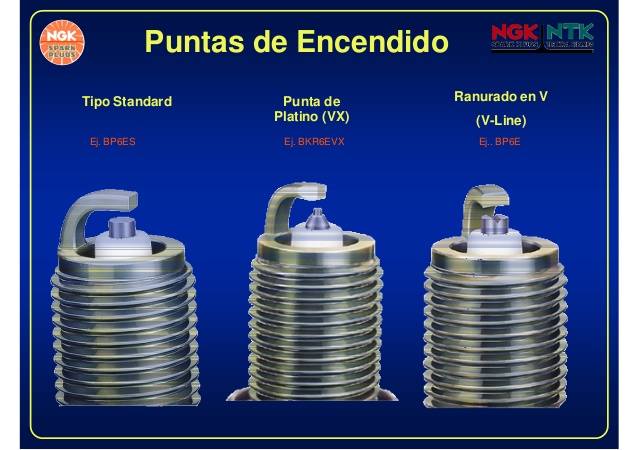
Spark Plugs are further classified based on the material used on the ends of the electrodes. They are of 4 types:
1. Copper- Nickel Type: These are the most basic types of spark plugs. Here the center electrode is made of a copper-nickel alloy as copper on its own is very weak and will melt off due to engine heat. Nickel is added to strengthen the plug but even then these are the weakest types available in the market. They are also required to be made with a larger diameter and hence require more voltage for operation.
2. Single Platinum Type: These plugs have a small platinum disc on the tip of the center electrode. This platinum tip is exponentially stronger than a copper-nickel coating making this type of plug last long as well. They are also less prone to debris build up.
3. Double Platinum Type: These plugs have platinum tips on both the center electrode and the side electrode. They spark up twice in the combustion cycle, once before the combustion and once during the exhaust stroke. The second spark is wasted and so this spark plug can only be used if your vehicle is equipped with a waste spark ignition type distributor.
4. Iridium Type: These are the best spark plugs available in the market. Here the tip of the center electrode is made of Iridium which is the strongest out of nickel, copper, and platinum. Hence, they are the least prone to deposits and damage. They also have a small sized electrode which requires less voltage for operation as well. Iridium plugs are much more expensive than the other types but then again you pay for what you get.
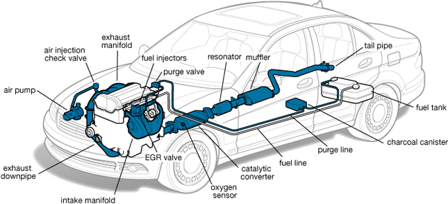
The exhaust system collects the exhaust gases from the cylinders, removes harmful substances, reduces the level of noise and discharges the purified exhaust gases at a suitable point of the vehicle away from its occupants…
FUNCTION
The exhaust system collects the exhaust gases from the cylinders, removes harmful substances, reduces the level of noise and discharges the purified exhaust gases at a suitable point of the vehicle away from its occupants. The exhaust system can consist of one or two channels depending on the engine. The flow resistance must be selected so that the exhaust back pressure affects engine performance as little as possible. To ensure that the exhaust system functions perfectly, it must be viewed as a whole and developed accordingly. This means that its components must be coordinated by the design engineers in line with the specific vehicle and engine.
In addition to all the complex functions which the exhaust system has to perform, it is also subject to extreme stresses. The fuel-air mixture in the cylinders is abruptly heated to temperatures up to 2,400 °C. This causes it to expand greatly before escaping into the exhaust system at supersonic speed. This noise level resembles the crack of an explosion and must be reduced by approx. 50 dB(A) as it travels from the engine exhaust valve to the end of the exhaust system.
Apart from temperature and pressure stresses, the exhaust system must also cope with vibrations from the engine and bodywork as well as vibrations and jolting from the carriageway. The exhaust system additionally has to resist corrosion attacking from the inside caused by hot gases and acid, and from the outside in the form of moisture, splashed water and salt water. There is also the risk that the catalyst may be poisoned through sulfur or lead present in the fuel.
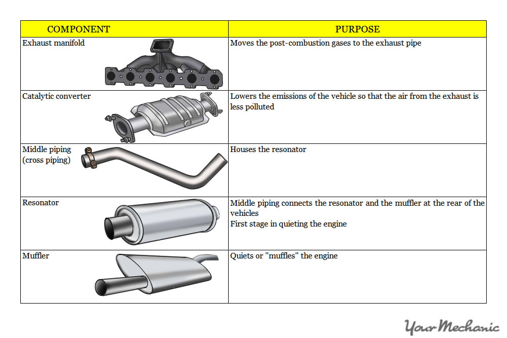
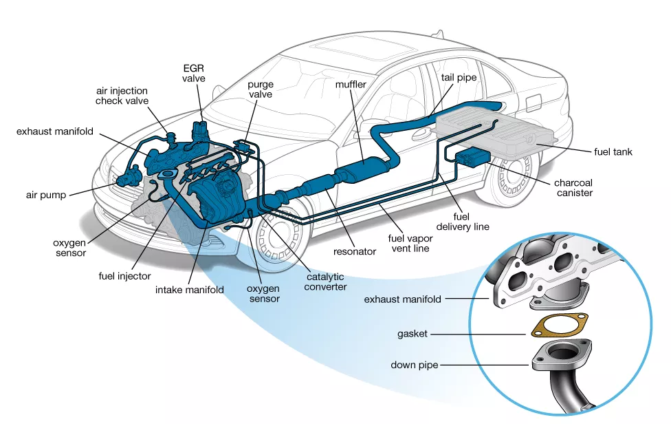
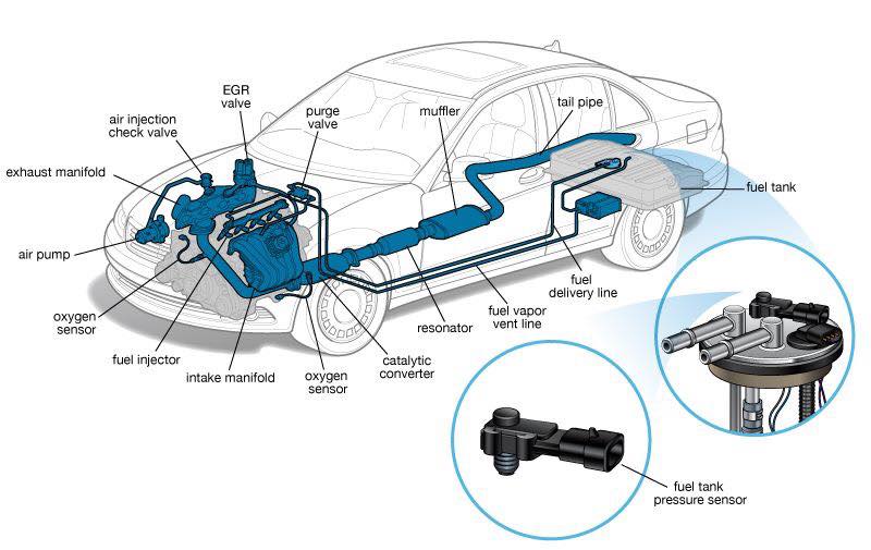
COMPONENTS OF EXHAUST SYSTEM
1. Exhaust manifold:
The exhaust manifold attaches to the cylinder head and takes each cylinder’s exhaust and combines it into one pipe. The manifold can be made of steel, aluminum, stainless steel, or more commonly cast iron.
2. Oxygen sensor:
All modern fuel injected cars utilize an oxygen sensor to measure how much oxygen is present in the exhaust. From this, the computer can add or subtract fuel to obtain the correct mixture for maximum fuel economy. The oxygen sensor is mounted in the exhaust manifold or close to it in the exhaust pipe.
3. Catalytic converter:
This muffler like part converts harmful carbon monoxide and hydrocarbons to water vapor and carbon dioxide. Some converters also reduce harmful nitrogen oxides. The converter is mounted between the exhaust manifold and the muffler.
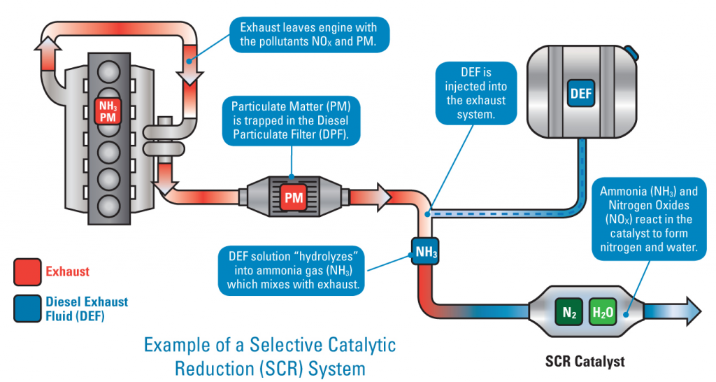
Selective Catalytic Reduction (SCR)
This technology uses ammonia to break down dangerous NOx emissions produced by diesel engines into nitrogen and water. In automotive applications, SCR delivers ammonia through a urea solution – Diesel Exhaust Fluid (DEF) – which is sprayed into the exhaust stream by an advanced injection system and then converted into ammonia on a special catalyst.
SCR is the technology of choice for the majority of truck and engine manufacturers to meet 2010 emissions standards for heavy-duty trucks.
Aside from helping the environment, the biggest benefit of SCR for vehicle owners is the fuel efficiency the technology provides. Because SCR deals with emissions in the exhaust pipe, engineers are able to tune the engine to provide more torque and reduce fuel consumption.
4. Muffler/Silencer:
Every internal combustion engine produces «exhaust noise» due to the pulsating emission of gases from the cylinders. This noise has to be silenced by reducing the sound energy of the exhaust gas flow. There are two basic options here: Absorption and reflection of the sound in the silencer. These two principles are generally combined in a single silencer. Exhaust chambers and exhaust flaps are other sound-absorbing and sound-modifying elements that can be used to eliminate especially undesirable frequencies from the outlet noise. Catalytic converters also have a sound-absorbing effect.
The exhaust system is itself a system subject to vibration, it produces noise itself through natural frequencies and vibration which are transmitted to the car body. Careful coordination of the entire system is, therefore, necessary here. This includes the design and positioning of the individual elements of the exhaust system and their flexible mountings.
The muffler serves to quiet the exhaust down to acceptable levels. Remember that the combustion process is a series of explosions that create a lot of noise. Most mufflers use baffles to bounce the exhaust around dissipating the energy and quieting the noise. Some mufflers also use fiberglass packing which absorbs the sound energy as the gases flow through.
5. Resonator
The muffler alone cannot always quiet all the engine noise. Many exhaust systems also include a resonator which is like a mini-muffler. They are usually straight pipes filled with sound muffling materials. The resonator can be either before or after the muffler in the exhaust system.
6. Exhaust pipe:
Between all of the above mention parts is the exhaust pipe which carries the gas through it’s journeys out your tailpipe. Exhaust tubing is usually made of steel but can be stainless steel (which lasts longer due to its corrosion resistance) or aluminized steel tubing. Aluminized steel has better corrosion resistance than plain steel but not better than stainless steel. It is, however, cheaper than stainless steel.
HOW TO IDENTIFY PROBLEMS
Although the exhaust system is located underneath the vehicle, there are some symptoms you can look out for which may indicate that there is a problem with your exhaust.
1.Noises
A loud roaring noise could indicate corrosion to the exhaust system A hissing sound could mean that gas is escaping through a crack or hole in one of the exhaust components Chugging noises mean that there may be a blockage in one of the pipes A persistent and rapid succession of knocking sounds indicate that a part of the exhaust may have come loose
2. Emissions
White smoke – this is not smoke but in fact, vapor and you should see this when you first start your car as it indicates that the engine is warming up. If white smoke is visible after the engine is warm it may indicate internal leaks or cracks.
Blue smoke – A bluish-grey smoke means that oil may be burning in the combustion chamber. This could mean that the cylinder is worn or there are leaks in the valve seals.
Black smoke – very black smoke is often accompanied by increased fuel consumption and may signify leaks in the exhaust system or a problem with the engine.
3. Visual
Inspect the components of your exhaust that you can see for any signs of rust or corrosion. Make sure you keep an eye out for any cracks and holes and contact a specialist if you do find any signs of damage.
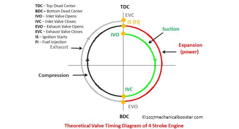
A valve timing diagram is a graphical representation of the opening and closing of the intake and exhaust valve of the engine, The opening and closing of the valves of the engine depend upon the movement of piston from TDC to BDC, This relation between piston and valves is controlled by setting a graphical representation between these two, which is known as valve timing diagram.
The valve timing diagram comprises of a 360 degree figure which represents the movement of the piston from TDC to BDC in all the strokes of the engine cycle, Which is measured in degrees and the opening and closing of the valves is controlled according to these degrees.
WHY DO WE NEED VALVE TIMING DIAGRAM?
The normal engine completes around 100000 cycles per minute, as we know there are number of processes involve in a single cycle (from the intake of the air-fuel mixture to the exhaust of the combustion residual) of a internal which makes it necessary to be equipped with an effective system that can enable
Synchronisation between the steps of a cycle of the engine from intake of air-fuel ratio to the exhaust of combustion residual. Complete seizure of the combustion chamber at the instant at which the combustion of air-fuel mixture takes place as the leakage can cause damage to the engine and can be hazardous. Provide engine with a mixed air and fuel or air in case of diesel engine when required ( at the time of suction) which is the necessity of the engine. Provide the exit for the combustion residual so that the next cycle of the engine can take place. Ideal timing for the opening and closing of the inlet and outlet valve which in turn protect the engine from defects like knocking or detonation. A high compression ratio required to combust the fuel especially in case of diesel engine by overlapping the closing of the valve. The cleaning of engine cylinder which in turn maintain the quality of combustion and decreases wear and tear inside the cylinder. The study of the details of the combustion that is required for the modification of the power of the engine. So due to these reasons a engine weather it is 2-stroke or 4-stroke is designed according to the valve timing diagram, so that the movement of piston from TDC to BDC is provided with the ideal timing of opening and closing of the intake and exhaust valves respectively.
VALVE TIMING DIAGRAM FOR 4-STROKE ENGINE (PETROL AND DIESEL)
As we all know in 4-stroke engine the cycle completes in 4-strokes that are suction, compression, expansion and exhaust , The relation between the valves (inlet and outlet) and piston movement from TDC to BDC is represented by the graph known as valve timing diagram.
THEORETICAL
Suction Stroke-
The engine cycle starts with this stroke, Inlet valve opens as the piston which is at TDC starts moving towards BDC and the air-fuel mixture in case of petrol and fresh air in case of diesel engine starts entering the cylinder,till the piston moves to BDC.
Compression Stroke-
After the suction stroke the piston again starts moving from BDC to TDC in order to compress the air-fuel (petrol engine) and fresh air (diesel engine) which in turn raises the pressure inside the cylinder which is essential for the combustion of the fuel. The inlet valve closes during this operation to provide seizure of the chamber for the compression of the fuel.
Expansion Stroke-
After compressing the fuel, The combustion of the fuel takes place which in turn pushes the piston which is at TDC towards BDC in order to release the pressure developed by the combustion and output is obtained . Note – In petrol engine combustion takes place due to the spark produced by the spark plug. In petrol engine the air and fuel charge enters the cylinder during suction stroke. In diesel engine combustion occurs due to the high compression provided by the compression stroke which is responsible for raising the temperature inside cylinder upto auto-ignition temperature of the diesel and air charge. In diesel engine the fresh air enters inside the cylinder during suction stroke and the fuel is sprayed by the fuel injectors over the air.
Exhaust Stroke-
After expansion stroke the piston which is at BDC starts moving towards TDC followed by the opening of exhaust valve for the removal of the combustion residual Exhaust valve closes after the piston reaches TDC.
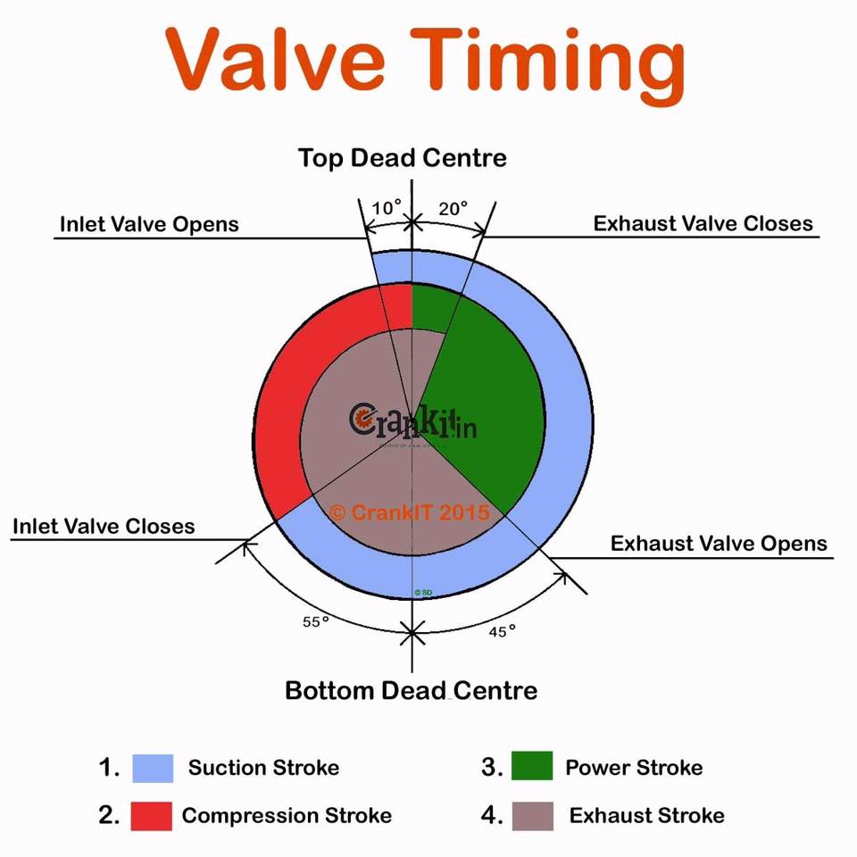
ACTUAL OR PRACTICAL PROCESS
In suction stroke of 4-stroke engine the inlet valve opens 10-20 degree advance to TDC for the proper intake of air-fuel(petrol) or air (diesel) ,which also provides cleaning of remaining combustion residuals in the combustion chamber. When the piston reaches BDC the compression stroke starts and again the piston starts moving towards TDC ,The inlet valve closes 25-30 degree past the BDC during the compression stroke,which provide complete seizure of the combustion chamber for the compression of air-fuel(petrol engine)and air(diesel engine).
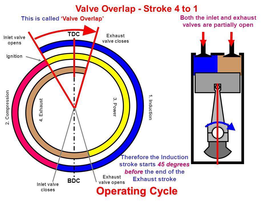
During the compression stroke as the piston moves towards TDC ,combustion of fuel takes place 20-35 degree before TDC which provides the proper combustion of fuel and proper propagation of flame. The expansion strokes starts due to the combustion of fuel which in turn releases the pressure inside the combustion chamber and provide rotation to the crank shaft,The piston moves from TDC to BDC during expansion stroke which continuous 30-50 degree before BDC. The exhaust valve opens 30-50 degree before BDC which in turn starts the exhaust stroke and the exhaust of the combustion residual takes place with movement of the piston from BDC toTDC which continues till the 10-20 degree after the piston reaches TDC. As we can see in the entire cycle of engine valves overlap 2 times i.e. closing of both valves during compression stroke and opening of both valves during exhaust stroke.
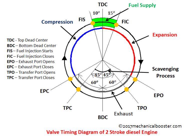
VALVE TIMING DIAGRAM FOR 2-STROKE ENGINE
In 2-stroke petrol engine as we all know the engine cycle completes in 2-strokes i.e expansion stroke and compression stroke, The fuel intake and combustion residual exhaust occurs respectively during these 2 strokes.
THEORETICAL VALVE TIMING
Expansion stroke-
At the beginning of the expansion stroke the piston which is at TDC starts moving towards BDC due to the combustion of compressed air-fuel (petrol engine) and (diesel sprayed charge in diesel engine) during compression stroke and the power output is obtained. The air-fuel(petrol engine) and air (diesel diesel) enters through the inlet port during the expansion strokes as the piston moves from TDC to BDC during this stroke. The expansion stroke continuous till the piston reaches BDC.
Compression Stroke-
At the end of the expansion stroke the piston which is at BDC starts moving towards TDC and the compression of air-fuel(petrol engine) and diesel sprayed charge(diesel engine) starts along with the exhaust of combustion residual through exhaust port due to the movement of piston from BDC to TDC. The piston closes both inlet port and exhaust port due to its movement from BDC to TDC which in turn raises the pressure inside the combustion chamber. At the end of the compression stroke i.e. when the piston reaches TDC combustion of the air-fuel (petrol engine) due to spark and diesel sprayed charge (diesel engine) due to the high pressure takes place, And the cycle repeats again.
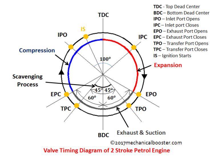
ACTUAL OR PRACTICAL PROCESS
Before the expansion stroke i.e. completion of the compression stroke, the inlet port open 10-20 degree before the piston reaches the TDC which in turn starts the expansion stroke due to the combustion of air-fuel (petrol engine) from the crankcase and air (diesel engine) entered from the inlet port which in turn pushes the piston towards BDC. The inlet port closes 15-20 degree after TDC during the expansion stroke of the 2-stroke engine. Due to the movement of piston from TDC to BDC during expansion stroke exhaust port opens 35-60 degree before the piston reaches BDC which in turn starts the exhaust of the combustion residual.. Transfer port open 30-45 degree before BDC for scavenging process. When the piston moves towards TDC from BDC the transfer port closes 30-45 degree after BDC which in turn stops the scavenging process. During the movement of piston from BDC to TDC exhaust valve closes 35-60 degree after BDC which seizes the combustion chamber and pressure inside the combustion chamber increases due to the start of compression stroke.and the cycle starts again. The air fuel mixture (petrol engine) and air ( diesel engine) is transported to the cylinder during the opening of the transfer port. Note – The opening and closing of valves few degrees before TDC and BDC is required for normal working of the engine as this degree gaps provides proper completion of the operation of strokes and prevents the engine from defects like knocking, and also causes less emission. For power modification this valve timing is adjusted which in turn increases the power and torque of the engine but decreases the economy. In this article we have learnt about valve timing diag
A piston is a cylindrical engine component that slides back and forth in the cylinder bore by forces produced during the combustion process. The piston acts as a movable end of the combustion chamber. The stationary end of the combustion chamber is the cylinder head. Pistons are commonly made of a cast aluminum alloy for excellent and lightweight thermal conductivity. Thermal conductivity is the ability of a material to conduct and transfer heat.
Aluminum expands when heated, and proper clearance must be provided to maintain free piston movement in the cylinder bore. Insufficient clearance can cause the piston to seize in the cylinder. Excessive clearance can cause a loss of compression and an increase in piston noise.
There are also secondary functions fulfilled by the piston:
contributes to heat dissipation generated during combustion ensures the sealing of the combustion chamber, preventing gas leakages from it and oil penetration into the combustion chamber guides the movement of the connecting rod ensures to the continuous change of gases in the combustion chamber generates the variable volume in the combustion chamber
The piston is the component of the internal combustion engine (ICE) which has to sustain the most mechanical and thermal stress. Due to the piston, the power of the ICE is limited. In case of very high thermal or mechanical stress, the piston is the first component to fail (compared to engine block, valves, cylinder head). This is because the piston must be a compromise between mass and mechanical and thermal stress resistance.
The geometry of the piston is constrained due to the cubic capacity of the ICE. Therefore, the main way to increase the mechanical and thermal resistance of the piston is by increasing its mass. This is not recommended because a piston with high mass, has high inertia which translates in high dynamic forces, especially during high engine speed. The resistance of the piston can be improved by geometry optimization but there will be always a compromise between mass and mechanical and thermal resistance.
As you can see there are significant differences between diesel and gasoline pistons. Diesel pistons must withstand higher pressures and temperatures, therefore they are bigger, bulkier and heavier. They can be manufactured from aluminium alloys, steel or a combination of both. Gasoline engine pistons are lighter, designed for higher engine speeds. They are manufactured from aluminium alloys.
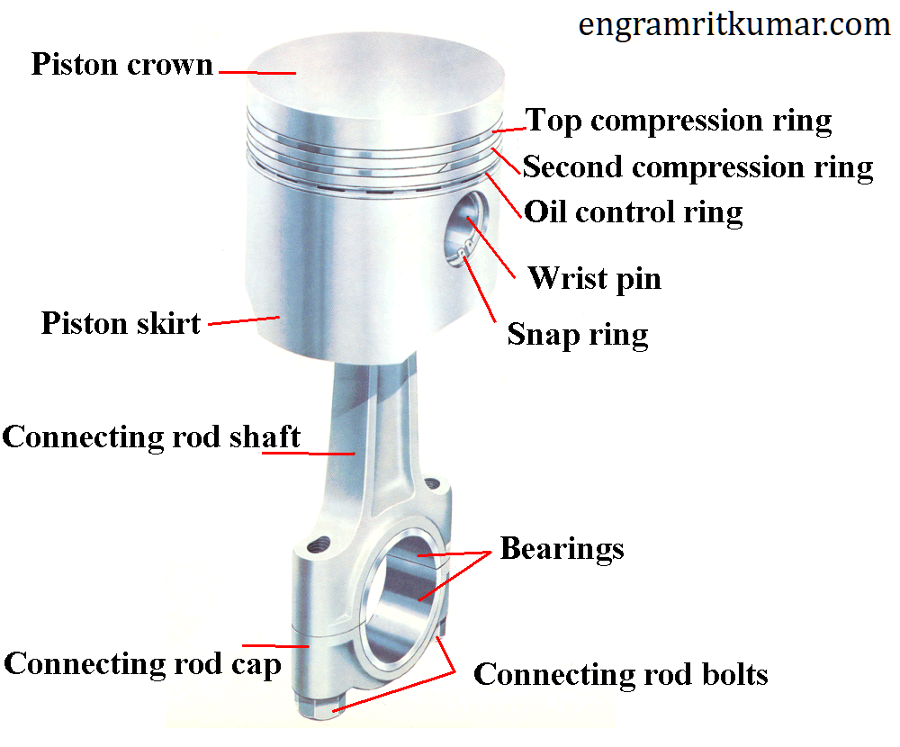
The piston crown comes in direct contact with the burning gases, within the combustion chamber, so it’s exposed to high thermal and mechanical stress. Depending on the type of the engine (diesel or gasoline) and the type of fuel injection (direct or indirect injection), the piston crown can be flat or can contain a bowl.
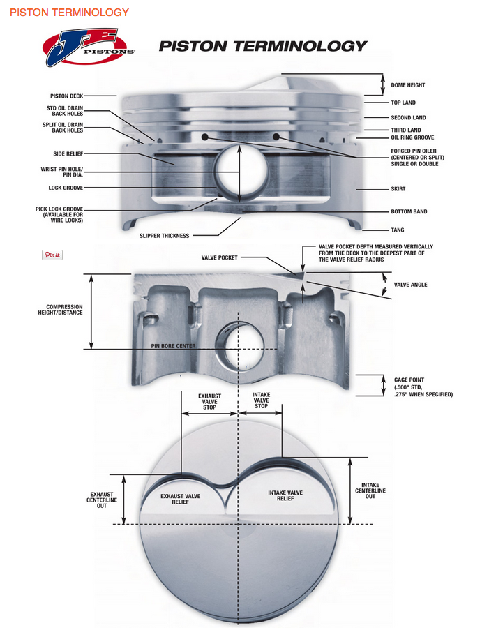
PISTON PARTS
1. piston pin 2. skirt 3. ring grooves 4. ring lands, and 5. piston rings.
1. Piston head It is the top surface (closest to the cylinder head) of the piston which is subjected to tremendous forces and heat during normal engine operation.
2. Piston pin bore A piston pin bore is a through hole in the side of the piston perpendicular to piston travel that receives the piston pin.
3. Piston pin A piston pin is a hollow shaft that connects the small end of the connecting rod to the piston.
4. Skirt The skirt of a piston is the portion of the piston closest to the crankshaft that helps align the piston as it moves in the cylinder bore. Some skirts have profiles cut into them to reduce piston mass and to provide clearance for the rotating crankshaft counterweights.
5. Ring grooves A ring groove is a recessed area located around the perimeter of the piston that is used to retain a piston ring.
6. Ring land Ring lands are the two parallel surfaces of the ring groove which function as the sealing surface for the piston ring.
7. Poston ring A piston ring is an expandable split ring used to provide a seal between the piston an the cylinder wall. Piston rings are commonly made from cast iron. Cast iron retains the integrity of its original shape under heat, load, and other dynamic forces. Piston rings seal the combustion chamber, conduct heat from the piston to the cylinder wall, and return oil to the crankcase. Piston ring size and configuration vary depending on engine design and cylinder material.
Piston rings commonly used on small engines include:
1. Compression Ring 2. Wiper Ring 3. Oil Ring
1. Compression ring, A compression ring is the piston ring located in the ring groove closest to the piston head. The compression ring seals the combustion chamber from any leakage during the combustion process. When the air-fuel mixture is ignited, pressure from combustion gases is applied to the piston head, forcing the piston toward the crankshaft. The pressurized gases travel through the gap between the cylinder wall and the piston and into the piston ring groove. Combustion gas pressure forces the piston ring against the cylinder wall to form a seal. Pressure applied to the piston ring is approximately proportional to the combustion gas pressure.
2. Wiper ring A wiper ring is the piston ring with a tapered face located in the ring groove between the compression ring and the oil ring. The wiper ring is used to further seal the combustion chamber and to wipe the cylinder wall clean of excess oil. Combustion gases that pass by the compression ring are stopped by the wiper ring.
3. Oil ring An oil ring is the piston ring located in the ring groove closest to the crankcase. The oil ring is used to wipe excess oil from the cylinder wall during piston movement. Excess oil is returned through ring openings to the oil reservoir in the engine block. Two-stroke cycle engines do not require oil rings because lubrication is supplied by mixing oil in the gasoline, and an oil reservoir is not required.
TYPES OF PISTONS
There are three types of pistons, each named for its shape: flat top, dome, and bowl.
1. Dome Piston The Dome Piston looks just like it sounds. Instead of a flat top it has a dome that looks like the top of a dome stadium. Piston Dome refers to the amount of added volume on top of the piston compared to a flat top piston. This added volume increases the Compression Ratio and therefore should increase performance. However, depending on the shape of the combustion chamber in the head, highly domed pistons can create slow burning, inefficient combustion chambers. The optimum tradeoff between higher compression ratio and dome/combustion chamber shape can only be determined by trial-and-error on a dyno. Dome Pistons are also used in 2 stroke engines, mostly to deflect the inlet charge up toward the spark plug, and not let it flow directly to the exhaust ports.
2. Bowl Piston Bowl pistons typically are used to reduce compression ratio because of the added volume of the bowl to the combustion volume. Because they reduce Compression Ratio, bowl pistons can be used in Turbo Charged or Super Charged engines to help avoid detonation (spark knock) under boosted conditions. The extreme bowl shown is used in diesel engines, where the bowl is used to confine the diesel fuel spray for good, fast combustion. A piston bowl can do the same for a spark ignition engine and make for a fast burning, compact combustion chamber.
3. Flat Top Piston The Flat Top Piston is just like it sounds; it has a flat top. These pistons are typically used in mass produced engines. They are easy to manufacture and this keeps the cost of the engines low.
4. Flat Top Piston with Valve Relief The Flat Top with Valve Relief is basically a Flat Top Piston but they have small amounts of material removed to keep the valves from hitting the piston when the intake and exhaust valves are opening or closing. This allows for higher compression ratios by allowing the piston to go higher into the cylinder head.
The Electric Park Brake functions as a conventional hydraulic brake for standard service brake applications, and as an electric brake for parking and emergency braking.
Electric Park Brake (EPB) is a caliper with an additional motor (motor on caliper) that operates the parking brake. The EPB system is electronically controlled and consists of the EPB switch, the EPB caliper and the electronic control unit (ECU).
The electric parking brake or the EPB is an advanced version of conventional parking brake or handbrake. Sometimes, people also refer to this system as ‘Electronic Parking Brake’. Technically this system is a sub-part of ‘Brake by Wire’ system.
The main function of parking brakes is to avoid motion of vehicle when parked. In addition, these brakes also play an important role in avoiding backward motion of vehicle which resumes moving on a slope. Generally, parking brakes operate only on the rear wheels of a vehicle.
EPB functionality relies on four elements:
1. control switches, 2. a wheel-speed sensor, 3. a force sensor, and 4. electric motors.
Together, these monitor a variety of input signals and determine when to apply or release the brakes.
COMPONENTS
However, in Electric Parking Brake, no such cable connection exists. Instead, it works with the help of following main components:
1. Electronic Brake Module 2. Actuator or electric motor 3. Electric Switch in cabin
WORKING PRINCIPLE
Conventional parking brakes employ a cable that connects handbrake lever and brake shoes. When the driver operates the lever, tension in the cable increases thereby forcing the brake shoe (or pads) on brake drum (or disc). Thus, wheels cannot move further. When the driver operates the switch, it sends a command to Module which senses that parking brakes are required to be operated. Later, this module commands the actuators or electric motors installed in the brake calipers to operate. Thus, brake pads are forced on the disc thereby restricting the movement of wheels. Due to the use of electronic components, the operation of this system is almost instantaneous and efficient. Also, it improves the reliability of braking because of the absence of mechanical connection. This brake deactivates automatically when the driver presses the accelerator pedal. Some vehicle manufacturers also integrate Assist function with this system.
TYPES OF EPB
1. Cable-pull systems
The cable pull system is simply a development of the traditional lever and cable method. As the switch is operated, a motor, or motors, pull the cable by either rolling it on a drum or using an internally threaded gear on a spiral attached to the cable. The electronic parking brake module shown as figure 1, also known as the EPB actuator, is fitted to some Range Rover and Landrover models. The parking brake can be released manually on most vehicles. After removing a plastic cover or similar, pulling a wire cable loop will let off the brake.
2. Electric-hydraulic caliper systems
These types are usually employed as part of a larger control system such as an electronic stability program (ESP). When the driver presses the switch to activate the parking brake, the ESP unit automatically generates pressure in the braking system and presses the brake pads against the disc. The calipers are then locked in position by an electrically controlled solenoid valve. The caliper remains locked without any need for hydraulic pressure. To release the brake, the ESP briefly generates pressure again, slightly more than was needed to lock the caliper, and the valve is released.
3. Full electric drive-by-wire systems
The drive-by-wire system shown in figure 3 was developed by Continental. It uses an electric motor (3) and gearbox to apply pressure on the pads and therefore on to the disc. A key component is the parking brake latch. This is like a ratchet and it prevents the pressure in the piston from rotating the motor – and it therefore keeps the brakes applied.
ADVANTAGES AND DISADVANTAGE
Advantages
• Modular architecture, scalable clamp load and durability with reduced hysteresis • Significant weight savings compared to mechanical park brake systems to support enhanced fuel economy and reduced emissions • Vehicle coverage from small car to light truck segments • Electronic control allows for integration with other safety technologies • Pioneered EPB technology in 2000 and now in fifth generation with more than 90 million EPB calipers on world roadways • The response time of this system is very short. • The operation is highly reliable. • Improves control of the vehicle while starting from standstill condition on a slope.
Disadvantages
1. This system is costly. 2. It needs a skilled professional for troubleshooting.
Anti-lock Braking System is a closed-loop control device that prevents wheel lock-up during braking and as a result vehicle stability and steering is maintained. This system uses the principle of cadence braking and threshold braking.
The purpose of Anti-lock Braking System (ABS) is to control the rate at which individual wheels accelerate and de-accelerate through the regulation of the line pressure applied to each foundation brake. The control signals, generated by the controller and applied to the brake pressure modulating unit, are derived from the analysis of the outputs taken from wheel speed sensors. Thus, when active, the Anti-lock Braking System (ABS) makes optimum use of the available friction between the tires and the road surface.
COMPONENTS OF ABS
There are four main components of the ABS:
1. Speed sensor
The purpose of the speed sensor is to monitor the speed of each wheel and then to determine the acceleration and de-acceleration of the wheels. It consists of the exciter(a ring with notched teeth)and a wire coil/magnet assembly which generates the pulses of electricity as teeth of exciter pass in front of it.
2. Valves
The function of the valves is to regulate the air pressure to brakes during the Anti-Lock Braking System (ABS) action. They are placed in the brake line of each brake controlled by the ABS. In most of the cases, the valve has three positions:
* In position one, the valve is open and the pressure from the master cylinder is passed through the brake.
* In position two, the valve blocks the line resulting in isolating the brake from the master cylinder.
* In position three, the valve releases some of the pressure from brakes.
3. Pump
The purpose of the pump is to regulate or restore the pressure back to the brakes that have been released by the valves.
4. Controller
The controller of the Anti-Lock Braking System (ABS) consists of the Electronic Control Unit(ECU) which processes all the ABS information and signal functions. The ECU gets the information from all the wheels and then control or limit the brake force to each wheel.
ABS BRAKE TYPES
Anti-lock braking system or ABS has different types of brakes based on the number of channels used.
1. Four-channel
This scheme is employed in most of the modern cars like Ferrari’s California T. In this scheme all the four wheels have there owned individual speed sensors and valves. This gives the best result as all the four wheels can be controlled individually which ensures the maximum braking force.
2. Three-channel
Three-channel comes with two combinations, one is three-channel with four sensors and the other one with three-channel and three sensors.
In three-channel and four sensor scheme, along with the four sensors on each wheel, there is a separate valve for each of the front wheels and a common valve for the rear wheels.
The three-channel and three sensor scheme are mostly employed in pickup trucks. There are individual sensors and valves for both the front wheels with a common valve and sensor for both of the rear wheel.
3. Two-channel
This system works with four sensors and two valves. It uses speed sensors at each wheel, with one control valve for both of the front wheels and the other one for the rear wheels.
4. One channel
This system is found on pickup trucks which use rear-wheel ABS. It has one valve and one sensor for both of the rear wheels. This system is not very effective because as there is a possibility that one of the rear wheels will lock, reducing the effectiveness of brakes.
WORKING OF ABS
* When the brakes are applied, fluid is forced from the master cylinder to the HCU inlet ports with the help of open solenoid valves that are contained in the HCU, then through the outlet ports of HCU to each wheel.
* The rear part of the master cylinder feeds the front brakes and vice-versa.
* After the fluid is inserted in each wheel, the wheel starts locking-up.
* When the control module senses that wheel is going to lock up, it closes the normally open solenoid valves for that wheel.
* The anti-lock brake control module then looks at anti-lock brake sensor signal from the affected wheel.
* Once the affected wheel comes back up to the speed, then the control module returns the solenoid valve to there normal condition.
A torque converter is a type of fluid coupling which is used to transfer rotating power from the engine of a vehicle to the transmission. It takes place of a mechanical clutch in an automatic transmission. The main function of it is to allow the load to be isolated from the main power source. It sits in between the engine and transmission. It has the same function as the clutch in manual transmission. As the clutch separates the engine from the load when it stops, in the same way, it also isolates the engine from the load and keeps engine running when a vehicle stops.
Cars with automatic transmissions don’t have clutches, so they need a way to let the engine keep running while the wheels and gears in the transmission come to a stop. Manual transmission cars use a clutch that disconnects the engine from the transmission. Automatic transmissions use a torque converter.
When the engine is idling, such as at a stoplight, the amount of torque going through the torque converter is small but still enough to require some pressure on the brake pedal to stop the car from creeping. When you release the brake and step on the gas, the engine speeds up and pumps more fluid into the torque converter, causing more power (torque) to be transmitted to the wheels.
FUNCTIONS OF TORQUE CONVERTER
Its main functions are:
1. It transfers the power from the engine to the transmission input shaft. 2. It drives the front pump of the transmission. 3. It isolates the engine from the load when the vehicle is stationary. 4. It multiplies the torque of the engine and transmits it to the transmission. It almost doubles the output torque.
PARTS OF TORQUE CONVERTER
The torque converter has three main parts
1. Impeller or Pump
The impeller is connected to the housing and the housing connected to the engine shaft. It has curved and angled vanes. It rotates with the engine speed and consists of automatic transmission fluid. When it rotates with the engine, the centrifugal force makes the fluid move outward. The blades of the impeller are designed in such a way that it directs the fluid towards the turbine blades. It acts as a centrifugal pump which sucks the fluid from the automatic transmission and delivers it to the turbine.
2. Stator:
The stator is located in between the impeller and turbine. The main function of the stator is to give direction to the returning fluid from the turbine so that the fluid enters the impeller in the direction of its rotation. As the fluid enters in the direction of the impeller, it multiplies the torque. So stator helps in the torque multiplication by changing the direction of the fluid and allows it to enter in the direction of the impeller rotation. The stator changes the direction of fluid almost up to 90 degrees. The stator is mounted with a one-way clutch that allows rotating it in one direction and preventing its rotation in other direction. The turbine is connected to the transmission system of the vehicle. And the stator is placed in between the impeller and turbine.
3. Turbine
The turbine is connected to the input shaft of the automatic transmission. It is present on the engine side. It also consists of curved and angled blades. The blades of the turbine are designed in such a way that it can change the direction of the fluid completely that strikes on its blades. It is the change in the direction of the fluid that forces the blades to move in the direction of the impeller. As the turbine rotates the input shaft of the transmission also rotates and made the vehicle to move. The turbine is also having a lock-up clutch at its back. The lock-up clutch comes into play when the torque converter achieves coupling point. the lockup eliminates the loses and improves the efficiency of the converter.
WORKING PRINCIPLE OF TORQUE CONVERTER
For understanding the working principle of the torque converter, let’s take two fans. One fan is connected to the power source and other is not connected with the power source. When the first fan connected to the power source starts moving, the air from it flows to the second fan which is stationary. The air from the first fan strikes on the blades of the second fan and it also starts rotating almost at the same speed to the first one. When the second fan is stopped, it does not stop the first one. The first fan keeps rotating.
On the same principle, the torque converter works. In that, the impeller or pump acts as the first fan which is connected to the engine and turbine act as the second fan which is connected to the transmission system. When the engine runs, it rotates the impeller and due to the centrifugal force the oil inside the torque converter assembly directed towards the turbine. As it hits the turbine blades, the turbine starts rotating. This makes the transmission system rotate and the wheels of the vehicle move. When the engine stops, the turbine also stops rotating but the impeller connected the engine keeps moving and this prevents the killing of the engine.
It has three stages of operations
1. Stall:
During stall (stop) condition of the vehicle, the engine is applying power to the impeller but the turbine cannot rotate. This happens, when the vehicle is stationary and the driver has kept his foot on the brake paddle to prevent it from moving. During this condition maximum multiplication of torque takes place. As the driver removes its foot from the brake paddle and presses the accelerator paddle, the impeller starts moving faster and this set the turbine to move. At this situation, there is a larger difference between the pump and turbine speed. The impeller speed is much greater than the turbine speed.
2. Acceleration:
During acceleration, the turbine speed keeps on increasing, but still, there is a large difference between the impeller and turbine speed. As the speed of the turbine increases the torque multiplication reduces. During acceleration of the vehicle the torque multiplication is less than that is achieved during a stall condition.
3. Coupling:
It is a situation when the turbine achieved approximately 90 percent speed of the impeller and this point is called the coupling point. The torque multiplication seizes and becomes zero and the torque converter behaves just like a simple fluid coupling. At the coupling point, the lock-up clutch comes into play and locks the turbine to the impeller of the converter. This puts the turbine and impeller to move at the same speed. The lock-up clutch engages only when the coupling point is achieved. During coupling, the stator also starts to rotate in the direction of the impeller and turbine rotation.
NOTE:
1. The maximum torque multiplication takes place during stalling condition. 2. The stator remains stationary before coupling point and helps in the torque multiplication. As the coupling attained, stator stops torque multiplication and starts rotating with the impeller and turbine. 3. The lock-up clutch engages when the coupling point is achieved and removes the power losses resulting in increased efficiency.
TYPES OF TORQUE CONVERTER
1. Single-Stage Torque Converters
The beauty of single-stage converters is their tough, reliable simplicity. Each converter consists basically of three elements: the turbine, the stator, and the impeller. Single-stage converters come in two types of housing — stationary and rotating. Depending on the model, single-stage torque converters boast a variety of capabilities: Sumpless single-stage converters with PTO drives are ideal for applications with power-shift transmissions and driving auxiliary hydraulic pumps. High-torque ration converters with stationary housing feature extraordinary hoisting and lowering capabilities. Type Four hydraulic converters are designed specifically for the oil and gas industry.
2. Three Stage Torque Converters
Three-stage torque converters employ three rings of turbine blades, as well as two sets of reactor or stator blades. The effect of this design is increased torque — up to five times the amount of engine output torque, in fact, when the engine is at a stall. Depending on the specific design, three-stage converters are rated for a range of engines, including 335 hp at 2400 rpm, 420 hp at 2200 rpm, and 580 hp at 2,200 rpm. Three-stage converters also come with both stationary and rotating housing.
Advantages
It produces the maximum torque as compared with the vehicle equipped with a clutch. It removes the clutch pedal. It makes the job of driving a vehicle easier.
Disadvantages
Its fuel efficiency is low as compared with the vehicle with manual transmission.
Application
The torque converter is used in the vehicle that is equipped with automatic transmission. It is also used in industrial power transmissions such as conveyor drives, winches, drilling rigs, almost all modern forklifts, construction equipment, and railway locomotives. It is used in marine propulsion systems.
Automotive steering forms the basis of any vehicle’s motion control. It comprises of all components, joints, and linkages required to transfer power from the engine to the wheels. The steering also controls angles of the wheels in two axes for directionality.
REQUIREMENTS OF STEERING SYSTEM
The steering system has the following requirements.
1 Excellent maneuverability When the vehicle is cornering on a narrow, twisting road, the steering system must be able to turn the front wheels sharply yet easily and smoothly.
2 Proper steering effort If nothing is done to prevent it, the steering effort will be greater when the vehicle is stopped and will decrease as the speed of the vehicle increase. Therefore, in order to obtain easier steering and a better feel of the road, the steering should be made lighter at low speeds and heavier at high speeds.
3 Smooth recovery While the vehicle is turning, the driver must hold the steering wheel firmly. After the turn is completed, however, recovery – that is, the return of the wheels to the straight-ahead position – should occur smoothly as the driver relaxes the force with which he is turning the steering wheel.
4 Minimum transmission of shock from road surface Loss of steering wheel control and transmission of kickback due to road surface roughness must not occur.
STEERING COMPONENTS
1 Steering wheel Handles the steering operation. 2 Steering column Joins the steering wheel and the steering gears. 3 Steering gears Convert the steering torque and rotational deflection from the steering wheel, transmit them to the wheel through the steering linkage, and make the vehicle turn. 4 Steering linkage A steering linkage is a combination of the rods and arms that transmit the movement of the steering gear to the left and right front wheels.
TYPES OF STEERING SYSTEM
Also, there are two types of steering.
• Rack-and-pinion type • Recirculating-ball type
1. Rack & Pinion
Rack-and-pinion steering is the most common type of motion control mechanism in cars, small trucks and SUVs.
Construction 1. A Rack & Pinion gear set is enclosed in a metal tube with each end of the rack pointing out from the tube. 2. A rod – tie rod or axial rod – connects to each end of the rack. 3. The pinion gear is attached to the steering shaft.
Mechanism
When you turn the steering wheel the gear will spin, moving the rack. The tie rod connects to the steering arm, which is attached to a spindle. The purpose of a Rack & Pinion gear is to convert the circular motion of the steering wheel into the linear motion. It allows gear reduction, making it easier to turn the wheels.
The two types of rack-and-pinion steering systems: 1. End take-off 2. Centre take-off
Variable Ratio Steering
A subtype of Rack & Pinion gear steering is Variable Ratio Steering. This steering system has a different number of tooth pitch at the center than it has at the ends. This makes the steering less sensitive when the steering wheel is close to its center position. And when it is turned towards the lock, the wheels become more sensitive to the circular motion of the steering wheel.
2. Re-circulating Ball / Steering Box
Re-circulating Ball Steering is the most commonly used steering system in heavy automobiles. It runs on Parallelogram linkage, in which: 1. The Pitman & Idler arm remains parallel 2. The mechanism absorbs heavy shock loads and vibrations
Construction 1. The steering wheel is fixed to the steering shaft, which has a threaded rod at the end. The threaded rod is fixed, unlike in the Rack & Pinion type. 2. The block has gear teeth machined ON its surface. 3. The threads in the rod are filled with ball bearings. 4. These ball bearings have two functions: To reduce friction and wear in the gear; Fixing the teeth of the gear to prevent the former from breaking contact with each other when the steering wheel changes direction.
Mechanism 1. When the steering wheel is rotated, the rod turns. 2. When the wheel spins, the block moves. 3. The block moves another gear that in turn moves the Pitman’s arm. 4. The ball bearings in the threads re-circulate through the gear as it turns.
POWER STEERING
To improve driving comfort, most modern automobiles have wide, low-pressure tires which increase the tire-to-road surface contact area. As a result of this, more steering effort is required. Steering effort can be decreased by increasing the gear ratio of the steering gear. However, this will cause a larger rotary motion of the steering wheel when the vehicle is turning, making sharp turns impossible. Therefore, to keep the steering agile and, at the same time the steering effort small, some sort of a steering assist device became necessary. In other words, power steering, which had been chiefly used on larger vehicles, is now also used on compact passenger cars.
Type of power steering There are hydraulic type and electric type power steering. Currently, hydraulic power steering is used on almost all models. The three main components of hydraulic power steering are the vane pump, control valve, and power cylinder.
Operation of hydraulic power steering
The power steering system uses the power of the engine to drive the vane pump that generates hydraulic pressure. When the steering wheel is turned, an oil circuit is switched at the control valve. As oil pressure is applied to the power piston in the power cylinder, the power needed to operate the steering wheel is reduced. It is necessary to inspect for leakage of power steering fluid periodically.
Vane Pump
Power steering is a type of hydraulic device requiring very high pressure. It uses the power of the engine to drive the vane pump uses that generates this hydraulic pressure. Vanes are used in this pump, so this name is used for this type of power steering.
STEERING MECHANISMS
1. TELESCOPIC MECHANISM
The telescopic steering mechanism allows forward or backward adjustment of the steering wheel position to suit the driver’s posture.
Construction The telescopic mechanism consists of the sliding shaft tube, two wedge locks, stopper bolt, telescopic lever, etc.
Operation The wedge locks move together with the operation of the telescopic lever. When the telescopic lever is in the lock position, the telescopic lever presses the wedge locks against the sliding shaft tube, locking the sliding shaft tube. On the other hand, when the telescopic lever is moved to the free position, a gap is created between the wedge locks and the sliding shaft tube and the steering column can be adjusted in the forward or backward direction.
2. TILT STEERING MECHANISM
The tilt steering mechanism allows selection of the steering wheel position (in the vertical direction) to match the driver’s driving posture. The tilt steering mechanisms are classified into the upper fulcrum type and the lower fulcrum type. Here, the lower fulcrum type is explained.
Construction The tilt steering mechanism consists of a pair of tilt steering stoppers, tilt lock bolt, breakaway bracket, tilt lever, etc.
Operation The tilt steering stoppers turn together with the operation of the tilt lever. When the tilt lever is in the lock position, the peaks of the tilt steering stoppers are lifted up and the stoppers push against the breakaway bracket and tilt attachment, locking the breakaway bracket and tilt attachment. On the other hand, when the tilt lever is moved to the free position, the height difference on the tilt steering stoppers is eliminated, and the steering column can be adjusted in the vertical direction.
The function of the fuel system is to store and supply fuel to the cylinder chamber where it can be mixed with air, vaporized, and burned to produce energy. The fuel, which can be either gasoline or diesel is stored in a fuel tank. A fuel pump draws the fuel from the tank through fuel lines and delivers it through a fuel filter to either a carburetor or fuel injector, then delivered to the cylinder chamber for combustion.
COMPONENTS
1. Fuel Tank
The fuel tank is the main storage for the fuel that runs the vehicle. Generally speaking, the gas tank is generally found at, or under, the rear of the vehicle.
2. Fuel Injectors:
Sprays a fine mist of fuel into the combustion chamber of each cylinder or throttle body, depending on the design. The fuel injectors are driven by the fuel pump and their job is to spray a fuel and air mixture into the combustion chamber, ready to be ignited to produce power to the driven wheels. The fuel injectors are basically a nozzle, with a valve attached, the nozzle creates a spray of fuel and air droplets (atomization). This can be viewed similar to that of a perfume dispenser or deodorant can in principle, spraying a fine mist.
3. Fuel Fill Hose
The Fuel Fill Hose is the main connector from the gas cap to the fuel tank. This is the point where the Gasoline (or other fuel) is put into the vehicle.
4. Gas Cap
The gas cap seals the fill hose and is used to ensure that
A) Gas does not spill out from the car, and B) that the fuel system remains pressurized correctly (in vehicles that use pressurized systems).
5. Fuel Pump
The fuel pump is used to pump the fuel from the fuel tank, via the fuel lines into the fuel injectors, which spray the fuel into the combustion chamber- in order to create combustion. There are two types, mechanical fuel pumps (used in carburetors) and electronic fuel pumps (used in electronic fuel injection).
• Mechanical fuel pumps: these are driven normally by auxiliary belts or chains from the engine. • Electronic fuel pumps: controlled by the electronic fuel injection system, these are normally more reliable and have fewer reliability issues than their mechanical counterparts.
6. Fuel Filter
The fuel filter is the key to a properly functioning fuel delivery system. This is more true with fuel injection than with carbureted cars. Fuel injectors are more susceptible to damage from dirt because of their close tolerances, but also fuel injected cars use electric fuel pumps. When the filter clogs, the electric fuel pump works so hard to push past the filter, that it burns itself up. Most cars use two filters. One inside the gas tank and one in a line to the fuel injectors or carburetor. Unless some severe and unusual conditions occur to cause a large amount of dirt to enter the gas tank, it is only necessary to replace the filter in the line.
7. Fuel Lines
The Fuel Lines connect all of the various Fuel System components. Steel lines and flexible hoses carry the fuel from the tank to the engine. When servicing or replacing the steel lines, copper or aluminum must never be used. Steel lines must be replaced with steel. When replacing flexible rubber hoses, the proper hose must be used. Ordinary rubber such as used in vacuum or water hose will soften and deteriorate. Be careful to route all hoses away from the exhaust system.
8. Fuel Gauge
The fuel gauge exists as a display item in the vehicle’s dashboard. It is intended to show to the driver the actual amount of fuel in the fuel tank. On older cars, it’s common for fuel gauges (or their related part, the sending unit) to be inaccurate. When you first start driving your classic car take time to learn how accurate the system is. It’ll save you from a long walk to the gas station if you run out of gas!
9. Fuel Gauge Sending Unit
In terms of the fuel system, this may be your biggest headache. Sending units, at best, are generally a flawed design. Generally, the sender is most accurate between 1/4 and 3/4 of a tank of gas. Outside of this, the gauge becomes progressively more inaccurate as you reach the tank limits (full or empty).
Based on the age of the vehicle, the type of carburetion/fuel injection, and the emissions standards in place at the time it may also have:
10. Fuel return lines
They are generally the same types of line tubing as the main Fuel Line. These specific lines are used for a couple purposes. Primarily they are used to return excess fuel to the gas tank for recirculation. Additionally, they capture gasoline vapors, which, as they are pushed back to the gas tank cool and condense back into the liquid. In particular, diesel-powered fuel injected engines often use the fuel as a cooling mechanism for the fuel injector. They can recirculate significant amounts of fuel.
11. Emission Vapor Controls
These are often used in combination with fuel return lines. The goal of this section of the overall system is to ensure that gasoline vapors are not released into the ambient air. If this occurs a number of bad things may happen: 1) The earth-shattering kaboom of gasoline vapors igniting, 2) The unpleasant smell of gasoline is routed into the interior of the vehicle, and 3) It can harm the environment.
12. Fuel Pressure Regulator
Fuel Pressure Regulators are primarily found in fuel-injected cars. Fuel injection, as opposed to carburetion, is a high-pressure system. The fuel pressure regulator ensures that the system maintains the proper amount of pressurization.
13. Pulsation Damper:
As the fuel Injectors rapidly open and close in time with the engines OTTO cycle, pressure fluctuations appear in the fuel system. A Pulsation Damper job is to help combat the pressure levels reducing fuel delivery inconsistency.
WORKING PRINCIPLE
Some of this may seem a little silly, as many components are pretty obvious to all of us. Fundamentally, once you fill the tank with gasoline the system is «ready.» When you start the car the fuel pump begins the process of drawing fuel from the fuel tank, through the fuel lines and fuel filter, to the system that controls fuel/air delivery to the engine (a carburetor or fuel injector). While the car is running a continuous supply of fuel is delivered in this fashion.
The fuel system in modern cars is a complex and intricate combination of components and electronics. Generally, Fuel systems work in the following ways:
• Fuel is delivered from the fuel tank to the fuel injectors via a fuel pump and fuel lines. The pump is normally positioned close to the fuel tank or within the tank itself. • Fuel leaving the fuel tank and fuel pump passes through a fuel filter which purifies and gets rid of any containment. This is normally a high capacity inline design, to maximize flow rates. • Fuel travels along the fuel lines and is delivered to the fuel injectors. Fuel Injector pressures are controlled via a pressure regulator. • Any fuel which is not used and exceeds pressure rates is returned via fuel lines back into the fuel tank.
Carbureted Engines
The fuel system for this type of engine is generally a low-pressure system. If the vehicle is equipped with a mechanical fuel pump, the number of revolutions of the motor (RPMs) control how quickly fuel is delivered. The faster the car is going (or revving) the greater the movement of the fuel pump and the overall volume of fuel being delivered. If the vehicle is equipped with an electric fuel pump the overall process is the same, but some form of the restrictor is necessary to ensure that the appropriate amount of fuel is delivered. This can be a pressure regulator, an overflow system with return lines, or a vehicle-specific mechanism.
Fuel Injected Engines
Once the vehicle is started, providing that the gas cap was installed and sealed correctly, the system becomes pressurized. Your modern car is probably fuel injected. Ever notice the release of air when you go to add gasoline? This is the vehicle releasing the system pressure. The electric fuel pump continuously pumps gasoline, ensuring that the system has the correct level of pressure. In addition to the normal fuel delivery, it also passes through the pressure regulator which ensures that the fuel pressure at the point of the Injector is correct so that the amount of fuel injected into the engine is appropriate. Depending on the year and the vehicle in question, the level of the technology that controls the system may be simple wiring type controls or a computer.
SYMPTOMS
The basic symptoms of any type of vehicle fuel system that is showing signs of wear or deterioration are: • Difficult Engine Starting • Slow or Hesitation at Acceleration • Stalling While Driving • Intermittent Power Loss • Check Engine Light or Service Engine Soon Light Illuminated • Engine Idling Rough • Excessive Engine Smoke • Noticeable Fuel Odors • Decreased Fuel Economy
EMISSION CONTROLS
Emission controls are an add on to the basic fuel system and vary in complexity based on the year, vehicle, and legal controls in place at the time of manufacture. Fundamentally, they ensure that the appropriate amount of fuel is delivered, excess fuel is returned to the gas tank, and hazardous vapors are not allowed to escape the system. Because of the variability in this specific segment of the system, it is important for you to review the technical information that specifically relates to your vehicle.