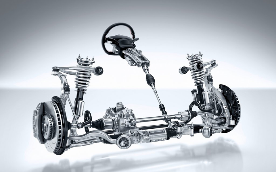
Automotive steering forms the basis of any vehicle’s motion control. It comprises of all components, joints, and linkages required to transfer power from the engine to the wheels. The steering also controls angles of the wheels in two axes for directionality.
REQUIREMENTS OF STEERING SYSTEM
The steering system has the following requirements.
1 Excellent maneuverability When the vehicle is cornering on a narrow, twisting road, the steering system must be able to turn the front wheels sharply yet easily and smoothly.
2 Proper steering effort If nothing is done to prevent it, the steering effort will be greater when the vehicle is stopped and will decrease as the speed of the vehicle increase. Therefore, in order to obtain easier steering and a better feel of the road, the steering should be made lighter at low speeds and heavier at high speeds.
3 Smooth recovery While the vehicle is turning, the driver must hold the steering wheel firmly. After the turn is completed, however, recovery – that is, the return of the wheels to the straight-ahead position – should occur smoothly as the driver relaxes the force with which he is turning the steering wheel.
4 Minimum transmission of shock from road surface Loss of steering wheel control and transmission of kickback due to road surface roughness must not occur.
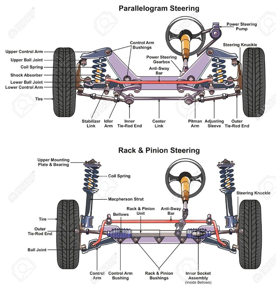
STEERING COMPONENTS
1 Steering wheel Handles the steering operation.
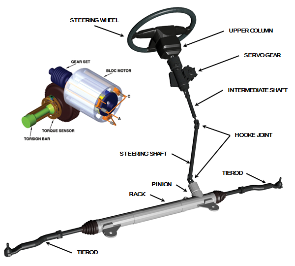
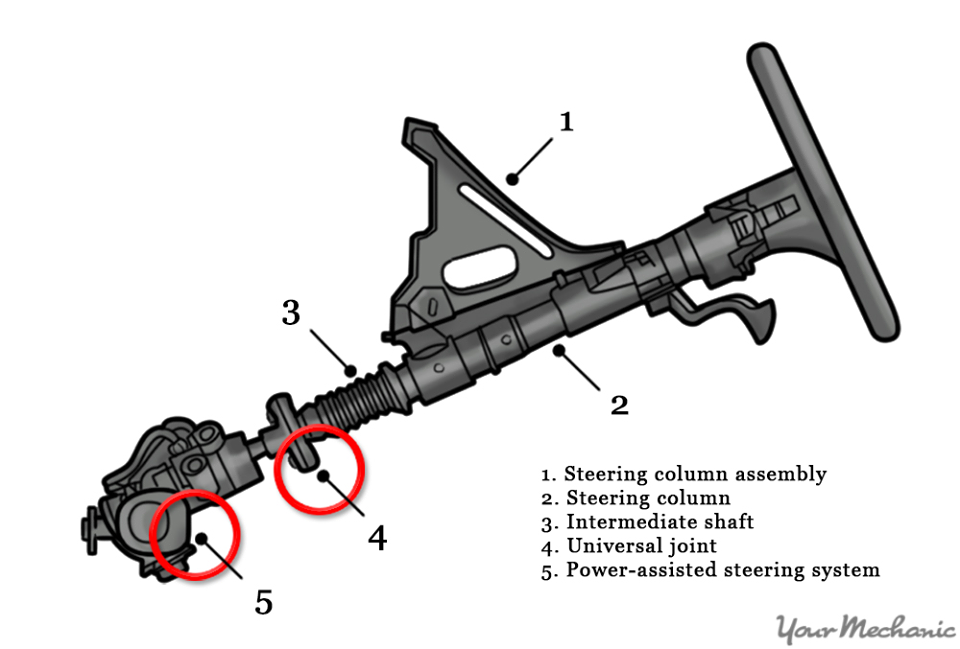
2 Steering column Joins the steering wheel and the steering gears.
3 Steering gears Convert the steering torque and rotational deflection from the steering wheel, transmit them to the wheel through the steering linkage, and make the vehicle turn.
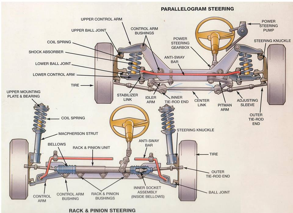
4 Steering linkage A steering linkage is a combination of the rods and arms that transmit the movement of the steering gear to the left and right front wheels.
TYPES OF STEERING SYSTEM
Also, there are two types of steering.
• Rack-and-pinion type
• Recirculating-ball type
1. Rack & Pinion
Rack-and-pinion steering is the most common type of motion control mechanism in cars, small trucks and SUVs.
Construction
1. A Rack & Pinion gear set is enclosed in a metal tube with each end of the rack pointing out from the tube.
2. A rod – tie rod or axial rod – connects to each end of the rack.
3. The pinion gear is attached to the steering shaft.
Mechanism
When you turn the steering wheel the gear will spin, moving the rack. The tie rod connects to the steering arm, which is attached to a spindle.
The purpose of a Rack & Pinion gear is to convert the circular motion of the steering wheel into the linear motion. It allows gear reduction, making it easier to turn the wheels.
The two types of rack-and-pinion steering systems:
1. End take-off
2. Centre take-off
Variable Ratio Steering
A subtype of Rack & Pinion gear steering is Variable Ratio Steering.
This steering system has a different number of tooth pitch at the center than it has at the ends.
This makes the steering less sensitive when the steering wheel is close to its center position.
And when it is turned towards the lock, the wheels become more sensitive to the circular motion of the steering wheel.
2. Re-circulating Ball / Steering Box
Re-circulating Ball Steering is the most commonly used steering system in heavy automobiles.
It runs on Parallelogram linkage, in which:
1. The Pitman & Idler arm remains parallel
2. The mechanism absorbs heavy shock loads and vibrations
Construction
1. The steering wheel is fixed to the steering shaft, which has a threaded rod at the end. The threaded rod is fixed, unlike in the Rack & Pinion type.
2. The block has gear teeth machined ON its surface.
3. The threads in the rod are filled with ball bearings.
4. These ball bearings have two functions: To reduce friction and wear in the gear; Fixing the teeth of the gear to prevent the former from breaking contact with each other when the steering wheel changes direction.
Mechanism
1. When the steering wheel is rotated, the rod turns.
2. When the wheel spins, the block moves.
3. The block moves another gear that in turn moves the Pitman’s arm.
4. The ball bearings in the threads re-circulate through the gear as it turns.
POWER STEERING
To improve driving comfort, most modern automobiles have wide, low-pressure tires which increase the tire-to-road surface contact area. As a result of this, more steering effort is required. Steering effort can be decreased by increasing the gear ratio of the steering gear. However, this will cause a larger rotary motion of the steering wheel when the vehicle is turning, making sharp turns impossible. Therefore, to keep the steering agile and, at the same time the steering effort small, some sort of a steering assist device became necessary. In other words, power steering, which had been chiefly used on larger vehicles, is now also used on compact passenger cars.
Type of power steering
There are hydraulic type and electric type power steering. Currently, hydraulic power steering is used on almost all models. The three main components of hydraulic power steering are the vane pump, control valve, and power cylinder.
Operation of hydraulic power steering

The power steering system uses the power of the engine to drive the vane pump that generates hydraulic pressure. When the steering wheel is turned, an oil circuit is switched at the control valve. As oil pressure is applied to the power piston in the power cylinder, the power needed to operate the steering wheel is reduced. It is necessary to inspect for leakage of power steering fluid periodically.
Vane Pump
Power steering is a type of hydraulic device requiring very high pressure. It uses the power of the engine to drive the vane pump uses that generates this hydraulic pressure. Vanes are used in this pump, so this name is used for this type of power steering.
STEERING MECHANISMS
1. TELESCOPIC MECHANISM
The telescopic steering mechanism allows forward or backward adjustment of the steering wheel position to suit the driver’s posture.
Construction
The telescopic mechanism consists of the sliding shaft tube, two wedge locks, stopper bolt, telescopic lever, etc.
Operation
The wedge locks move together with the operation of the telescopic lever. When the telescopic lever is in the lock position, the telescopic lever presses the wedge locks against the sliding shaft tube, locking the sliding shaft tube. On the other hand, when the telescopic lever is moved to the free position, a gap is created between the wedge locks and the sliding shaft tube and the steering column can be adjusted in the forward or backward direction.
2. TILT STEERING MECHANISM
The tilt steering mechanism allows selection of the steering wheel position (in the vertical direction) to match the driver’s driving posture. The tilt steering mechanisms are classified into the upper fulcrum type and the lower fulcrum type. Here, the lower fulcrum type is explained.
Construction
The tilt steering mechanism consists of a pair of tilt steering stoppers, tilt lock bolt, breakaway bracket, tilt lever, etc.
Operation
The tilt steering stoppers turn together with the operation of the tilt lever. When the tilt lever is in the lock position, the peaks of the tilt steering stoppers are lifted up and the stoppers push against the breakaway bracket and tilt attachment, locking the breakaway bracket and tilt attachment. On the other hand, when the tilt lever is moved to the free position, the height difference on the tilt steering stoppers is eliminated, and the steering column can be adjusted in the vertical direction.
Buenísimo el articulo. Reciba un cordial saludo.
Saludos