Vehículos Híbridos/Eléctricos funcionamiento , tipos y diseño de sistema

No photo description available.

HEVs are vehicles propelled by more than one power source such as an engine and electric motor. They are classified by type and level. The advantages of HEVs are improved fuel economy, efficiency, and reduced emissions. The disadvantage of HEVs is cost. The cost aspect may be offset in years to come due to higher gas prices and improved HEV technologies. For more information on types and levels of HEVs, visit their respective pages in the menu on the left.

Image may contain: text

Hybrid electric vehicles are powered by an internal combustion engine and an electric motor, which uses energy stored in batteries. A hybrid electric vehicle cannot be plugged in to charge the battery. Instead, the battery is charged through regenerative braking and by the internal combustion engine. The extra power provided by the electric motor can potentially allow for a smaller engine. The battery can also power auxiliary loads like sound systems and headlights, and reduce engine idling when stopped. Together, these features result in better fuel economy without sacrificing performance.

COMPONENTS OF A HYBRID ELECTRIC CAR

Battery (auxiliary):
In an electric drive vehicle, the auxiliary battery provides electricity to start the car before the traction battery is engaged and also powers vehicle accessories.

Image may contain: text

DC/DC converter:
This device converts higher-voltage DC power from the traction battery pack to the lower-voltage DC power needed to run vehicle accessories and recharge the auxiliary battery.

Electric generator:
It generates electricity from the rotating wheels while braking, transferring that energy back to the traction battery pack. Some vehicles use motor generators that perform both the drive and regeneration functions.

Electric traction motor:
Using power from the traction battery pack, this motor drives the vehicle’s wheels. Some vehicles use motor generators that perform both the drive and regeneration functions.

Exhaust system:
The exhaust system channels the exhaust gases from the engine out through the tailpipe.

Fuel filler:
This is a filler or «nozzle» used to add fuel to the tank.

Image may contain: car

Fuel tank (gasoline):
This tank stores gasoline on board the vehicle until it’s needed by the engine.

Internal combustion engine (spark-ignited):
In this configuration, fuel is injected into either the intake manifold or the combustion chamber, where it is combined with air, and the air/fuel mix is ignited by the spark from a spark plug.

Power electronics controller:
This unit manages the flow of electrical energy delivered by the traction battery, controlling the speed of the electric traction motor and the torque it produces.

Thermal system (cooling):
This system maintains a proper operating temperature range of the engine, electric motor, power electronics, and other components.

Traction battery pack:
Stores electricity for use by the electric traction motor.

Transmission:
The transmission transfers mechanical power from the engine and/or electric traction motor to drive the wheels.

FUEL-EFFICIENT SYSTEM DESIGN

HEVs can be either mild or full hybrids, and full hybrids can be designed in series or parallel configurations.

• Mild hybrids—also called micro hybrids—use a battery and electric motor to help power the vehicle and can allow the engine to shut off when the vehicle stops (such as at traffic lights or in stop-and-go traffic), further improving fuel economy. Mild hybrid systems cannot power the vehicle using electricity alone. These vehicles generally cost less than full hybrids but provide less fuel economy benefits than full hybrids.

• Full hybrids have larger batteries and more powerful electric motors, which can power the vehicle for short distances and at low speeds. These vehicles cost more than mild hybrids but provide better fuel economy benefits.

ENERGY FLOW DIAGRAMS AND DESCRIPTIONS

1. Series (Extended-Range) Hybrid

A series hybrid is like a battery electric vehicle (BEV) in design. Here, the combustion engine drives an electric generator instead of directly driving the wheels. The generator both charges a battery and powers an electric motor that moves the vehicle. When large amounts of power are required, the motor draws electricity from both the battery and the generator. Series hybrids may also be referred to as extended-range electric vehicles (EREVs) or range-extended electric vehicles (REEVs) since the gas engine only generates electricity to be used by the electric motor and never directly drives the wheels. Modern examples include the Cadillac ELR, Chevrolet Volt, and Fisker Karma.

2. Parallel Hybrid

A parallel hybrid is propelled by both an internal combustion engine (ICE) and an electric motor connected to a mechanical transmission. Power distribution between the engine and the motor is varied so both run in their optimum operating region as much as possible. There is no separate generator in a parallel hybrid. Whenever the generator’s operation is needed, the motor functions as a generator. In a parallel mild hybrid, the vehicle can never drive in pure electric mode. The electric motor turns on only when a boost is needed.

3. Series-Parallel Hybrid

The vehicle can be powered by the gasoline engine working alone, the electric motor by itself, or by both energy converters working together. Power distribution between the engine and motor is designed so that the engine can run in its optimum operating range as much as possible.

Most hybrids use several advanced technologies:

Regenerative Braking. Regenerative braking recaptures energy normally lost during coasting or braking. It uses the forward motion of the wheels to turn the motor. This generates electricity and helps slow the vehicle.

Electric Motor Drive/Assist. The electric motor provides power to assist the engine in accelerating, passing, or hill climbing. This allows a smaller, more-efficient engine to be used. In some hybrids, the electric motor alone propels the vehicle at low speeds, where gasoline engines are least efficient.

Automatic Start/Stop. Automatically shuts off the engine when the vehicle comes to a stop and restarts it when the accelerator is pressed. This reduces wasted energy from idling.

ADVANTAGES & DISADVANTAGES OF HYBRID CARS

ADVANTAGES OF HYBRID CARS

Switching to a hybrid car has many advantages, a few of which we have highlighted below:
1. Environmentally Friendly
2. Economical
3. Less Fossil Fuel Dependent
4. Regenerative Braking System
5. Light Build
6. Higher Resale Value

DISADVANTAGES OF A HYBRID CAR

1. Less Power
2. Expensive to Purchase
3. Poorer Handling
4. High Maintenance Cost
5. High Voltage Batteries

Automotive World

Para qué sirve la metrología dimensional en la Industria Automotriz ?

La medición es la manera de determinar tamaños, cantidad, extensiones. Tiene como objetivo conocer las dimensiones exactas de las piezas y facilitar su inspección ágil, sujeta a requerimientos y especificaciones ingenieriles para su fabricación.

Es la manera de describir un objeto mediante valores numéricos es por ello que se desarrollo la Meteorología en la industria que es básicamente una materia dedicada al estudio de la medición , la meteorología dimensional es la conceptualización de las propiedades que resultan mediante unidades de longitud como es la distancia

En la industria la metrología se ha vuelto parte clave y fundamental para el control de calidad de los producto es decir, de está depende si el producto que se está fabricando puede ser vendido o no, ya que como mencionamos en metrología se miden ya específicamente en la industria, espesores, profundidades, pasos, radios, soldadura, longitudes entre muchas otras variables más que son delimitadas por la especificación de un producto para venta especifica o para venta en publico,

En plantas ensambladoras se hace una muestra de lo que se está fabricando con el fin de conocer si se esta fabricando correctamente y si esta teniendo las especificaciones de tolerancia correctas y de aquí determinar si existe algún problema causado por, herramientas de fabricación(desgaste de la herramienta y que genere que estén fuera de rango de trabajo) mano de obra humana entre otros factores, así como malos cálculos o materia prima defectuosa

Ya que conoces un poco más de está importante ciencia añadiremos material para que profundices más en estos temas y conozcas los métodos de medición así como las herramientas para poder lograr dicho objetivo tales como, micrómetros, reglas, comparadores ópticos, pies de rey entre otros

Manual del estudiante Starret DESCARGA AQUI :

Metrología Dimensional DESCARGA AQUI:

Para qué sirve la Simulación en la industria Automotriz?

La simulación en el mundo industrial en especial en el sector automotriz es una pieza clave fundamental para el desarrollo de productos, esto lo logran gracias a un modelo matemático desarrollado por los ingenieros e investigadores de las armadoras esto es parte del desarrollo de la industria 4.0

La simulación se basa como ya se menciono en modelos matemáticos que son comparados con los modelos que indica el ordenador o PC mediante un software, en donde hay muchas variables que se definen para poder dar una aproximación de la realidad estas variables van desde las mas fundamentales tales como distancias, tiempos, gravedad, y las mas avanzadas tales como campo magnético, radiación, entre otras muchas mas

La simulación tiene como objetivo predecir fallos y posibles desplazamientos para optimizar la calidad del producto que están ofreciendo o la forma en que se va a trabajar, este tipo de simulaciones es de suma importancia ya que ahorra millones de dolares en pruebas y error así como una optimizacion del tiempo en realizar estas pruebas

La simulación en la industria automotriz incluye desde un desplazamiento, la fatiga que pudiera ocurrir en un elemento , y hasta simulación de manufactura de proceso de fabricación de las mismas piezas tal como se muestra en el siguiente ejemplo que nos muestra la trayectoria de la herramienta para el desbastado de la materia prima para llegar al resultado de la pieza deseada por el mecanismo y/o cliente

También la podemos encontrar en procesos como la inyección de plásticos , aquí es muy importante hacer una simulación ya que de los resultados obtenidos se fabrica un molde de inyección con sus respectivas cavidades de llenado, de enfriamiento entre otras, con el fin de obtener el mejor resultado de la pieza a a inyectar

Es importante destacar que las herramientas CAE (Computer Aided Engineering ) son pieza clave para el desarrollo y perfección de productos con el fin de evitar gastos en reparaciones o campañas de reparación como llega a suceder con las armadoras cuando un producto tiene alguna deficiencia optimizan sus modelos para dar soluciones a los clientes de manera eficaz

Ejemplo de simulación extraída de MSC Software

En resumen si tu deseas aprender la simulación es muy importante que sepas que la simulación puede llegar a salvar vidas, y para ello requiere un amplio portafolio de conocimiento en materias como estática, termodinámica, transferencia de calor, dinámica, elemento finito, propiedades de los materiales, calculo integral, vectorial y diferencial así como ecuaciones diferenciales entre otras mas y un amplio conocimiento en modelado 3D

Actualmente es importante conocer estas herramientas ya que si deseamos desarrollar un proyecto propio y realizamos una simulación garantizamos que va a funcionar como lo planeado y será un atractivo plan para nuestros clientes ya que le estamos garantizando un trabajo optimo que en la realidad va a tener la función especifica que estamos vendiendo tal y como sucede en la industria

Qué son los engranes y cuál es su función y cómo se diseñan?

Resultado de imagen para engranajes catia

La función de un engrane radica en la transmisión de movimiento ya sea rotatorio o reciprocante de una maquinaria a otra y donde requiere reducir o aumentar las revoluciones de un eje

Los engranes se caracterizan por ser cilíndricos o conos rodantes que poseen dientes en la superficie de contacto para que se genere un movimiento positivo

Los engranes son los mas eficaces debido a su durabilidad y resistencia de todos los transmisores mecánicos. Es por eso que se utilizan engranes en lugar de bandas o cadenas en transmisiones automotrices a excepción de la transmisión CVT que se acciona por una correa o como las bicicletas

Image may contain: text
No photo description available.
Image may contain: text
No photo description available.

Material de descarga: DESCARGA AQUI ⬇⬇⬇

Qué es y como funciona el principio de Ackerman?

Cómo funciona?

El principio de Ackerman enuncia que cuando un vehículo gira en una curva, los ejes de todas las ruedas deben concurrir en un punto, el centro instantáneo de rotación. La mangueta de la rueda interior debe de girar un ángulo mayor que la de la rueda exterior, luego se precisa una divergencia de las ruedas delanteras cuando se toman las curvas para evitar el desgaste de las cubiertas y evitar el deslizamiento. Con el mecanismo, anteriormente mencionado, conseguimos una geometría óptima para la dirección. Para seguir este principio se hace que el ángulo de giro de la rueda interior sea mayor que la exterior, es decir, como se muestra en la figura.

Cuando un vehículo describe una curva, todas las ruedas deben girar entorno al mismo centro instantáneo de rotación, permitiendo un mejor control y minimizando el desgaste de las ruedas. Cada una de las ruedas directrices debe por ello describir un arco de diferente radio, siendo el radio del arco que describe la rueda exterior mayor que el de la interior.

Se denomina centro instantáneo de rotación al punto respecto al cual un sólido está girando en un instante. La línea que une el centro instantáneo de rotación y un punto cualquiera del sólido es perpendicular a la velocidad de dicho punto.

Según Ackermann, el ángulo que forma la rueda exterior con la extensión del eje trasero (α) ha de ser menor que el formado por la interior (β).

244bbcw

Si un vehículo se diseña sin tener en cuenta el principio de Ackermann y las dos ruedas delanteras giran el mismo ángulo, no estarán girando con respecto al mismo punto. Esto genera inestabilidad y desgaste excesivo del neumático.

Untitled

En caso de aplicarse el principio de Ackermann, la rueda interior girará con mayor ángulo de forma que el centro instantáneo de rotación sea el mismo para todas las ruedas.

Para conseguir este efecto, las bieletas de dirección formarán cierto ángulo con el eje longitudinal, como se describe en la imagen inferior.

Jeantaud

El cálculo de Ackermann se basa en la fórmula:

Via/Batalla = cotg(α) – cotg(β)

La formula para calcular Ackermann se obtiene despejando α de la anterior, de modo que:

Ackermann = arctan ( batalla / (batalla/tan(β) – via) )

Porcentaje = 100 · ( α / Ackermann )

Un 100% Ackerman significa que las prolongaciones de las bieletas se cortan en el centro del eje trasero. En caso de que el porcentaje sea superior a 100, éstas se cortarán por delante del eje trasero; y detrás si es inferior.

Todo esto está muy bien en teoría, pero en la práctica los neumáticos se deforman. A esta deformación se la conoce como ángulo de deriva y es la diferencia entre el ángulo de giro y el ángulo que realmente adquiere la superficie de contacto del neumático debido a las fuerzas que se ejercen sobre él.

En los vehículos modernos no se utiliza un sistema de dirección Ackermann puro. Debido a la transferencia lateral de masas, las ruedas en las que la carga es menor, requieren menos ángulo de deriva para llegar a su límite de adherencia.

Para conseguir los efectos deseados en la geometría se debe introducir el concepto de convergencia.

True-Ackermann-Toe-In

Si la convergencia es positiva, las dos ruedas directrices tendrán cierta convergencia hacia el centro de las trayectorias, es decir, la rueda interior tratará de describir una circunferencia ligeramente mayor y la exterior una circunferencia ligeramente menor a la que está siguiendo. Con esta geometría se reduce el ángulo de deriva de la rueda interior y se aumenta el de la exterior.

En caso de que la convergencia sea negativa la rueda interior tratará de describir una circunferencia menor a la que está siguiendo y la exterior una circunferencia mayor. Con esta geometría el ángulo de deriva de la rueda interior aumenta, reduciéndose el de la rueda exterior.

Qué son las bandas y cual es su función en el motor?

Las bandas en un motor es muy importante ya que estas se encargan de sincronizar y/o dar movimiento , actualmente muchas bandas ya son reemplazadas por cadenas de distribución (sincronización del motor) , pero en las bandas de accesorios se mantienen en pie , las bandas de accesorios conectan , compresor de aire acondicionador , polea de cigüeñal , tensores , bombas hidráulicas , bombas de agua (en varios autos la cadena de distribución se conecta con esta bomba) , alternador , poleas locas , generalmente están fabricadas de caucho y si se encuentran agrietadas o desgastadas irregularmente hay que reemplazar por una nueva , el intervalo puede variar dependiendo el fabricante por eso es muy importante verificar el kilometraje de estas en el manual de usuario y hacer inspecciones visuales del estado de esta misma , la ruptura de estas bandas podrían causar daños fatales en el motor , sistema de carga , sistema de dirección , sistema de enfriamiento ,inclusive hasta supercargadores

Existen diferentes disposiciones de bandas en V, lisas, dentadas, sin embargo su funcionamiento de impulsar movimiento es el mismo y es importante tener en cuenta de que no hayan grietas ni rupturas en estas que puedan ocasionar daños mecanicos en el motor

Qué es y como funciona el aquaplaning en los neumáticos?

Resultado de imagen para aquaplaning

Aquaplaning
El aquaplaning se produce cuando el agua situada entre el neumático y la superficie de la carretera no puede ser desplazada. El neumático pierde el contacto con el suelo y su poder de tracción, llegando a no responder a los giros del volante, a los frenos, al acelerador, etc…Como resultado, se pierde el control del vehículo. Esta situación es potencialmente muy peligrosa.

¿Cómo evitar o reducir el aquaplaning?
Comprueba tus neumáticos y la presión regularmente. Una presión insuficiente aumenta significativamente el riesgo de aquaplaning. Si la presión del neumático es un 30% inferior a la presión recomendada existe un riesgo mucho mayor de aquaplaning.
-Comprueba el desgaste de los neumáticos y la profundidad de la escultura. Cuanto mayor sea la profundidad del dibujo, más cantidad de agua puede evacuar el neumático, lo que reduce el riesgo de aquaplaning.
-Reduce tu velocidad, sobre todo cuando te aproximes a un charco.

Resultado de imagen para aquaplaning

¿Qué provoca el aquaplaning?

En el rodaje sobre suelo mojado, delante del neumático se forma una cuña de agua que el neumático va desplazando y evacuando, ejerciendo una presión sobre ésta.
El aquaplaning se produce cuando la presión de la cuña de agua es superior a la presión del neumático sobre el área de contacto, el neumático se sube sobre la capa de agua perdiendo el contacto con el suelo. Esta pérdida de contacto del neumático con el suelo hace que el neumático pierda su poder de tracción y por lo tanto patine sobre la capa de agua, no respondiendo a los movimientos del volante, a los frenos, al acelerador, etc. Es entonces cuando se pierde el control del vehículo. .
Los principales factores que ayudan y favorecen el aquaplaning son la velocidad, la altura de la capa de agua, la altura de dibujo del neumático y la presión de inflado del mismo.
Por todas estas razones, en mojado, es PRIMORDIAL reducir la velocidad de circulación.

Relación entre dibujo y agua

Afortunadamente, la mayoría de los incidentes de aquaplaning pueden evitarse o minimizarse con el ranurado de la escultura y la forma de la zona de contacto. Sin embargo, a medida que la escultura se desgasta, merma su capacidad para resistir el aquaplaning. Cuanto más alta sea la capa de agua, antes entraremos en aquaplaning perdiendo el poder de tracción del neumático.

Sistema antisurf: agarre óptimo en mojado

Cuando hay una cierta altura de agua en la carretera, la mayoría de los neumáticos sufren aquaplaning. Ahora tienes la posibilidad de atravesar «charcos» y mantener el agarre óptimo gracias a tecnologías Michelin como el sistema antisurf. Presente en neumáticos como MICHELIN Pilot Sport 3, proporciona unas prestaciones óptimas en mojado. El diseño especial del hombro curvado del Pilot Sport 3 le permite atravesar la capa de agua retrasando la formación de aquaplaning sin reducir el área total de contacto con la carretera.

Información tomada de la página oficial de Michelin

Qué es el sistema BMW Condition Based Servicing (CBS)?

BMW Condition Based Servicing (CBS) es un moderno sistema de monitoreo del estado de mantenimiento del vehículo mediante conteo de kilometros y días, que sirve como referencia especifica para determinar el mantenimiento que se le deberá ejecutar a la unidad BMW, este sistema se basa como ya mencionamos con kilometros recorridos así como días transcurridos para evitar averías y conservar el vehículo en optimas condiciones de uso.

Estas condiciones las maneja mediante una linea de datos en tablero el cual nos indicará el tiempo restante y los kilómetros restantes antes de su mantenimiento, y en el caso de que rebase estos dos parámetros nos va a mostrar un mensaje en pantalla advirtiéndonos que es necesario inspección o que un elemento esta fuera de especificación.

Este sistema básicamente está programado y hermanado con sensores de nivel, sensores de velocidad, así como sensores de presión , entre otros para monitorear el estado de los componentes de recambio principales del automóvil.

Los monitores CBS en BMW es una herramienta indispensable para el técnico así como para el usuario ya que en ella vamos a encontrar información de valor muy importante tales como:

  • Mantenimiento requerido
  • Nivel de aceite
  • Fechas de inspección
  • Estado del aceite de motor
  • Estado del liquido refrigerante
  • Estado del liquido de frenos
  • Estado de las pastillas de freno traseras y delanteras
  • Examen de estado de emisiones
  • Inflado de llantas
Imagen relacionada

Esta información es importante ya que en ella manejan fechas, estados y niveles que a partir de esa información actualizada del vehículo se le podría determinar al cliente un posible mantenimiento antes de tener una avería en el vehículo lo que podría generar costos así como una inversión de tiempo en centro de servicio.

Cada vez que hagamos un mantenimiento es de suma importancia realizar un nuevo aprendizaje o reset , ya que de aquí se parte de cero en donde el CBS cuenta los kilómetros nuevos recorridos así como los días y de no hacerlo hay un descontrol con las piezas o líquidos reemplazados y se pierde el cambio exacto de estos pudiendo provocar daños de pequeños a graves.

Las herramientas de diagnóstico modernas y de nivel 3 por lo general pueden realizar este tipo de reseteos ya que actualmente lo único que se puede revisar manualmente es el nivel del aceite tal y como de muestra en el siguiente vídeo.

El reseteo de servicios se realiza entrando directamente a CBS o a reseteo de Servicios con nuestra herramienta de diagnóstico para realizar el aprendizaje de fecha y kilometraje del servicio que hayamos realizado tal es el caso del siguiente vídeo.

Cuáles son las fallas que puede presentar un ventilador automotriz?

Problemas comunes del #ventilador del radiador:

Imagen relacionada

El ventilador del radiador es un componente fundamental en el motor, éste se activa a través de un bulbo o sensor de temperatura que se encuentra en el radiador apenas llega a 90 grados centígrados. El motor comienza el ciclo de enfriamiento y una vez que llega a 70 grados se apaga.

La única ventaja de tener problemas en dicho dispositivo, es lo fácil que se detecta cuando está fallando.

Imagen relacionada

Problema en los sensores: Esto se detecta cuando se apaga el auto y el ventilador sigue trabajando. No representa daño para el auto, pero de un momento a otro puede presentar fallas en el ventilador.


Fusible fundido: Se presenta cuando el auto posee dos ventiladores y ninguno de ellos funciona.


Motor quemado: Cuando solo uno de los dos ventiladores funciona, seguramente el motor de uno de ellos se quemó, o existe una mala conexión.


Termostato: Si los ventiladores no funcionan, pero el medidor de temperatura en el tablero es normal, el problema radica en el termostato. En algunos casos el termostato se pega o recuesta con el resorte. Para solucionar el problema debe cambiar el termostato.


Bajo voltaje: Cuando no existe suficiente carga, los ventiladores no reciben la fuerza necesaria para trabaja

Reparación:

En muchos casos principalmente en autos modernos la reparación consta de revisar el modulo de control del moto ventilador, cuando este tiene juego o los carbones presentan desgaste comienza a marcar códigos de error de PCM, y por lo general hay dos tipos de reparaciones una es el reemplazo del moto ventilador junto con las aspas. La segunda reparación que se le pudiera dar es el de reemplazar los carbones para darle una segunda oportunidad a la pieza automotriz sin embargo es mas confiable la primera ya que se haya comprobado correctamente que no sirve

Cuando se instala correctamente, lo que se debe revisar también en conjunto es su fusible y revelador y si es posible reemplazarlos al mismo tiempo esto para garantizar que la reparación hecha va a estar garantizada ya que por la corriente que maneja y voltaje genera también un desgaste que va en conjunto con el moto ventilador

Ya hecho los dos pasos anteriores solo queda instalar correctamente el componente y poner a trabajar el automóvil y revisar que el moto ventilador trabaje 3 veces seguidas y que se active y se desactive a la misma temperatura para garantizar que el trabajo se hizo correctamente y que la pieza instalada no tiene ningún defecto y así dejar satisfecho a nuestro cliente

Bielas que varian su longitud para conseguir mejoras de hasta el 7% en consumo

Los motores de relación de compresión variable sigue suponiendo uno de los grandes retos de la industria en lo que a beneficios ofrece y complicaciones de diseño sugiere. Variar la relación de compresión en cada uno de los cilindros permite contar con un ciclo de trabajo adaptado a cada circunstancia, permitiendo adaptar el propulsor para otorgar altas dosis de potencia o reducidos consumos de carburante.

Marcas como SAAB o Peugeot han mostrado al público prototipos que buscaban dotar a los propulsores gasolina de esta posibilidad de variar la relación de compresión bajo demanda, pero sus elevados costes y complejidad técnica han alejado a esta tecnología del mercado. Ingenieros de FEV han mostrado su último desarrollo donde el diseño de una biela convencional ha sido adaptado para permitir variar la relación de compresión garantizando dos estados diferentes donde encontrar máxima eficiencia y máxima entrega de prestaciones.

Relación de compresión variable

Bielas que varian su longitud para conseguir mejoras de hasta el 7% en consumo

El concepto de relación de compresión variable es uno de las grandes frentes de la industria para mejorar el motor de combustión interna

El diseño mostrado por FEV hace gala de un mecanismo que, mediante el empleo de un circuito de aceite a presión, permite modificar la altura de la cabeza del pistón respecto de la cámara de combustión. Modificando esta distancia, se consigue variar la relación de compresión entre dos valores fijos establecidos.

Uno de las claves de este diseño implementado por FEV es la búsqueda de una solución que permita un funcionamiento sin alterar lo que se podría entender como estructura clásica de un motor de combustión interna. Huelga a decir que la complejidad técnica y elevados costes son el principal enemigo de esta tecnología. De este modo, FEV ha rediseñado la clásica biela que une pistón y cigüeñal para configurarla de tal modo que permita la modificación de la alzada del pistón en el interior del cilindro.

Bielas que varian su longitud para conseguir mejoras de hasta el 7% en consumo

En un motor gasolina donde la relación de compresión estaba situada en 9,6, FEV ha instalado su sistema de relación de compresión variable permitiendo un margen de entre 8 y 13. Con esta configuración y bajo ciclo de homologación NEDC, el consumo se ha reducido en un 5,6%. A su vez, aplicando este diseño de relación de compresión variable a mecánicas muy compactas fruto del downsizing, FEV establece que la reducción en consumo podría alcanzar el 7%.

Fuente: GreenCarCongress | FEV | Diariomotor

¿Cuáles son los componentes principales y la función de las válvulas?

VALVE TRAIN: COMPONENTS, TYPES AND THEIR FUNCTION

No photo description available.

The main function of the valve train, as indicated by its name, is to control the opening and closing of the valves and, for older models, the fuel output of the injectors. Most of the heavy-duty diesel engines we work with are 4 valve engines, meaning there are four valves in each cylinder: 2 intakes and 2 exhaust. The valve train uses different components based on the type, push on or lift up from the valves, allowing air into and out from the cylinder. In the middle of all the valves is the injector, which will be pushed down on to inject fuel into the cylinder. All of the timing for this process is incredibly precise. Newer engines use electrical signals to cue the injector, rather than the mechanical valve train, which makes that process even more precise.

Most new engines have overhead cam assemblies. Other designs locate the camshaft lower in the engine and use push rods to move valve assemblies. The camshaft is rotated by a timing belt, timing chain or direct gear.

VALVE TRAIN COMPONENTS

The valve train can have many components. The following are the most common components in the valve train. Depending on the type of engine, there may be varying quantities of the parts listed below or the engine may not contain all of the parts listed.

1. Camshaft
The camshaft is a long shaft that goes through the head or the block of the engine, depending on what type of engine it is. There are lobes along the length of the shaft positioned differently. The profile of the lobes has an egg-shape to them. The dimensions of these lobes are what determines the amount of lift. The more lift, the longer the valves stay open, which allows more air into the cylinder.

2. Camshaft Followers
A cam follower is a type of bearing that follows along the lobes of a camshaft as it rotates, providing a low-resistance surface for the lobe to push up against. A follower is also called a lifter, and sometimes a tappet. There are several types of cam followers, whose configurations generally depend on how they mount to their mating part. They will be used when the cam is in the block, rather than being overhead.

No photo description available.

3. Push Rods
Pushrods are one of those parts that are not always used in a diesel engine. They will also only be used when the cam is in the block and not overhead. A push rod is a rod that pushes up on the rocker arm. It will move depending on the movement of the camshaft follower. Another job of the pushrod is to conduct oil up to the cylinder head.

4. Rocker Arms
A rocker arm is a pivoting lever that pushes on the valve stem. Rocker arms will sometimes be called rocker levers, or just rockers. Depending on the type of valve train, the rotating camshaft lobes will either push directly on the rocker arm, or on the pushrods, which will conduct the motion up to the rocker arm. In an overhead cam engine, the cam follower is built into the rocker arm in the form of a roller.

5. Rocker Shafts
Rocker shafts are simply the shafts that the rockers are on. It’s this shaft that is the pivot point for the rocker arms. The shaft also conducts oil to the various rocker arms.

6. Valve Bridges
Valve bridges are also sometimes called valve yokes. Bridges allow a single rocker to actuate multiple valves. It has a stem or bridge that sits on both valve stems, so that when the rocker is pressed down, the valve stems get pressed down as well.

7. Valves
A valve is composed of two major sections, the valve head, and the valve stem. The head of the valve is what allows air into and out of the cylinder. The stem is what gets pressed on by the rest of the valve train. At the end of the stem are grooves that keepers will fit into to hold the valve in place. Some engines have only two valves per cylinder, and some have four. The more common number in the heavy-duty diesel market is four. These are split evenly between the intake and exhaust valves.

8. Valve Springs
The camshaft creates an upward force that acts on the rocker arm, which in turn pushes the valve down. But as the cam rotates around, it does not pull the pushrod or rocker arm back with it. That’s why there is a valve spring to create force in the opposite direction and close the valve. The spring will hold the valve closed until the lobe of the camshaft comes around with a greater force and pushes it down.

9. Timing Belt:
A timing belt instead of a timing chain may be used to turn the camshafts. The inner side of the belt is designed with square (cogged) teeth which prevent the belt from slipping.

10. Belt Tensioner
The belt tensioner is a spring-loaded wheel which keeps the timing belt in tension and aligned with the cam sprocket. The smooth side of the timing belt rides over the tensioner. The tensioner applies a force on the backside of the belt. This keeps the belt in tension. Whenever the belt needs to be removed, the tensioner can be pulled away, freeing the belt.

TYPES OF VALVE TRAINS

1. OHV or Push-rod valve train

In case of OHV or push-rod systems, there are long rods which have to be pushed by the camshaft lobes to move the valve rockers, which in turn open the valves – thus the name ‘push-rod’. The long rods and the mechanical nature of the pushrod system make it heavy and it’s not compatible with engines which run at higher revolutions per minute. Now while OHV is an older design, it has its advantages in terms of simplicity of design, compact packaging and a simpler lubrication system requirement as compared to an OHC system.
The disadvantages, of a pushrod system, however, are many.
• To start with, the engines with an OHV system cannot run very high RPMs and such valve trains are suitable mostly for low engine speed applications such as heavy cruisers.
• Owing to the heavy components, the noise and friction on such systems are much more than an OHC system.
• Also, any issues with the camshaft require the entire engine to be opened up, as the camshaft sits inside the engine block, which increases the maintenance effort and cost in case of a breakdown.
• Finally, OHV engines lend their design well primarily to two-valves per cylinder layout. It’s not that there aren’t any three or four valves per cylinder engines with OHV, but that setup becomes way more complex, and OHC systems offer much more flexibility with multiple valves per cylinders.

No photo description available.

2. OHC Valve trains

To overcome the shortcomings of the pushrod valve trains, OHC valve train was developed. As the name suggests, it’s a valve train configuration where the camshaft for the engine is placed over the head of the engine, above the pistons and valves. This design allows for very direct contact between the camshaft lobes and the valves or a lifter, thus reducing mass, reducing components and allowing better engine performance as well as more flexibility with the overall engine design.

A. Single Overhead Cam/SOHC

For this variety of valve trains, there is a single camshaft for each row of engine heads. So a single cylinder OHC engine will have one camshaft. However, if it’s an engine with multiple rows, say a V6, then it will have two camshafts – one for each row of heads, or each bank. For SOHC engines, the camshaft is connected directly to the crankshaft via a timing belt or chain to ensure that the opening and closing of the valves is perfectly in sync with the various strokes of the engine for each cylinder.

Now, with SOHC, there is an option to either open or close the valves directly with a shim between the cam lobe and the valve stem, or via a rocker arm. Valves have springs which return them back to their closed position once the pressure from the camshaft lobe is off. SOHC engines are also suited better for 2 or 3 valves per cylinder configuration. Not that a SOHC valve train cannot run on a 4 valve per cylinder layout, but the whole set-up then becomes too complex for the design of rocker arms and lobes and it’s generally considered better to employ a DOHC valve train is such scenarios.

B. Double Overhead Cam/DOHC

DOHC or dual overhead camshaft design includes two camshafts for every row of cylinder heads. Talking about the example we took for SOHC, a DOHC setup for a single-cylinder engine will have two camshafts. However, if it’s a V6, it will have 4 camshafts, two for each row of engine heads, or banks. The primary advantage of such a setup is that it allows manufacturers to have a well-engineered answer to handling a 4-valves per cylinder. Generally, one of the camshafts handles the intake valves, while the second one handles the exhaust valves. The 4-valve per cylinder setup allows for better breathing for the engine, and better performance in most cases, making DOHC a choice for engines that need to rev higher. A DOHC setup also allows for putting the spark plug bang in the middle of the cylinder head, which facilitates better combustion, and enhances performance, and fuel efficiency of the engine. With SOHC, such a setup is not possible for 4-valves per head, as it has to sit in the middle of the cylinder head so as to operate both intake and exhaust valves. As mentioned before, though, SOHC engines too can handle four valves per cylinder, and while the construction of such valve trains is complex, it’s desirable in some cases. DOHC brings along the extra weight of the additional cam, though by allowing the positioning of the spark plug in the middle of the cylinder head it also enhances optimum combustion of fuel. In a nutshell, DOHC is more suited for high-performance engines which need to rev higher and perform in the higher rev range. SOHC systems have somewhat better lower end torque though.

Finally, a DOHC system, with its more fine-grained control over valves is more suitable to implement variable valve timing for engines. Such systems utilize variable camshaft profiles for different engine speeds to enhance performance across the entire rev band. The control over the speed and position of valves opening and closing is better in case of DOHC, and in today’s electronics driven world, great benefits can be extracted using that fact. DOHC valve train is more expensive than SOHV though and coupled with its suitability for 4 valves per cylinder, it makes it feasible to employ that setup only on automobiles above a certain price point. For applications where everyday usability, low and mid-range torque, simplicity of design, easy construction and cost are important factors, SOHC system works well.

Automotive World

¿Qué es el Dámper en el motor del automóvil?

Resultado de imagen para damper automotriz

El dámper no es más que una polea situada en un extremo del cigüeñal. De hecho, técnicamente lo correcto es llamarla polea del cigüeñal, aunque comúnmente se la conozca como “dámper” o “polea dámper”.

Su función es parecida a la del volante bimasa, sirve para amortiguar las vibraciones del cigüeñal provocadas por la serie de explosiones que mueven los pistones

Si la polea dámper de nuestro coche se estropea lo primero que notaremos serán más vibraciones y ruidos provenientes del motor, sobre todo al ralentí. El cigüeñal sufrirá más y debido a las torsiones que el dámper no amortiguaría, podría llegar a romperse preparando una carísima avería que podría acabar mandado el coche al desguace.

Una polea dámper en mal estado también puede provocar que se salte la distribución, se rompa la correa, la bomba de la dirección o deteriore el funcionamiento del compresor de aire acondicionado. En cualquier caso, una avería cara de reparar.

Es un elemento muy sencillo, pero conviene revisarlo periódicamente por el bien de la vida útil de nuestro motor.

Cuáles son los grados mecánicos que influyen en los neumáticos?

No photo description available.

Todos los vehículos de transporte vienen con una convergencia positiva para que al estar en movimiento, las ruedas tiendan a quedar paralelas. Esto ocurre porque el eje delantero, al ser empujado, permite una abertura de las ruedas, dentro de los límites de operación de los componentes de la dirección. Por lo tanto si las terminales estuvieren flojas más de lo normal tenderán a abrirse más, generando convergencia negativa.

Si el desgaste del neumático aparece a partir del hombro externo, indicará convergencia positiva en exceso.

La DIVERGENCIA significa que los bordes traseros de las llantas, ya sean del eje trasero o delantero, estarán más cerca entre sí que los bordes delanteros. La divergencia se usa comúnmente en autos de tracción delantera para contrarrestar la tendencia a converger mientras se conduce a velocidades altas. Alguna divergencia es necesaria para que los automóviles viren.

Si se tienen averías en los brazos auxiliares, estarán afectadas la convergencia y la divergencia en curvas, ambas produciendo el mismo síntoma de desgaste en los neumáticos (desgaste escamado a partir de los hombros internos, en dirección al centro de la banda de rodamiento). Esto ocurrirá porque las ruedas se abrirán más de lo necesario.

El CAMBER es el ángulo que forman por una parte una línea imaginaria de la rueda con una línea vertical y perpendicular al piso. El camber puede ser hacia dentro (camber negativo) o hacia fuera (camber positivo).

Todos los vehículos de transporte vienen con camber positivo, pues cuando el vehículo recibe su carga y es puesto en movimiento, la tendencia de las ruedas es de abrirse en la parte inferior.

Cuando el eje se desvía por sobrecarga, el camber queda negativo y el desgaste de los neumáticos se producirá a partir de los hombros internos, esto es porque las ruedas habrán quedado muy abiertas en la parte inferior.

El desgaste por camber incorrecto se acentúa en los hombros del neumático, no solo por la alteración de la distribución de peso, si no principalmente por generar dos diámetros diferentes dirigidos por el radio inferior, girando en torno al mismo eje.

Cuál es la función principal del clutch en la transmisión manual?

CLUTCH: FUNCTION, WORKING AND CLASSIFICATIONS

No photo description available.

The clutch is a mechanical device, which is used to connect a driving shaft to driven shaft so that they can be engaged and disengaged at the will of the operator. They used to start and stop a part of a system without stopping remaining parts of the power transmission system. They are used mostly in automobiles. The clutch allows to insert a gear system (gearbox) between engine and wheels, facilitate gear changing when the engine is running. Other applications of clutch: Torque limiting clutch in the electric screwdriver, bicycles pedal ratcheting.

Function of the Clutch

1. Function of transmitting the torque from the engine to the drivetrain.
2. Smoothly deliver the power from the engine to enable smooth vehicle movement.
3. Perform quietly and to reduce drive-related vibration.
4. Protect the drivetrain when given the inappropriate use. Given the situation, the Exedy clutch will fail when giventhe inappropriate use inturn to protect the rest of the drivetrain, similar to the function of an electric fuse.

Requirements of a good clutch

1. The clutch should be able to transmit 1.25 to 1.50 times the maximum engine torque.
2. The clutch material should have good coefficient of function.
3. Lot of heat is generated due to the relative motion between the flywheel, pressure plate and clutch plate during clutch operation. This heat needs to be quickly dissipated, otherwise high temperature can damage clutch components.
4. The clutch should have low moment of inertia, otherwise the clutch will keep spinning at high speed even during gear changing.
5. Vibration and Jerk absorption. The clutch should be able to take up sudden jerks encountered when the clutch plate comes in contact with the rotating flywheel.
6. The clutch should be dynamically balanced or it will lead to vibrations at high speeds.
7. The operation of the clutch pedal should be easy for the operator and not tiresome, especially for operating for long durations.

Clutch Facing Material

While selecting material for clutch facing, it is to be kept in mind that the material should have high coefficient of friction, low heat generation and quick dissipation of generated heat. These qualities are counter to each other. Hence a tradeoff has to be reached. Most common materials that can be used are as follows:
* Leather -Coefficient of friction of dry leather on iron is 0.27
* Cork -Coefficient of friction on dry steel is 0.32
* Fabric -Coefficient of friction on dry steel is 0.4, but these cannot be used at high temperature.
* Asbestos -Coefficient of friction on dry steel is 0.2, has good anti-heat properties, but is harmful for human health.
* Ferodo Material -This material is based on asbestos and has a coefficient of friction 0.35.

HOW CLUTCH WORKS

No photo description available.

It transmits engine power to the gearbox, and allows transmission to be interrupted while a gear is selected to move off from a stationary position, or when gears are changed while the car is moving.

Most cars use a friction clutch operated either by fluid (hydraulic) or, more commonly, by a cable.

When a car is moving under power, the clutch is engaged. A pressure plate bolted to the flywheel exerts constant force, by means of a diaphragm spring, on the driven plate.

Earlier cars have a series of coil springs at the back of the pressure plate, instead of a diaphragm spring.

The driven (or friction) plate runs on a splined input shaft, through which the power is transmitted to the gearbox. The plate has friction linings, similar to brake linings, on both its faces. This allows the drive to be taken up smoothly when the clutch is engaged.

When the clutch is disengaged (pedal depressed), an arm pushes a release bearing against the centre of the diaphragm spring which releases the clamping pressure.

The outer part of the pressure plate, which has a large friction surface, then no longer clamps the driven plate to the flywheel, so the transmission of power is interrupted and gears can be changed.
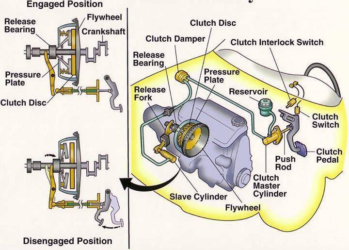
Clutch engaged
The diaphragm spring is holding the driven plate.

Clutch disengaged
The release bearing has depressed the diaphragm spring.

When the clutch pedal is released, the thrust bearing is withdrawn and the diaphragm-spring load once again clamps the driven plate to the flywheel to resume the transmission of power.

Some cars have a hydraulically operated clutch. Pressure on the clutch pedal inside the car activates a piston in a master cylinder, which transmits the pressure through a fluid-filled pipe to a slave cylinder mounted on the clutch housing.

The slave-cylinder piston is connected to the clutch release arm.

CLUTCH TYPES

No photo description available.

These may classified as follow:

According to the method of transmitting torque:

1. Positive clutch (Dog clutch):
In the positive clutch, grooves are cut either into the driving member or into the driven member and some extracted parts are situated into both driving and driven member. When the driver releases clutch pedal then these extracted parts insert into grooves and both driving and driven shaft starts revolve together. When he push the clutch pedal these extracted parts come out from grooves and the engine shaft revolve itself without revolving transmission shaft.

Application of positive clutch

They have very limited use. However, they have some application where the synchronous drive is required.

Advantages and disadvantages of positive clutch

Advantages
1. They do not slip.
2. They can transmit large torque.
3. Develop no heat during engagement and disengagement because of rigid interlocking (no friction).

Disadvantages
1. Engagement of clutch cannot be possible at high speed.
2. While starting some relative motion may be required to engage.

2. Friction clutch:
In this types of clutches, friction force is used to engage and disengage the clutch. A friction plate is inserted between the driving member and the driven member of the clutch. When the driver releases the clutch pedal, the driven member and driving member of clutch, comes in contact with each other. A friction force works between these two parts. So when the driving member revolves, it makes revolve the driven member of clutch and the clutch is in engage position. This type of clutch is subdivided into four types according to the design of the clutch.

Advantages of friction clutch

No photo description available.

1. Smooth engagement and minimum shock during the engagement.
2. Friction clutch can be engaged and disengaged when the machine is running since they
have no jaw or teeth.
3. Easy to operate.
4. They are capable of transmitting partial power.
5. Friction clutch can act as a safety device. They slip when the torque exceeds a safe value,
thus safeguards the machine.
6. Frequent engagement and disengagement is possible

Requirement of good friction clutch

1. The following are considered during the design of the friction clutch.
2. The coecient of friction of contact surface should be high enough to hold the load with a minimum amount of axial force. It should not require an external force to carry the burden.
3. The moving parts of the clutch should be lightweight to minimize the inertia load at high speed.
4. Heat generated at contacting surface should dissipate rapidly.
5. It should have provision for taking up the wear of contact.
6. Guard the projecting parts by covering and provide a provision for easy repair.

Requirements of material used for friction clutch

1. The actual contact surface of the friction clutch is the friction lining. Linings are subjected to severe rubbing during a machine run. There are many factors that decide the material
for lining is viable or not. However, the lining material should have certain qualities.
2. It should have a relatively high and uniform coecient of friction under all service conditions.
3. High resistance to wear.
4. It should withstand a high compressive load.
5. It should be chemically inert, oil and moisture have no eect
on them.
6. High heat conductivity. It should rapidly dissipate the heat generated.
7. It should have excellent compactibility with cast iron facing.

A.) Cone clutch:
It is a friction type of clutch. As the name, this type of clutch consist a cone mounted on the driven member and the shape of the sides of the flywheel is also shaped as the conical. The surfaces of contact are lined with the friction lining. The cone can be engage and disengage from flywheel by the clutch pedal.

B.) Single plate clutch:
In the single plate clutch a flywheel is fixed to the engine shaft and a pressure plate is attached to the gear box shaft. This pressure plate is free to move on the spindle of the shaft. A friction plate is situated between the flywheel and pressure plate. Some springs are inserted into compressed position between these plates. When the clutch pedal releases then the pressure plate exerts a force on the friction plate due to spring action. So clutch is in engage position. When the driver pushes the clutch pedal, due to its mechanism, it serves as the disengagement of clutch.

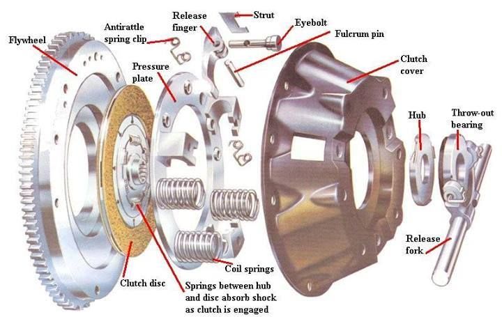
Main components of a Single Plate Axial Spring type friction clutch

1. Flywheel: It is connected to the engine crankshaft and is used to store the energy.
2. Clutch Plate: It consists of a steel disc with the centre splined. Frictional material is mounted (riveted) around the circumference of the steel disc.
3. Pressure Plate: The pressure plate pushes the clutch plate onto the flywheel due to spring pressure so that the clutch plate on one side and the flywheel on the other.
4. Axial Springs: Axial springs provide the clamping force due to which the power can be transmitted from the flywheel to the clutch plate.
5. Clutch cover:It isnot only covers the clutch components, but also provides motion from the flywheel to the pressure plate.
6. Clutch release system:it consists of those components which are required for engaging -disengaging the power transmission to the clutch plate.

C.) Multi-plate clutch:
Multi-plate clutch is same as the single plate clutch but there is two or more clutch plates are inserted between the flywheel and pressure plate. This clutch is compact then single plate clutch for same transmission of torque.

Advantages and application of dual clutch

* Torque transmission can be accomplished without interruption torque distribution to the driven road wheels. It replaces the torque converter used in conventional epicyclic-geared automatic transmissions.
* Gears shift can be done very smoothly and eortlessly
when compared to single plate automatic transmission.
* Skip gear without interruption.
* DCT is quick, Fastest gear shifting available to road car transmission. It can shift gear even faster than professional racing driver using a manual transmission.
* High eciency and Fuel economy compared to other automatic shifting.

D.) Diaphragm clutch:
This clutch is similar to the single plate clutch except diaphragm spring is used instead of coil springs for exert pressure on the pressure plate . In the coil springs, one big problem occur that these springs do not distribute the spring force uniformly. To eliminate this problem, diaphragm springs are used into clutches. This clutch is known as diaphragm clutch.

3. Hydraulic clutch:
This clutch uses hydraulic fluid to transmit the torque.

Advantages-

* More flexible as you can put it in any place
* More reliable
* Self adjust

Diasdvantages-

* Pipes can rot
* Got to use correct fluid

According to their design, this clutch is subdivided into two types.

A.) Fluid coupling:
It is a hydraulic unit that replaces a clutch in a semi or fully automatic clutch. In this type of clutch, there is no mechanical connection between driving member and driven member. A pump impeller is blotted on a driving member (Engine) and a turbine runner is bolted on the driven member (Gearbox). Both the above unit is enclosed into single housing filled with a liquid. This liquid serve as the torque transmitter from the impeller to the turbine. When the driving member starts rotating then the impeller also rotates and through the liquid outward by centrifugal action. This liquid then enters the turbine runner and exerts a force on the runner blade. This make the runner as well as the driven member rotate. The liquid flows to the runner then flows back into the pump impeller, thus complete the circuit. It is not possible to disconnect to the driving member to the driven member when the engine is running. So the fluid coupling is not suitable for ordinary gear box. It is used with automatic or semi-automatic gear box.

B.) Hydraulic torque converter:
Hydraulic torque converter is same as the electric transformer. The main purpose of the torque converter is to engage the driving member to driven member and increase the torque of driven member. In the torque converter, an impeller is bolted on the driving member, a turbine is bolted on the driven member and a stationary guide vanes are placed between these two members. This all parts are enclosed into single housing which filled with hydraulic liquid. The impeller rotates with the driven member and it through the liquid outward by centrifugal action. This liquid flowing from the impeller to turbine runner exerts a torque on the stationary guide vanes which changes the direction of liquid, thereby making possible the transformation of torque and speed. The difference of torque between impeller and turbine depends upon these stationary guide vanes. The hydraulic torque converter serves the function of clutch as well as the automatic gear box.

According to the method of engaging force:

1. Spring types clutch:
In this types of clutches, helical or diaphragm springs are used to exert a pressure force on the pressure plate to engage the clutch. These springs are situated between pressure plate and the cover. These springs are inserted into compact position into the clutch. So when it is free to move between these two members, it tends to expand. So it exert a pressure force on the pressure plate thus it brings the clutch in engage position.

2. Centrifugal clutch:
As the name implies, in the centrifugal clutch, centrifugal force is used to engage the clutch. This type of clutch does not require any clutch pedal for operating the clutch. The clutch is operated automatically depending upon the engine speed. It consist a weight pivoted on the fix member of clutch. When the engine speed increase the weight fly of due to the centrifugal force, operating the bell crank lever, which press the pressure plate. This makes the clutch engage.

3. Semi-centrifugal clutch:
One big problem occur in centrifugal clutch is that they work sufficient enough at higher speeds but at lower speed they don’t do their work sufficiently. So the need of another type of clutch occurs, which can work at higher speed as well as at lower speed. This type of clutch is known as semi-centrifugal clutch. This type of clutch uses centrifugal force as well as spring force for keeping it in engaged position. The springs are designed to transmit the torque at normal speed, while the centrifugal force assists in torque transmission at higher speeds.

4. Electro-magnetic clutch:
In the electromagnetic clutch electro-magnate is used to exert a pressure force on pressure plate to make the clutch engage. In this type of clutch, the driving plate or the driven plate is attached to the electric coil. When the electricity is provide into these coils then the plate work as the magnate and it attract another plate. So both plates join when the electricity provides and the clutch is in engage position. When the driver cut the electricity, this attraction force disappear, and the clutch is in disengage position.

According to the method of control:

1. Manual clutch:
In this type, clutch is operated manually by the driver when he need or when shifting the gear. This type of clutch uses some mechanical, hydraulic or electrical mechanism to operate the clutch. All friction clutches are include in it.
2. Automatic clutch:
These types of clutches used in modern vehicle. This clutch has self operated mechanism which control the clutch when the vehicle need. Centrifugal clutch, hydraulic torque converter and fluid coupling includes in it. This type of clutch is always used with the automatic transmission box.

Mechanical Engineering World

Cuáles son los tipos de humos que podemos encontrar en el sistema de escape?

EXHAUST SMOKE: TYPES (BLACK, WHITE, AND BLUE) AND CAUSES

Exhaust smoke is a way of your car communicating with you to say what is wrong. Usually, the smoke that gets emitted is black, white, grey and blue. The exhaust gases are an old school way to detect symptoms of problems i.e. large amounts of black smoke may mean the EGR is blocked and it’s over-fueling.
Knowing the difference between the smokes that comes from the exhaust is very useful. If you are not going to fix the car yourself, take note when the smoke appears and the color and report back to your mechanic. Avoiding the problem will only shorten the life of the engine and result in unnecessary repair bills.

TYPES OF EXHAUST SMOKES

1. White smoke
2. Black smoke 
3. Blue smoke

1. WHITE SMOKE

Thick white smoke can be caused by the engine burning coolant. This can be caused by the coolant leaking into the engine due to a leak in the head gasket, a damaged cylinder head or a cracked engine block. If you happen to see this kind of smoke take your car to the garage as soon as possible as the leaking coolant can lead to overheating which could cause damage to your engine. Not to mention chances of coolant mixing with the oil.
White smoke has a varying amount of causes and symptoms, which are more common in gasoline cars. The most common cause of white smoke is when the car has just been started. The white smoke is just steam from condensation that clears as the car warms up.

White Smoke from Petrol/Gasoline Car

White smoke as mentioned is usual from startup however if it continues when warm, you have a problem. Check the following for white smoke causes in petrol cars:

1. Head Gasket Failure.

A common issue with cars that have been neglected or simply the gasket has reached the end of its lifespan. Try using a head gasket sealer and testing to see if any smoke appears and you would have located the issue.

2. Turbo Issues

The turbo usually emits white or grey smoke that mostly appears under acceleration. Not as common but seals and pumps do fail and turbos problems get worse with old age.

3. Overheating Engine.

In some cases, certain engines tend to bellow out white smoke when they are too hot. Check the temperature next time there is white smoke. If it is overheating, look into potential causes, such as broken fans or no water.

4. Cracked Engine Block.

Not that common but a cracked engine block will force white smoke to the exhaust. This sort of damage to the block can cause a car to become written off by the insurance companies.

White Smoke from Diesel Car

Sadly, white smoke from a diesel car operating at its optimum temperature is bad news in most cases. Check for the following for white smoke in diesel cars:

1. Worn or Leaking Injectors.

The seals on the fuel injectors are prone to breaking down and eventually leak. This can cause a blueish/white smoke to bellow from the exhaust. Take a look on your engine bay to see if there are any signs of leakage, usually in the form of black carbon build-up.

2. Poor Quality Diesel.

Often poor quality fuel can cause a blueish mix of white smoke to emit from the exhaust. It’s always best to use high-quality injector cleaner to treat your diesel fuel.

3. Low Cylinder Compression.

Usually caused by other components such as piston rings becoming worn out

2. BLACK SMOKE

Black smoke that gets emitted from a car is more common in diesel cars. Apart from when the car is cold, white smoke should never appear from a diesel car exhaust. The majority of older diesel cars will bellow black smoke under heavy acceleration but new diesel engines will not emit any black smoke.

Black Smoke from Petrol/Gasoline Car

Black smoke in petrol/gasoline cars will is often the result of a rich mixture from the distributor. This will result in very poor miles per gallon and extra stress on engine components.

1. Rich Mixture.

A rich fuel mixture or air mixture will cause black smoke under acceleration or revving. This can be a result of a distributor unit providing too much fuel to the injectors or not enough air getting to the fuel. Some cars are tuned to run rich such as the Mitsubishi Evo.

2. Not Enough Air.

A clogged air filter or not enough air getting to the intake system completely offset the air to fuel ratio.
Petrol engines very rarely emit black smoke from the exhaust compared with diesel cars. In almost all circumstances, black smoke from a petrol car is due to the air to fuel ratio.

Black smoke from a diesel car

Black smoke from a diesel car is the result of poor combustion of the fuel. In my experience, the issue is either due to insufficient airflow or poor quality diesel that builds up into a carbon deposit. Causes of black smokes from diesel car exhausts are the following:

1. Clogged Air Filters

With dust blocking the air filter, there are chances that sufficient air amount is not reaching the cylinder. As a result, more fuel is being burnt. And, ultimately this causes black smoke from exhaust irrespective of the fact that the fuel injectors are working properly.
Besides this, due to the heavy load or during hard acceleration also black smoke can be found, as the fuel is not injected at the right time.

2. Damaged Fuel Injectors

In case of the good fuel injector, the fuel is properly atomized, which means the fine droplets of fuel are spreading equally in the cylinder. However, if the injectors don’t close on time or they are clogged, there are chances that more fuel is injected in a certain area called a rich mixture area of the car. In this situation, even the amount of air is insufficient for the combustion of fuel due to blocked injectors (and the few opened ones inject only fuel).
As a result, solid carbon is formed from the fuel not burnt, which is emitted as black smoke from the tailpipe of the car.

3. Faulty MAF Sensors

The work of the Mass Airflow sensor is to determine the volume of air entering the engine, which in turn, helps in measuring the amount of fuel to be injected inside the cylinder. This entire functioning is important for the complete combustion of fuel in the engine. Otherwise, a malfunctioning MAF sensor can lead to poor performing engine.

4. Bad EGR Valve

The EGR reduces the emission of nitrogen oxides by a re-circulating portion of an engine’s exhaust gas to the internal combustion engine. If this component is damaged, it emits all the black smoke out of the exhaust.

5. Damaged Piston Rings

One possible reason behind black smoke from the exhaust pipe is damaged piston rings. Piston Rings are designed to prevent the infiltration of engine oil inside the combustion chamber. If there is any problem with the piston rings, the engine oil starts flowing into the combustion chamber. The combustion of the mixture of this engine oil and the fuel delivers black smoke.

6. Engine Deposits

Engine deposits are another reason causing black smoke from the tailpipe. When the engine is new, it will run fluently without any problems. But after a long period of use, the engine conditions get worse and worse and this consists of getting accumulations of combustion product in important areas like combustion chambers and injectors. And these interfere with the best functioning.

7. Poor Quality Diesel Fuel.

Poor quality fuel will also cause black smoke (as well as white) to come from the exhaust. Using a diesel additive to clean vital components can fix this problem, which we recommend to do on a full tank basis.

8. Faulty Turbocharger and Bad Air to Fuel Ratio.

Diesel fuel requires an adequate air ratio in order to perform as it should from the factory. The poor ratio is usually caused through a faulty turbo, dirty/old air filter and sensors that control airflow. With bad air to fuel ratio, performance will be reduced significantly.

9. Over Fueling or ECU Chip/Tuning/Remap.

The term basically means that too much diesel is being pumped from the fuel pump. This has the potential to crack a cylinder head if it’s over fueling excessively. However, if the diesel car has been tuned or remapped, over-fueling (and over boosting) is common. I had a 1.9 TDi that was remapped, which would leave a black smokescreen in my rear mirror under heavy acceleration.

3. BLUE SMOKE

Blue smoke is an indication that the car is burning engine oil. This happens when the piston rings are worn out and oil is leaking to the combustion chamber where it is burned together with the fuel. For a turbocharged car, the smoke is a sign that the blower is in need of replacement. Burning oil can cause rough starts due to the fact that it can ruin a car’s spark plugs.

1. Stuck PVC Valve

If you observe blue smoke appearing in your car all the time, PCV (Positive Crankcase Ventilation) Valve will be the first thing you should check. The function of the PCV valve is releasing the pressure (which builds up in the Oil Pan) into the Intake Manifold (where the engine gets its air for running). The Intake Manifold is linked to the Air Filter of your engine too. So if the PCV Valve gets stuck, it will keep mixing the oil with air and other gases inside the engine. The combustion of this mixture will cause blue smoke.

2. Worn Engine

The worn engine is another culprit responsible for blue smoke from the exhaust.
Each engine has pistons which are moved up and down a cylinder. Each piston has metal rings around its side like bracelets. The function of these rings is to help the piston forming a tight seal against the cylinder. So if the rings or cylinder is worn out, oil from below the piston will come up. Then the oil gets mixed with the Air and Gasoline and gets burnt, causing the blue smoke.

3. Blown Turbo

Blown turbo is a probable reason causing blue smoke in cars that have Turbos. Blue smoke will suddenly appear in a big cloud if your car blows a Turbo. A blown turbo is either the turbo casing has damaged or a broken oil seal in the Turbo. In both cases, they let oil into the intake of the engine.

4. Blue Smoke Comes With Transmission Fluid Loss

A modulator is used to control the transmission shift in older vehicles with vacuum controlled automatic transmissions. If there is any problem with the modulator like a failed diaphragm, it enables the engine to suck in transmission fluid. Then this transmission fluid will be burnt like oil, creating the blue smoke coming out of the exhaust.

¿Qué es el Banco 1 y Banco 2 en un motor automotriz?

Bastantes diagnósticos en el motor hacen referencia a errores en sensores que pertenecen a algún banco, en la mayor parte de los casos encontramos banco 1 y banco 2 (BANK1 ,BANK2), esto descripción del banco nos permite localizar el dispositivo o sensor que presente fallas o lecturas incorrectas cuando exista mas de dos dispositivos iguales instalados en el motor.

Es importante tener identificado cual es el Banco 1 o el banco 2 en caso de motores V6 en adelante, ya que si en un diagnóstico con el escaner nos llegará a marcar por ejemplo «Circuito Calefactor de Sensor de Oxigeno HO2 S1 B2 nos hace referencia que es el sensor 2 después del catalizador ubicado en el banco número dos, por lo general si miramos de frente el motor es el que está de lado izquierdo y si llamamos de frente nos referimos a donde están las poleas , ya que de lado derecho el primero cilindro el que está mas acercado al frente es el banco 1 , en motor L3, L4, L5 Lineales sólo es un sólo banco por lo que nos va a decir Banco 1 Sensor 2 por ejemplo

¿Cómo funcionan y qué son los precalentadores en motores diesel?

Precalentadores La comprobación y sustitución de las bujías de incandescencia (calentadores) en los motores Diesel (también llamadas «bujías de precalentamiento») es una operación muy sencilla que podemos realizar nosotros mismos, la única dificultad que podemos encontrar es la que supone la ubicación de las bujías en el motor, que en ocasiones se encuentran en lugares de difícil acceso.

Image may contain: text
No photo description available.

El procedimiento a seguir para la comprobación y sustitución de las bujías de incandescencia es el siguiente:

Desconectar el borne negativo de la batería por seguridad para evitar cortocircuitos.
Desconectar los cables que van a cada uno de los calentadores, para ello aflojar el tornillo pequeño que sujeta el terminal del cable al calentador.
Podemos comprobar que los calentadores funcionan correctamente sin desenroscarlos de la culata, para ello utilizaremos un multimetro.
Una vez quitado los cables limpiar bien alrededor de los calentadores (donde van roscados a la culata) para que no penetre suciedad dentro del motor una vez quitado el calentador. Después echar un poco de aflojatodo (aceite) para que penetre un poco en la rosca y sea mas fácil desenroscar el calentador.
Ahora viene la parte mas delicada, para ello tienes que usar una llave fija, acodada o una llave para bujías que se ajuste a la tuerca labrada en el calentador, desenroscar el calentador como si fuera un tornillo es decir aflojando hacia la izquierda.
Cada vez que quitas un calentador inmediatamente colocas el nuevo para que no entre suciedad dentro del motor.
Por ultimo vuelves a colocar todos los terminales eléctricos (cableado) en los calentadores.


Las bujías de incandescencia o calentadores pueden ir conectados eléctricamente en «serie» o en «paralelo», aunque actualmente y desde hace años se usa mas la conexión paralelo de forma que una bujía averiada no afecta al funcionamiento de las demas.

Método para comprobar que los calentadores funcionan correctamente sin desmontarlos de la culata
Nos puede ocurrir que el vehículo presente dificultades a la hora de arrancarlo (ponerlo en marcha) esto puede ser debido a que «uno» de los calentadores este mal, en este caso el vehículo arrancara con dificultades. Si son «dos» los calentadores que están mal, entonces será casi imposible arrancar el vehículo, dependerá principalmente de la temperatura ambiente. Para comprobar si tenemos un calentador mal, sin desmontarlo de la culata procederemos de la siguiente manera:

Desconectamos el contacto con la llave de arranque del vehículo.
Desconectamos los terminales eléctricos de cada una de las bujías de incandescencia que queremos comprobar.
Con el multimetro seleccionado en la escala de ohmios, colocamos el terminal positivo (cable rojo) en la bujía de incandescencia en su conexión eléctrica. El terminal negativo (cable negro) lo colocamos tocando la culata (sobre metal para hacer masa). El multimetro nos tiene que dar como resultado un valor muy bajo de 1 a 3 ohmios, depende del fabricante (por ejemplo: las bujías de incandescencia que lleva el Renault Megane 1.9D de la marca Bosch, tienen una resistencia interna de 1,3 ohmios). Con este valor de resistencia sabemos que esta se encuentra en buenas condiciones. Una bujía de incandescencia en mal estado nos dará un valor de resistencia muy alto, esto quiere decir que la bobina interna de la bujía de incandescencia esta cortada.}

fuente:aficionados a la mecánica

¿Qué es un supercargador y como funciona en el motor del AUTOMÓVIL?

No photo description available.

Los sobrealimentadores son básicamente compresores/sopladores que toman aire a presión ambiental normal, lo comprimen y lo empujan con fuerza hacia el motor. La potencia al compresor/soplador se transmite desde el motor a través de la transmisión por correa.

La adición de una cantidad adicional de mezcla de aire y combustible al cilindro aumenta la presión media efectiva del motor. Un incremento en MEP hace que el motor produzca más potencia. De esta forma, añadir un compresor al motor lo hace más eficiente.

TIPOS DE SOBRECARGADOR

Existen principalmente dos tipos de sobrealimentadores. El primero se conoce como sobrealimentador de desplazamiento positivo y el otro se conoce como sobrealimentador dinámico. La diferencia básica entre ambos es que el sobrealimentador de desplazamiento positivo mantiene un nivel constante de presión en todas las velocidades del motor, mientras que el sobrealimentador dinámico proporciona una presión cada vez mayor a medida que aumenta la velocidad. Esta es la diferencia fundamental básica entre ellos. Estos supercargadores se subdividen como se indica a continuación.

  1. SOBRECARGADOR DE DESPLAZAMIENTO POSITIVO:
Image may contain: text

Como comentamos en la sección anterior, estos supercargadores entregan el mismo volumen de carga a cualquier velocidad del motor o estos supercargadores no dependen de la velocidad del motor. Los principales tipos de sobrealimentadores de desplazamiento positivo son los de raíz y los de doble tornillo.

  1. Estilo raíz
    Este diseño tiene dos rotores especialmente diseñados que giran en direcciones opuestas (uno en el sentido de las agujas del reloj y el otro en el sentido contrario a las agujas del reloj) para comprimir el aire. Según el diseño del rotor, este sobrealimentador se subdivide en dos tipos: rotor de dos lóbulos, rotor de tres lóbulos, rotor de cuatro lóbulos, etc. A medida que el rotor gira, atrapan el aire mediante estos lóbulos que vienen del lado de succión o del puerto de entrada y lo fuerzan hacia la descarga. puerto lateral o de salida. La cantidad de aire comprimido es independiente de la velocidad del motor y cada vez este sobrealimentador comprime la misma cantidad de aire.
  • Ventajas:
  • Diseño sencillo
  • Más adecuado con motor de alta velocidad

Desventajas:

  • Flujo de aire pulsante a baja velocidad.
  • Menos eficiencia.
  • Pesado.
  • Crean mucho calor debido a la fricción.
  • Fuga trasera a baja velocidad.
  • Proporcione la misma cantidad de aire a RPM bajas y altas.

Sobrealimentador de doble tornillo

Como su nombre lo indica, este tipo de sobrealimentador tiene dos tornillos que giran en diferentes direcciones. Uno de los tornillos gira en el sentido de las agujas del reloj y el otro en el sentido contrario a las agujas del reloj. El funcionamiento de este sobrealimentador es el mismo que el del tipo raíz. También aspira aire de un lado y lo entrega al puerto de salida. Este dispositivo proporciona un flujo de aire más suave en comparación con el estilo raíz.

Ventajas:

  • No hay problema de fuga trasera.
  • Proporcionar un flujo de aire más suave.

Desventajas:

  • Alta generación de calor debido a la fricción.
  • Ruidoso en funcionamiento.

Sobrealimentador tipo paleta

Varias paletas están montadas en el tambor del sobrealimentador. Estas paletas se empujan hacia afuera mediante resortes precomprimidos. Esta disposición ayuda a que la paleta permanezca en contacto con la superficie interior del cuerpo.
Ahora, debido a la rotación excéntrica, el espacio entre dos paletas es mayor en la entrada y menor en la salida. De esta forma, la cantidad de aire que entra por la entrada disminuye su volumen en su camino hacia la salida. Una disminución del volumen da como resultado un aumento de la presión del aire. Así, la mezcla obtenida a la salida está a mayor presión que a la entrada.

SOBRECARGADOR DINÁMICO:

No photo description available.

Como comentamos anteriormente, este tipo de sobrealimentador aumenta la presión del aire a medida que aumenta la velocidad del motor. El efecto de sobrealimentación en este tipo depende en gran medida de la velocidad del motor. También se subdividió en los siguientes tipos.

Tipo centrífugo

    Como su nombre lo indica, este tipo utiliza fuerza centrífuga para comprimir el aire. El diseño de este sobrealimentador es el mismo que el del compresor centrífugo. Tiene un impulsor que está conectado con el cigüeñal mediante una transmisión por correa. Cuando el motor gira, hace girar el impulsor que aspira el aire de un lado. Sobre este aire actúa la acción centrífuga que aumenta su energía cinética y la entrega a un difusor. El aire que entra en la difusión tiene alta velocidad a baja presión. El difusor convierte este aire de baja presión y alta velocidad en aire a alta presión y baja velocidad. Este aire a alta presión luego se envía al motor.

    Ventajas:
    Es de tamaño pequeño.
    Alta eficiencia.

    Desventajas:
    La cantidad de aire no es fija.

    1. Onda de presión
    2. flujo axial

    MÉTODOS DE SOBRECARGACIÓN

    No photo description available.

    Hay otras formas de forzar el aire que no necesitan potencia adicional a diferencia de los compresores. Los 2 más utilizados son:

    • Sobrealimentación por efecto Ram
      En este caso, el colector de admisión está diseñado de tal manera que el aire ingresa automáticamente al cilindro. ¡El aire intenta entrar continuamente en el cilindro pero las válvulas de admisión se abren y cierran varias veces por segundo! Cada vez que la válvula se cierra, el aire simplemente choca contra ella. Esto genera una onda de presión que viaja en la dirección opuesta hasta que golpea el pleno y se refleja.

    Ahora bien, si la frecuencia de resonancia del pleno y del motor coincide, esta onda de presión transporta más aire al cilindro haciendo el trabajo de un sobrealimentador.

    • Sobrealimentación bajo pistón –
      Este tipo de método se adopta generalmente en grandes motores marinos. Utiliza la parte inferior del pistón para comprimir el aire. Con la sincronización adecuada de las válvulas, este sistema proporciona un suministro adecuado de aire comprimido, ya que hay 2 carreras de suministro por cada carrera de succión de cada carrera.

    VENTAJAS Y DESVENTAJAS DEL SUPERCARGADOR

    Ventajas de la sobrealimentación

    1. Mayor potencia de salida
    2. Mayor inducción de masa de carga.
    3. Mejor atomización del combustible
    4. Mejor mezcla de combustible y aire.
    5. Mejores productos de eliminación
    6. Mejores características de par en todo el rango
    7. Aceleración rápida del vehículo.
    8. Combustión completa y suave
    9. Incluso se puede utilizar combustible con mala calidad de ignición.
    10. Arranque en frío mejorado
    11. Reducción del humo de escape
    12. Reducción del consumo específico de combustible.
    13. Mayor eficiencia mecánica.
    14. Funcionamiento suave y reducción de la tendencia a la detonación del diésel.

    Desventajas de la sobrealimentación

    1. Mayor tendencia a la detonación en motores SI.
    2. Aumento del estrés térmico
    3. Mayor pérdida de calor debido al aumento de la turbulencia.
    4. Mayor carga de gas
    5. Mayores requisitos de refrigeración del motor.

    ¿Qué son los amortiguadores, cómo funcionan y cómo se componen?

    Los amortiguadores son básicamente bombas de aceite. Un pistón está fijado al extremo del vástago del pistón y actúa contra el fluido hidráulico en el tubo de presión. A medida que la suspensión sube y baja, el fluido hidráulico pasa a través de pequeños orificios, llamados orificios, dentro del pistón. Sin embargo, estos orificios sólo dejan pasar una pequeña cantidad de líquido a través del pistón. Esto desacelera el pistón, lo que a su vez desacelera el movimiento del resorte y la suspensión.

    Todos los amortiguadores modernos son dispositivos de amortiguación hidráulica sensibles a la velocidad, lo que significa que cuanto más rápido se mueve la suspensión, más resistencia proporciona el amortiguador.

    Gracias a esta característica, los amortiguadores se ajustan a las condiciones de la carretera. Como resultado, los amortiguadores reducen la tasa de:

    • Rebotar
    • Rodar o balancearse
    • Zambullida con freno y sentadilla con aceleración

    Los amortiguadores funcionan según el principio de desplazamiento de fluido tanto en el ciclo de compresión como en el de extensión. Un automóvil o camioneta típico tendrá más resistencia durante su ciclo de extensión que durante su ciclo de compresión. El ciclo de compresión controla el movimiento del peso no suspendido de un vehículo, mientras que la extensión controla el peso suspendido más pesado.

    FUNCIONES DEL AMORTIGUADOR

    La función principal del amortiguador es absorber los impactos y amortiguarlos lo antes posible para que se pueda obtener una conducción suave.

    Image may contain: text

    Algunas otras funciones importantes del amortiguador son
    Limita el movimiento de la carrocería del vehículo.
    Estabiliza nuestro viaje como se mencionó anteriormente.
    Estabiliza los neumáticos del vehículo que se alteran debido a un impacto repentino, por lo que también es muy importante por motivos de seguridad.
    También minimiza el desgaste de los neumáticos y la carrocería del automóvil y, por lo tanto, reduce el costo general de mantenimiento.
    Puede parecer un trabajo sencillo, pero esto es lo principal de lo que depende el nivel de comodidad de su viaje.

    PRINCIPIO DE FUNCIONAMIENTO

    Para entender el amortiguador, es muy importante entender su funcionamiento.

    En primer lugar debemos saber que generalmente existen dos tipos de amortiguadores uno es hidráulico y otro es neumático. Sin embargo, el funcionamiento de ambos tipos de amortiguadores es el mismo.

    Un amortiguador generalmente está acoplado a un resorte, que convierte ondas de choque repentinas en movimiento oscilatorio. Este movimiento oscilatorio nos brinda un alivio instantáneo del impacto, pero nadie puede recorrer todo el recorrido con estas oscilaciones.

    Aquí surge la necesidad de un amortiguador, que se utiliza para amortiguar las oscilaciones que producen los resortes.
    Un amortiguador general contiene un pistón perforado en una cámara hidráulica. La cámara está totalmente sellada por lo que si el pistón tiene que hacer algún movimiento la única manera es dejar pasar el líquido hidráulico a través de él.

    Cuando se produce un choque, el pistón tiene que moverse debido al choque. Cuando el pistón se mueve, el líquido hidráulico del amortiguador tiene que pasar a través de él.

    Cuando el líquido pasa a través de los diminutos orificios perforados del pistón, el pistón tiene que trabajar un poco contra él. Ese trabajo se realiza a expensas de la energía generada debido al choque y, por lo tanto, pronto el amortiguador pierde toda la energía del choque, lo que resulta en una marcha suave y sin oscilaciones.

    TIPOS DE DISEÑO DE AMORTIGUADORES

    Actualmente se utilizan varios diseños de amortiguadores:

    Diseños de doble tubo

    • Gas cargado
    • PSD (amortiguación sensible a la posición)
    • ASD (amortiguación sensible a la aceleración)
    1. Monotubo
    Image may contain: text

    A. Tubo doble: diseño cargado con gas

    La función principal de la carga de gas es minimizar la aireación del fluido hidráulico. La presión del gas nitrógeno comprime las burbujas de aire en el fluido hidráulico. Esto evita que el aceite y el aire se mezclen y formen espuma. La espuma afecta el rendimiento porque se puede comprimir, pero el fluido no. Con la aireación reducida, el amortiguador puede reaccionar más rápido y de manera más predecible, lo que permite un tiempo de respuesta más rápido y ayuda a mantener el neumático firmemente plantado en la superficie de la carretera.

    Ventajas:

    • Mejora el manejo al reducir el balanceo, el balanceo y la caída.
    • Reduce la aireación y ofrece un mayor rango de control sobre una variedad más amplia de condiciones de la carretera en comparación con las unidades sin gasolina.
    • Menor desvanecimiento: los amortiguadores pueden perder capacidad de amortiguación a medida que se calientan durante el uso. Los amortiguadores cargados con gas podrían reducir esta pérdida de rendimiento, llamada desvanecimiento

    B. Tubo doble – Diseño PSD

    Los ingenieros de conducción tuvieron que hacer concesiones entre válvulas suaves y válvulas firmes. Con válvulas suaves, el fluido fluye más fácilmente. El resultado es una marcha más suave, pero con un manejo deficiente y mucho balanceo. Cuando la válvula es firme, el fluido fluye con menos facilidad. Se ha mejorado el manejo, pero la marcha puede volverse dura.
    Con la llegada de la carga de gas, los ingenieros de viajes pudieron abrir los controles de orificio de estas válvulas y mejorar el equilibrio entre la comodidad y las capacidades de control disponibles en los amortiguadores tradicionales sensibles a la velocidad.
    Un salto más allá del control de la velocidad del fluido es una tecnología avanzada que tiene en cuenta la posición de la válvula dentro del tubo de presión. Esto se llama amortiguación sensible a la posición (PSD).
    La clave de esta innovación son las ranuras cónicas de precisión en el tubo de presión. Cada aplicación se ajusta individualmente, adaptando la longitud, profundidad y conicidad de estas ranuras para garantizar una comodidad de marcha óptima y mayor control. En esencia, esto crea dos zonas dentro del tubo de presión.
    La primera zona, la zona de confort, es donde se realiza la conducción normal.
    La segunda zona, la zona de control, se utiliza durante situaciones de conducción exigentes.

    Ventajas:

    • Permite a los ingenieros de conducción ir más allá de la simple válvula sensible a la velocidad y utilizar la posición del pistón para ajustar la característica de conducción.
    • Se ajusta más rápidamente a las condiciones cambiantes de la carretera y del peso que los amortiguadores estándar
    • Dos amortiguadores en uno: comodidad y control

    C. Tubo doble: diseño ASD (réflex)

    Un nuevo giro en el compromiso comodidad/control es una tecnología innovadora que proporciona un mayor control para el manejo al tiempo que mejora la comodidad de marcha llamada Amortiguación Sensible a la Aceleración (ASD).
    Esta tecnología va más allá de la amortiguación tradicional sensible a la velocidad para enfocar y abordar el impacto. Este enfoque en el impacto se logra mediante la utilización de un nuevo diseño de válvula de compresión. Esta válvula de compresión es un sistema mecánico de circuito cerrado que abre un bypass para que el fluido fluya alrededor de la válvula de compresión.

    Ventajas:

    • Se mejora el control sin sacrificar la comodidad del conductor
    • La válvula se ajusta automáticamente a los cambios en las condiciones de la carretera
    • Reduce la dureza de la marcha
    1. Diseño monotubo (tipos estándar)

    Se trata de amortiguadores de gas a alta presión con un solo tubo, el tubo de presión. Dentro del tubo de presión hay dos pistones: un pistón divisor y un pistón de trabajo. El pistón y la varilla de trabajo son muy similares al diseño del amortiguador de doble tubo. La diferencia en la aplicación real es que un amortiguador monotubo se puede montar boca abajo o boca arriba y funcionará de cualquier manera. Además de su flexibilidad de montaje, los amortiguadores monotubo son un componente importante, junto con el resorte, para soportar el peso del vehículo. Otra diferencia que puedes notar es que el amortiguador monotubo no tiene válvula de base. En cambio, todo el control durante la compresión y extensión se realiza en el pistón.
    Durante la operación, el pistón divisor se mueve hacia arriba y hacia abajo a medida que el vástago del pistón entra y sale del amortiguador, manteniendo el tubo de presión lleno en todo momento.

    Ventajas:

    • Puede montarse boca abajo, lo que reduce el peso no suspendido
    • Puede funcionar a menor temperatura ya que el tubo de trabajo está expuesto al aire
    • Equipo original en muchos vehículos de pasajeros, SUV y camionetas livianas nacionales importados y de alto rendimiento.

    ⚡ ¿Qué son los autos eléctricos y cómo funcionan?⚡

    ELECTRIC VEHICLES: COMPONENTS AND WORKING PRINCIPLE

    Image may contain: car

    All-electric vehicles (EVs) have an electric motor instead of an internal combustion engine. The vehicle uses a large traction battery pack to power the electric motor and must be plugged into a charging station or wall outlet to charge. Because it runs on electricity, the vehicle emits no exhaust from a tailpipe and does not contain the typical liquid fuel components, such as a fuel pump, fuel line, or fuel tank.

    All-electric vehicles (EVs) use a battery pack to store the electrical energy that powers the motor. EVs are sometimes referred to as battery electric vehicles (BEVs). EV batteries are charged by plugging the vehicle into an electric power source. Although electricity production may contribute to air pollution, the U.S. Environmental Protection Agency categorizes all-electric vehicles as zero-emission vehicles because they produce no direct exhaust or emissions.

    Image may contain: text

    Both heavy-duty and light-duty EVs are commercially available. EVs are typically more expensive than similar conventional and hybrid vehicles, although some cost can be recovered through fuel savings, a federal tax credit, or state incentives.

    Components of an All-Electric Car

    Battery (all-electric auxiliary): 
    In an electric drive vehicle, the auxiliary battery provides electricity to power vehicle accessories.

    Charge port: 
    The charge port allows the vehicle to connect to an external power supply in order to charge the traction battery pack.

    DC/DC converter: 
    This device converts higher-voltage DC power from the traction battery pack to the lower-voltage DC power needed to run vehicle accessories and recharge the auxiliary battery.

    Electric traction motor: 
    Using power from the traction battery pack, this motor drives the vehicle’s wheels. Some vehicles use motor generators that perform both the drive and regeneration functions.

    Image may contain: car and text

    Onboard charger: 
    Takes the incoming AC electricity supplied via the charge port and converts it to DC power for charging the traction battery. It monitors battery characteristics such as voltage, current, temperature, and state of charge while charging the pack.

    Power electronics controller: 
    This unit manages the flow of electrical energy delivered by the traction battery, controlling the speed of the electric traction motor and the torque it produces.

    Thermal system (cooling): 
    This system maintains a proper operating temperature range of the engine, electric motor, power electronics, and other components.

    Traction battery pack: 
    Stores electricity for use by the electric traction motor.

    Transmission (electric): 
    The transmission transfers mechanical power from the electric traction motor to drive the wheels.

    Driving Range
    Today’s EVs generally have a shorter range (per charge) than comparable conventional vehicles have (per tank of gas). The efficiency and driving range of EVs vary substantially based on driving conditions. Extreme outside temperatures tend to reduce range because more energy must be used to heat or cool the cabin. High driving speeds reduce range because of the energy required to overcome increased drag. Compared with gradual acceleration, rapid acceleration reduces range. Hauling heavy loads or driving up significant inclines also reduces range.

    Copyright © All rights reserved. | StoreCommerce by AF themes.
    YouTube
    YouTube
    Instagram