Sistema de arranque: Componentes y como funciona

STARTING SYSTEM: COMPONENTS AND HOW IT WORKS

No photo description available.

The starter motor is an electric motor that rotates your engine in order to allow the spark and fuel injection systems to begin the engine’s operation under its own power. Typically, the starter is a large electric motor and stator coil mounted to the bottom (generally to one side) of the vehicle’s transmission bell housing where it connects to the engine itself. The starter has gears which mesh with a large flywheel gear on the back side of the engine, which turns the central crankshaft. Because this is a lot of physical weight and friction to overcome, starter motors are generally powerful, high-speed motors and use an ignition coil to ramp up their power before engaging.

No photo description available.

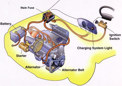
Components of the starting system

1. Battery

Image may contain: text

The automotive battery, also known as a lead-acid storage battery, is an electrochemical device that produces voltage and delivers current. In an automotive battery, we can reverse the electrochemical action, thereby recharging the battery, which will then give us many years of service. The purpose of the battery is to supply current to the starter motor, provide current to the ignition system while cranking, to supply additional current when the demand is higher than the alternator can supply and act as an electrical reservoir.

2. Ignition Switch

The ignition switch allows the driver to distribute electrical current to where it is needed. There are generally 5 key switch positions that are used:

1. Lock- All circuits are open ( no current supplied) and the steering wheel is in the lock position. In some cars, the transmission lever cannot be moved in this position. If the steering wheel is applying pressure to the locking mechanism, the key might be hard to turn. If you do experience this type of condition, try moving the steering wheel to remove the pressure as you turn the key.
2. Off- All circuits are open, but the steering wheel can be turned and the key cannot be extracted.
3. Run- All circuits, except the starter circuit, are closed (current is allowed to pass through). Current is supplied to all but the starter circuit.
4. Start- Power is supplied to the ignition circuit and the starter motor only. That is why the radio stops playing in the start position. This position of the ignition switch is spring loaded so that the starter is not engaged while the engine is running. This position is used momentarily, just to activate the starter.
5. Accessory- Power is supplied to all but the ignition and starter circuit. This allows you to play the radio, work the power windows, etc. while the engine is not running.

Most ignition switches are mounted on the steering column. Some switches are actually two separate parts;

* The lock into which you insert the key. This component also contains the mechanism to lock the steering wheel and shifter.
* The switch which contains the actual electrical circuits. It is usually mounted on top of the steering column just behind the dash and is connected to the lock by a linkage or rod.

3. Neutral Safety Switch

This switch opens (denies current to) the starter circuit when the transmission is in any gear but Neutral or Park on automatic transmissions. This switch is normally connected to the transmission linkage or directly on the transmission. Most cars utilize this same switch to apply current to the backup lights when the transmission is put in reverse. Standard transmission cars will connect this switch to the clutch pedal so that the starter will not engage unless the clutch pedal is depressed. If you find that you have to move the shifter away from park or neutral to get the car to start, it usually means that this switch needs adjustment. If your car has an automatic parking brake release, the neutral safety switch will control that function also.

4. Starter Relay

No photo description available.

A relay is a device that allows a small amount of electrical current to control a large amount of current. An automobile starter uses a large amount of current (250+ amps) to start an engine. If we were to allow that much current to go through the ignition switch, we would not only need a very large switch, but all the wires would have to be the size of battery cables (not very practical). A starter relay is installed in series between the battery and the starter. Some cars use a starter solenoid to accomplish the same purpose of allowing a small amount of current from the ignition switch to control a high current flow from the battery to the starter. The starter solenoid in some cases also mechanically engages the starter gear with the engine.

5. Battery Cables

Battery cables are large diameter, the multistranded wire which carries the high current (250+ amps) necessary to operate the starter motor. Some have a smaller wire soldered to the terminal which is used to either operate a smaller device or to provide an additional ground. When the smaller cable burns, this indicates a high resistance in the heavy cable. Care must be taken to keep the battery cable ends (terminals) clean and tight. Battery cables can be replaced with ones that are slightly larger but never smaller.
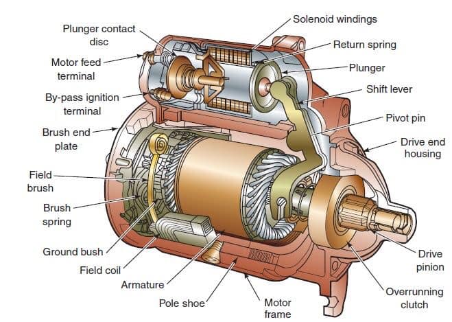
6. Starter Motor

Image may contain: text

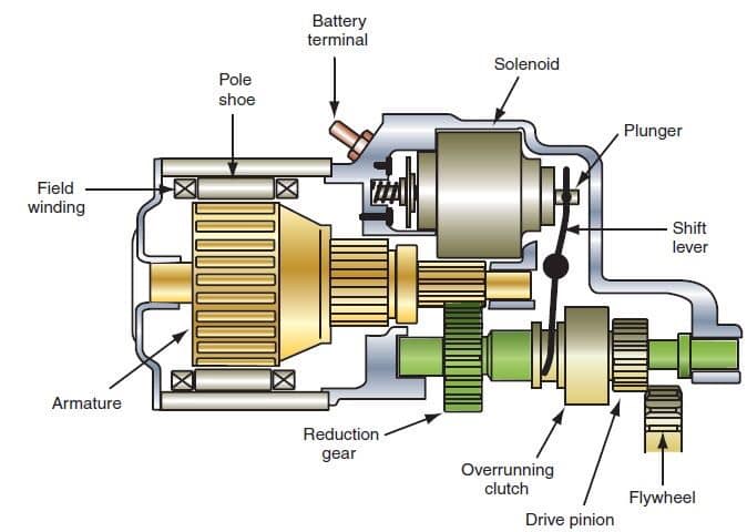
The starter motor is a powerful electric motor, with a small gear (pinion) attached to the end. When activated, the gear has meshed with a larger gear (ring), which is attached to the engine. The starter motor then spins the engine over so that the piston can draw in a fuel/ air mixture, which is then ignited to start the engine. When the engine starts to spin faster than the starter, a device called an overrunning clutch (Bendix drive) automatically disengages the starter gear from the engine gear.

Working principles.

No photo description available.

To make an engine start it must be turned at some speed, so that it sucks fuel and air into the cylinders, and compresses it.

The powerful electric starter motor does the turning. Its shaft carries a small pinion (gear wheel) which engages with a large gear ring around the rim of the engine flywheel.

In a front-engine layout, the starter is mounted low down near the back of the engine.

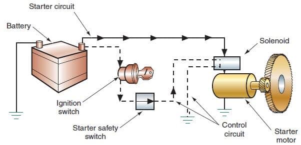
The starter needs a heavy electric current, which it draws through thick wires from the battery. No ordinary hand-operated switch could switch it on: it needs a large switch to handle the high current.

The switch has to be turned on and off very quickly to avoid dangerous, damaging sparking. So a solenoid is used – an arrangement where a small switch turns on an electromagnet to complete the circuit.

The starter switch is usually worked by the ignition key. Turn the key beyond the ‘ignition on’ position to feed current to the solenoid.

The ignition switch has a return spring so that as soon as you release the key it springs back and turns the starter switch off.

When the switch feeds current to the solenoid, the electromagnet attracts an iron rod.

The movement of the rod closes two heavy contacts, completing the circuit from the battery to the starter.

The rod also has a return spring -when the ignition switch stops feeding current to the solenoid, the contacts open and the starter motor stops.

The return springs are needed because the starter motor must not turn more than it has to in order to start the engine. The reason is partly that the starter uses a lot of electricity, which quickly runs down the battery.

Also, if the engine starts and the starter motor stays engaged, the engine will spin the starter so fast that it may be badly damaged.

The starter motor itself has a device, called a Bendix gear, which engages its pinion gear with the gear ring on the flywheel only while the starter is turning the engine. It disengages as soon as the engine picks up speed, and there are two ways by which it does so – the inertia system and the pre-engaged system.

The inertia starter relies on the inertia of the pinion gear – that is, its reluctance to begin to turn.

The pinion gear is not fixed rigidly to the motor shaft – it is threaded on to it, like a freely turning nut on a very coarse-thread bolt.

Imagine that you suddenly spin the bolt: the inertia of the nut keeps it from turning at once, so it shifts along the thread of the bolt.

When an inertia starter spins, the pinion moves along the thread of the motor shaft and engages with the flywheel gear ring.

It then reaches a stop at the end of the thread, begins to turn with the shaft and so turns the engine.

Once the engine starts, it spins the pinion faster than its own starter-motor shaft. The spinning action screws the pinion back down its thread and out of engagement.

The pinion returns so violently that there has to be a strong spring on the shaft to cushion its impact.

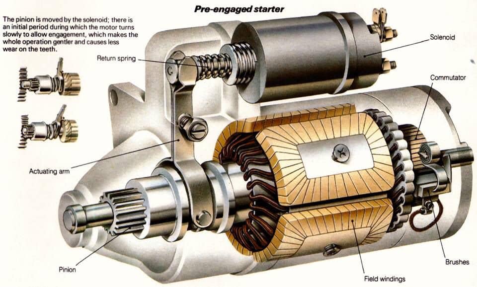
The violent engagement and disengagement of an inertia starter can cause heavy wear on the gear teeth. To overcome that problem the pre-engaged starter was introduced, which has a solenoid mounted on the motor.

There’s more to a car starter system: As well as switching on the motor, the solenoid also slides the pinion along the shaft to engage it.

The shaft has straight splines rather than a Bendix thread so that the pinion always turns with it.

The pinion gear is brought into contact with the toothed ring on the flywheel by a sliding fork. The fork is moved by a solenoid, which has two sets of contacts that close one after the other.

The first contact supplies a low current to the motor so that it turns slowly – just far enough to let the pinion teeth engage. Then the second contacts close, feeding the motor a high current to turn the engine.

The starter motor is saved from over-speeding when the engine starts by means of a freewheel clutch, like the freewheel of a bicycle. The return spring of the solenoid withdraws the pinion gear from engagement.

Sistema de dirección de 4 ruedas, funcionamiento, requerimientos, modos de operación y aplicaciones

FOUR WHEEL STEERING SYSTEM: FUNCTIONS, REQUIREMENTS, MODES OF OPERATION AND APPLICATION

Four-wheel steering, 4WS, also called rear-wheel steering or all-wheel steering, provides a means to actively steer the rear wheels during turning maneuvers. A system that uses all four wheels to steer the car. The steering angle is usually limited to 2° or 3°. Turning the rear wheels in the opposite direction to the front at slow speeds can allow faster maneuvering and a much tighter turning radius. Turning the rear wheels in the same direction as those at the front at high speed allows sudden lane changes with much greater stability. Turning the rear wheels in the same direction as the front when parking makes parallel parking much easier. Four-wheel steering is a relatively new technology that improves maneuverability in cars, trucks and trailers.

FUNCTIONS

• To provide directional stability of vehicle
• To facilitate straight ahead recovery
• To minimize tire wear
• To absorb major parts of the road shocks
• To provide perfect rolling motions of the road wheels

REQUIREMENTS

No photo description available.

The steering system has the following requirements:

• The steering system must be able to turn the front wheels sharply yet easily and smoothly.
• The steering should be made lighter at low speeds and heavier at high speeds.
• Smooth recovery while the vehicle is turning.
• Minimum transmission of shock from road surface.

MODES OF 4WS

1. Two Wheel Steer: 
A 4-Wheel Steering System is flexible enough to work as a 2-wheel steer by restricting the rear wheel movement.

2. Four Wheel Steer/ Slow Speeds: 
Front wheel directions are opposite to rear wheel directions. This helps to take sharp turn with least turning radius.
At slow speeds, the rear wheels turn in the direction opposite to the front wheels. It can reduce the turning circle radius by 25%, and can be equally effective in congested city conditions, where U-turns and tight streets are made easier to navigate.

3. Crab Steer Mode/ High Speeds: 
At high speed lane change, both the front and rear wheels face in same direction.
In high speeds, turning the rear wheels through an angle opposite to front wheels might lead to vehicle instability and is thus unsuitable. Hence, at speeds above 80 kmph, the rear wheels are turned in the same direction of front wheels in four-wheel steering systems.

4. Zero turn: 
Front and Rear wheels are so aligned that the vehicle moves in a circle of ‘’zero radius’’.

APPLICATIONS

• Parking: 
During a parking a vehicles driver typically turns the steering wheels through a large angle to achieve a small tuning radius. By counter phase steering of the rear wheels, 4ws system realizes a smaller turning radius then is possible with 2ws system. As a result, vehicle is turned in small radius at parking.

• Junctions:
On a cross roads or other junction where roads intersect at 900 degrees or tighter angles, counter phase steering of the rear wheels causes the front and rear wheels to follow more or-less path. As a result, the vehicle can be turned easily at a junction.

• Slippery road surfaces: 
During steering operation on low friction surfaces, steering of the rear wheels suppress sideways drift of the vehicle’s rear end. As a result, the vehicles direction is easier to control.

• High-speed straight-line operation: 
When traveling in a straight line at high speed, a vehicle’s driver frequently needs to make small steering correction to maintain the desired direction, in phase steering of the rear wheels minimizes these corrective steering inputs.

• Narrow roads: 
On narrow roads with tight bends, counter-phase steering of the rear wheels minimizes the vehicle’s turning radius, thereby reducing side-to –side rotation of the steering wheels and making the vehicle easier to turn.

ADVANTAGES

• Car more efficient and stable on cornering.
• Improved steering responsiveness and precision.
• High-speed straight-line stability.
• Notable improvement in rapid, easier, safer lane changing maneuvers.
• Smaller turning radius and tight space maneuverability at low speed.
• Relative Wheel Angles and their Control.
• Risk of hitting an obstacle is greatly reduced

¿Qué es un diferencial? Conoce su funcionamiento, componentes y tipos de diferenciales

Image may contain: text

DIFFERENTIAL: FUNCTIONS, WORKING PRINCIPLES AND CLASSIFICATION

Differential is a very important part in a vehicle, as a component transfer the engine power is transmitted to the wheels. Engine power is transferred by a rear propeller shaft to wheel first changed direction by differential rotation are then referred to rear axle shafts after that to the rear wheels.

Differential functions to reduce the speed received by the propeller shaft to produce a great moment and to change the direction of rotation of the propeller shaft 900 is transmitted to wheel next round through the rear axle shaft rear separately. However, if the differential is not working then it will result in the vehicle which cannot be run A.

HOW IT WORKS?

At the time of straight road.

During the vehicle runs straight, the wheels of the rear axle will be screened by the drive pinion through the ring gear differential case, wheel-wheel differential gear pinion shaft, wheel-pinion differential gears, side gear teeth is not spinning, remain to be drawn into the ring gear rotation. Thus the spin on the wheel left and right alike.

At the time of turning.

At the time of vehicle turning left prisoners left wheel is bigger than the right wheel. If the differential case with the ring gear rotates the pinion will rotate on its axis and also the movement around the left side gear, so round the right hand side gear increases, the side where the number of revolutions of the gear which is 2 times round the ring gear. It can be said that the average second round gear is comparable with the rotary ring gear. as it should.

WORKING PRINCIPLE OF DIFFERENTIAL

The basic principle of the differential gear unit can be understood by using equipment that consists of two gears pinion and rack. Both rack can be moved in the vertical direction as far as the weight rack and slip resistance will be lifted simultaneously. Placed between the tooth pinion rack and pinion gear connected to the braces and can be moved by these braces. When the same load “W” placed on each rack then braces (Shackle) is pulled up the second rack would be lifted at the same distance, this will prevent the pinion gear does not rotate. But if a greater burden placed on the left rack and pinion buffer will then be drawn up along the gear rack rotates the load gets heavier, which is attributed to differences in prisoners who are given the pinion gear, so the smaller the burden will be lifted. The raised rack spacing is proportional to the number of turns pinion gear. In other words that rack gets custody larger still and while prisoners who received a smaller load will move. This principle is used in the planning of differential gears.

FUNCTIONS OF DIFFERENTIAL

1. Further reduces the rotations coming from the gear box before the same are passed on to the rear axles.
2. Changes the direction of axis of rotation of the power by 90o i.e. from being longitudinal to transverse direction.
3. To distribute power equally to both the rear driving axles when the tractor is moving in straight ahead direction.
4. To distribute the power as per requirement to the driving axles during turning i.e. more rotations are required by the outer wheel as compared to the inner wheel – during turns.

THE MAIN COMPONENTS OF THE DIFFERENTIAL

1. Input pinion gear
2. Crown wheel gear
3. Differential cage
4. Differential star
5. Differential axle (sun) gear

TYPES OF DIFFERENTIALS

1. Open Differential
2. Locked Differential
3. Viscous Limited Slip Differential
4. Mechanical Clutch-Type LSD (Including eLSD)
5. Torsen & Helical Differential
6. Torque Vectoring Differential

1. Open Differential

Image may contain: text

Open differentials are the most basic form of a differential. The purpose is to allow for different speeds between the two wheels, while torque split is held constant at 50/50. A common misconception with open differentials is that when one wheel is lifted, 100 per cent of the torque is sent to it. This is not true, however the amount of torque sent to the wheel with traction is very low because the amount of torque required to spin a wheel is also low. Remember, both wheels always receive equal torque, but if one has no resistance (eg. if it’s in the air), the amount of torque sent to the drive axle as a result is very low.
• Splits the engine torque into two outputs
• Allows the wheels to rotate at different speeds
• When one tire loses traction, the opposing tire will also lose power
• Found in family sedans and economy cars

Advantages:
• Allows for completely different wheel speeds on the same axle, meaning no wheel slip will occur while going around a corner, as the outside tyre will travel further.
• From an efficiency standpoint, less energy will be lost through the differential versus alternative options.
• Cost.

Disadvantages:
• When one wheel has poor traction, this drastically limits the amount of power the vehicle can put down. Because the torque distribution is always 50/50, if one wheel cannot put down much power, the other will receive an equally low amount of torque.

2. Locked Differential (Including Locking And Welded Diffs)

Locked differentials are on the opposite side of the spectrum versus open diffs. The purpose is for wheel speed to remain constant between the two wheels, and the major benefit here is that torque will go to the wheel with traction, up to 100 per cent at a single wheel. For off-road use, it is common for the differential to have a locking feature, so that it is open when driving on pavement.
• Connected wheels always spin at the same speed
• Turning the vehicle can be very difficult
• Found in Jeep Wranglers and most full-size trucks

Advantages:
• Allows for torque to go to the wheel with the most traction. For all differential styles, this will allow for the most torque to reach the ground on any surface condition.
• For off-road use where tyre wear is not an issue, this is about as good as it gets. Robust, simple, and very effective.
• In situations where it’s desirable to keep wheel speed constant on an axle (ex: drifting), this is an easy solution (a welded differential works exactly the same).

Disadvantages:
• A locked differential will not allow for wheel speed differences between the right and left wheels. This means additional tyre wear, as well as binding within the drivetrain as a result.

3. Viscous Limited-Slip Differential (VLSD)

VLSD are fairly simple as far as operation, however they have some drawbacks in comparison to other forms of LSDs.
• Combination of open and locking differentials
• Usually acts as an open differential
• Automatically locks when slipping occurs
• Found in sports vehicles like Nissan 370Z and the Mazda MX-5 Miata

Advantages:
• Allows for different wheel speeds on an axle, thus reducing tyre wear versus a locked differential (the same applies for all forms of LSD, but this style is particularly good for it).
• Allows for torque to be sent to the wheel which has more traction.
• Very smooth operating, typically won’t have the low speed clunkiness associated with other LSD types navigating in a tight radius (eg. parking lots).

Disadvantages:
• Cannot fully lock up, the system requires a speed differential between the two sides in order to transfer torque.
• As the internal gear fluid heats up (in cases where it’s being used too frequently), the effect of the LSD will be reduced.

4. Mechanical Clutch-Type LSD (Including eLSD)

Clutch type LSDs come in a wide variety. one-way, 1.5-way, two-way, and even electronic. In principle, they all operate very similarly, with a clutch pack that attempts to lock up the differential, allowing for torque to be sent to the wheel with the most grip.

Advantages:
• Applies lock when throttle is applied. Unlike a VSLD, this means that torque split can occur before one wheel reaches a different speed (similar to a locked differential).
• For one-way LSDs, the differential acts like an open diff when not on the gas, thus easily allowing for different wheel speeds while cornering.
• For two-way LSDs, the differential applies locking force while decelerating, which in some cases can help with braking stability.
• Works well even if one wheel is off the ground or has limited traction.
• Electronic LSDs allow for the clutch engagement to be controlled by the onboard computers, optimising lock based on the driving conditions.

Disadvantages:
• Often requires regular oil changes, and the clutches may wear out eventually requiring replacement.
• Electronic LSDs will add cost and complexity.

5. Torsen & Helical Differentials

Torsen and helical differentials work in a fairly similar fashion, using clever gearing to apply locking force to transfer torque to the wheel with more grip. They’re great for street use and even light track use, though they do have a disadvantage.

Advantages:
• These differentials begin to send more torque to the slower-rotating wheel the instant there is a speed differential between them. Essentially, it reacts far quicker than a VLSD.
• These are purely mechanical systems, with no routine maintenance required as the differential action is dependent upon friction throughout the gears.

Disadvantages:
• When one wheel is in the air, a Torsen diff acts very similarly to an open differential, and very little torque is sent to the drive axle. For street use this is completely acceptable, but it may be an issue for more purpose built vehicles on the track.

6. Torque Vectoring Differential (TVD)

Without a doubt the most complex of the differentials, this option allows for the greatest amount of control by the developers, meaning unique programming to react to any situation, as well as the ability to help induce yaw.
• Uses additional gear trains
• Fine tunes the torque delivered to each drive wheel
• Can slow down or quicken the car’s rotation around a corner
• Heavy, complex and low-performing for fuel economy
• Found in the BMW X5 M or the Lexus RC F

Advantages:
• Allows for more torque to be sent to the outside wheel while cornering. In general, LSDs will send torque to the wheel which is rotating at a slower speed. This is because a greater wheel speed is perceived as slip, so the LSD locks up to send more torque to the slower wheel and prevent wheel slip. When accelerating out of a corner, a TVD sends more torque to the outside wheel, helping to induce yaw and rotate the vehicle.
• Allows for complete control by the designer, the system can choose in what situations the vehicle will send more torque to either wheel, rather than being reactive.
• Can send up to 100 per cent of available torque to a single wheel

Automotive World

¿Qué son las «BUJÍAS» y que partes las componen?

SPARK PLUG: FUNCTIONS, CONSTRUCTION, WORKING PRINCIPLE AND TYPES

Image may contain: text

A spark plug is an electrical device that fits into the cylinder head of some internal combustion engines and ignites compressed aerosol gasoline by means of an electric spark. Spark plugs have an insulated center electrode which is connected by a heavily insulated wire to an ignition coil or magneto circuit on the outside, forming, with a grounded terminal on the base of the plug, a spark gap inside the cylinder.

The spark plug has two primary functions:

1. To ignite the air/fuel mixture. 
Electrical energy is transmitted through the spark plug, jumping the gap in the plugs firing end if the voltage supplied to the plug is high enough. This electrical spark ignites the gasoline/air mixture in the combustion chamber.

2. To remove heat from the combustion chamber. 
Spark plugs cannot create heat, they can only remove heat. The temperature of the end of the plug\’s firing end must be kept low enough to prevent pre-ignition, but high enough to prevent fouling. The spark plug works as a heat exchanger by pulling unwanted thermal energy from the combustion chamber and transferring heat to the engines cooling system. The heat range of a spark plug is defined as its ability dissipate heat from the tip.

CONSTRUCTION

No photo description available.

1. Ribs-
Insulator ribs provide added protection against secondary voltage or spark flashover and also help to improve the grip of the rubber spark plug boot against the plug body.
The insulator body is molded from aluminum oxide ceramic. In order to manufacture this part of the spark plug, a high-pressure, dry molding system is utilized. After the insulator is molded, it is kiln-fired to a temperature that exceeds the melting point of steel. This process results in a component that features exceptional dielectric strength, high thermal conductivity and excellent resistance to shock.

2. Insulator:
The insulator body is molded from aluminum oxide ceramic. In order to manufacture this part of the spark plug, a high-pressure, dry molding system is utilized. After the insulator is molded, it is kiln-fired to a temperature that exceeds the melting point of steel. This process results in a component that features exceptional dielectric strength, high thermal conductivity and excellent resistance to shock.
The pointer shows the spark plug insulator. As mentioned above, it is formed from aluminum oxide ceramic. The outer surface is ribbed to provide grip for the spark plug boot and to simultaneously add protection from spark flashover (crossfire).

3. Hex:
The hexagon provides the contact point for a socket wrench. The hex size is basically uniform in the industry and is generally related to the spark plug thread size.

4. Shell: 
The steel shell is fabricated to exact tolerances using a special cold extrusion process. Certain types of spark plugs make use of a steel billet (bar stock) for shell construction.

5. Plating:
The shell is almost always plated. This enhances durability and provides for rust and corrosion resistance. The steel shell is fabricated to exact tolerances using a special cold extrusion process or in other specialized cases, machined from steel billet. The hexagon machined onto the shell allows you to use a socket wrench to install or remove the plug.

6. Gasket:
Certain spark plugs use gaskets while other examples are “gasketless.” The gasket used on spark plugs is a folded steel design that provides a smooth surface for sealing purposes. Gasketless spark plugs use a tapered seat shell that seals via a close tolerance incorporated into the spark plug.

7. Threads: 
Spark plug threads are normally rolled, not cut. This meets the specifications set forward by the SAE along with the International Standards Association.

8. Ground electrode:
There are a number of different ground electrode shapes and configurations, but for the most part, they are manufactured from nickel alloy steel. The ground electrode must be resistant to both spark erosion and chemical erosion, both under massive temperature extremes.

9. Center electrode:
Center electrodes must be manufactured from a special alloy that is resistant to both spark erosion and chemical corrosion. Keep in mind that combustion chamber temperatures vary (and sometimes radically). The center electrode must live under these parameters.

10. Spark park electrode gap: 
The area between the ground electrode and the center electrode is called the gap. Center electrodes must be manufactured from a special alloy that is resistant to both spark erosion and chemical corrosion.

11. Insulator nose:
There are a large number of insulator nose shapes and sizes available, but in essence, the insulator nose must be capable of shedding carbon, oil and fuel deposits at low speeds. At higher engine speeds, the insulator nose is generally cooled so that temperatures and electrode corrosion are reduced.

No photo description available.

WORKING PRINCIPLE

No photo description available.

The spark plug is connected to a high voltage source like the magneto or the ignition coil at one end. The other end with the two electrodes is immersed into the combustion chamber. When current passes through the terminal and into the main center electrode, a potential difference (voltage drop) is created between two electrodes. The gas mixture that occupies the gap between them acts as an insulator and thus the electricity doesn’t flow beyond the tip of the center electrode.

But as the voltage increases, the gases in the gap begin to get energized. Once the voltage increases to the point that crosses the dielectric strength (resistance to conduct electricity) of the gases, they become ionized. Once the gases get ionized, they begin to act as conductors and permit the current to travel through the insulating gap. When the dielectric strength is crossed, the electrons begin to surge through that gap. This sudden movement of electrons rapidly increases the heat in that region due to which they begin to expand rapidly causing a mini explosion which results in the formation of a spark.

No photo description available.

TYPES

No photo description available.

Spark Plugs can be put into two different primary classifications, based on their operating temperatures and based on their construction.

Based on Operating Temperatures

Once the combustion process is completed in the combustion cycle, the heat generated needs to dissipate. The heat escapes through the exhaust gases, the cylinder wall of the engine and the spark plug surface. Based on the operating temperature and level of heat dissipation, spark plugs can be classified into two types:

1. Hot Spark Plug: 
A hot spark plug operates in a higher temperature range. It has a lesser ceramic area which is used to insulate the heat. A hot spark plug dissipates lesser combustion heat and allows the tip and electrode to stay hotter. This ensures that any deposit accumulation is burned off and isn’t allowed to stay for long.

2. Cold Spark Plug: 
For high-performance engines that run hot by default, using a hot spark plug will cause pre-ignition. In extreme cases, it can also lead to the tip melting off. In such cases, a cold spark plug is used. Here the ceramic insulation area is higher and this it will dissipate more heat. But on the flipside, it is prone to greater deposit accumulation. Be sure to follow your instruction manual and use the correct type of plug recommended for your engine for optimum performance.

Based on Material Used

Spark Plugs are further classified based on the material used on the ends of the electrodes. 
They are of 4 types:

1. Copper- Nickel Type: 
These are the most basic types of spark plugs. Here the center electrode is made of a copper-nickel alloy as copper on its own is very weak and will melt off due to engine heat. Nickel is added to strengthen the plug but even then these are the weakest types available in the market. They are also required to be made with a larger diameter and hence require more voltage for operation.

2. Single Platinum Type: 
These plugs have a small platinum disc on the tip of the center electrode. This platinum tip is exponentially stronger than a copper-nickel coating making this type of plug last long as well. They are also less prone to debris build up.

3. Double Platinum Type: 
These plugs have platinum tips on both the center electrode and the side electrode. They spark up twice in the combustion cycle, once before the combustion and once during the exhaust stroke. The second spark is wasted and so this spark plug can only be used if your vehicle is equipped with a waste spark ignition type distributor.

4. Iridium Type: 
These are the best spark plugs available in the market. Here the tip of the center electrode is made of Iridium which is the strongest out of nickel, copper, and platinum. Hence, they are the least prone to deposits and damage. They also have a small sized electrode which requires less voltage for operation as well. Iridium plugs are much more expensive than the other types but then again you pay for what you get.

¿Cómo funciona el sistema de escape en nuestro motor, y cuáles son los componentes que lo integran?

EXHAUST SYSTEM: COMPONENTS AND THEIR FUNCTION

The exhaust system collects the exhaust gases from the cylinders, removes harmful substances, reduces the level of noise and discharges the purified exhaust gases at a suitable point of the vehicle away from its occupants…

FUNCTION

The exhaust system collects the exhaust gases from the cylinders, removes harmful substances, reduces the level of noise and discharges the purified exhaust gases at a suitable point of the vehicle away from its occupants. The exhaust system can consist of one or two channels depending on the engine. The flow resistance must be selected so that the exhaust back pressure affects engine performance as little as possible. To ensure that the exhaust system functions perfectly, it must be viewed as a whole and developed accordingly. This means that its components must be coordinated by the design engineers in line with the specific vehicle and engine.

No photo description available.

In addition to all the complex functions which the exhaust system has to perform, it is also subject to extreme stresses. The fuel-air mixture in the cylinders is abruptly heated to temperatures up to 2,400 °C. This causes it to expand greatly before escaping into the exhaust system at supersonic speed. This noise level resembles the crack of an explosion and must be reduced by approx. 50 dB(A) as it travels from the engine exhaust valve to the end of the exhaust system.

Apart from temperature and pressure stresses, the exhaust system must also cope with vibrations from the engine and bodywork as well as vibrations and jolting from the carriageway. The exhaust system additionally has to resist corrosion attacking from the inside caused by hot gases and acid, and from the outside in the form of moisture, splashed water and salt water. There is also the risk that the catalyst may be poisoned through sulfur or lead present in the fuel.

COMPONENTS OF EXHAUST SYSTEM

No photo description available.

1. Exhaust manifold:

The exhaust manifold attaches to the cylinder head and takes each cylinder’s exhaust and combines it into one pipe. The manifold can be made of steel, aluminum, stainless steel, or more commonly cast iron.

2. Oxygen sensor:

All modern fuel injected cars utilize an oxygen sensor to measure how much oxygen is present in the exhaust. From this, the computer can add or subtract fuel to obtain the correct mixture for maximum fuel economy. The oxygen sensor is mounted in the exhaust manifold or close to it in the exhaust pipe.

3. Catalytic converter:

This muffler like part converts harmful carbon monoxide and hydrocarbons to water vapor and carbon dioxide. Some converters also reduce harmful nitrogen oxides. The converter is mounted between the exhaust manifold and the muffler.

Selective Catalytic Reduction (SCR)

No photo description available.

This technology uses ammonia to break down dangerous NOx emissions produced by diesel engines into nitrogen and water. In automotive applications, SCR delivers ammonia through a urea solution – Diesel Exhaust Fluid (DEF) – which is sprayed into the exhaust stream by an advanced injection system and then converted into ammonia on a special catalyst.

No photo description available.

SCR is the technology of choice for the majority of truck and engine manufacturers to meet 2010 emissions standards for heavy-duty trucks.

Aside from helping the environment, the biggest benefit of SCR for vehicle owners is the fuel efficiency the technology provides. Because SCR deals with emissions in the exhaust pipe, engineers are able to tune the engine to provide more torque and reduce fuel consumption.

4. Muffler/Silencer:

Every internal combustion engine produces «exhaust noise» due to the pulsating emission of gases from the cylinders. This noise has to be silenced by reducing the sound energy of the exhaust gas flow. There are two basic options here: Absorption and reflection of the sound in the silencer. These two principles are generally combined in a single silencer. Exhaust chambers and exhaust flaps are other sound-absorbing and sound-modifying elements that can be used to eliminate especially undesirable frequencies from the outlet noise. Catalytic converters also have a sound-absorbing effect.

The exhaust system is itself a system subject to vibration, it produces noise itself through natural frequencies and vibration which are transmitted to the car body. Careful coordination of the entire system is, therefore, necessary here. This includes the design and positioning of the individual elements of the exhaust system and their flexible mountings.

The muffler serves to quiet the exhaust down to acceptable levels. Remember that the combustion process is a series of explosions that create a lot of noise. Most mufflers use baffles to bounce the exhaust around dissipating the energy and quieting the noise. Some mufflers also use fiberglass packing which absorbs the sound energy as the gases flow through.

5. Resonator

The muffler alone cannot always quiet all the engine noise. Many exhaust systems also include a resonator which is like a mini-muffler. They are usually straight pipes filled with sound muffling materials. The resonator can be either before or after the muffler in the exhaust system.

6. Exhaust pipe:

Between all of the above mention parts is the exhaust pipe which carries the gas through it’s journeys out your tailpipe. Exhaust tubing is usually made of steel but can be stainless steel (which lasts longer due to its corrosion resistance) or aluminized steel tubing. Aluminized steel has better corrosion resistance than plain steel but not better than stainless steel. It is, however, cheaper than stainless steel.

HOW TO IDENTIFY PROBLEMS

Although the exhaust system is located underneath the vehicle, there are some symptoms you can look out for which may indicate that there is a problem with your exhaust.

1.Noises

A loud roaring noise could indicate corrosion to the exhaust system
A hissing sound could mean that gas is escaping through a crack or hole in one of the exhaust components
Chugging noises mean that there may be a blockage in one of the pipes
A persistent and rapid succession of knocking sounds indicate that a part of the exhaust may have come loose

2. Emissions

White smoke – this is not smoke but in fact, vapor and you should see this when you first start your car as it indicates that the engine is warming up. If white smoke is visible after the engine is warm it may indicate internal leaks or cracks.

Blue smoke – A bluish-grey smoke means that oil may be burning in the combustion chamber. This could mean that the cylinder is worn or there are leaks in the valve seals.

Black smoke – very black smoke is often accompanied by increased fuel consumption and may signify leaks in the exhaust system or a problem with the engine.

3. Visual

Inspect the components of your exhaust that you can see for any signs of rust or corrosion. Make sure you keep an eye out for any cracks and holes and contact a specialist if you do find any signs of damage.

VALVE TIMING DIAGRAM OF TWO STROKE AND FOUR STROKE ENGINES: THEORETICAL AND ACTUAL

A valve timing diagram is a graphical representation of the opening and closing of the intake and exhaust valve of the engine, The opening and closing of the valves of the engine depend upon the movement of piston from TDC to BDC, This relation between piston and valves is controlled by setting a graphical representation between these two, which is known as valve timing diagram.

The valve timing diagram comprises of a 360 degree figure which represents the movement of the piston from TDC to BDC in all the strokes of the engine cycle, Which is measured in degrees and the opening and closing of the valves is controlled according to these degrees.

WHY DO WE NEED VALVE TIMING DIAGRAM?

The normal engine completes around 100000 cycles per minute, as we know there are number of processes involve in a single cycle (from the intake of the air-fuel mixture to the exhaust of the combustion residual) of a internal which makes it necessary to be equipped with an effective system that can enable

 Synchronisation between the steps of a cycle of the engine from intake of air-fuel ratio to the exhaust of combustion residual.
 Complete seizure of the combustion chamber at the instant at which the combustion of air-fuel mixture takes place as the leakage can cause damage to the engine and can be hazardous.
 Provide engine with a mixed air and fuel or air in case of diesel engine when required ( at the time of suction) which is the necessity of the engine.
 Provide the exit for the combustion residual so that the next cycle of the engine can take place.
 Ideal timing for the opening and closing of the inlet and outlet valve which in turn protect the engine from defects like knocking or detonation.
 A high compression ratio required to combust the fuel especially in case of diesel engine by overlapping the closing of the valve.
 The cleaning of engine cylinder which in turn maintain the quality of combustion and decreases wear and tear inside the cylinder.
 The study of the details of the combustion that is required for the modification of the power of the engine.
So due to these reasons a engine weather it is 2-stroke or 4-stroke is designed according to the valve timing diagram, so that the movement of piston from TDC to BDC is provided with the ideal timing of opening and closing of the intake and exhaust valves respectively.

VALVE TIMING DIAGRAM FOR 4-STROKE ENGINE (PETROL AND DIESEL)

As we all know in 4-stroke engine the cycle completes in 4-strokes that are suction, compression, expansion and exhaust , The relation between the valves (inlet and outlet) and piston movement from TDC to BDC is represented by the graph known as valve timing diagram.

THEORETICAL

Suction Stroke-

The engine cycle starts with this stroke, Inlet valve opens as the piston which is at TDC starts moving towards BDC and the air-fuel mixture in case of petrol and fresh air in case of diesel engine starts entering the cylinder,till the piston moves to BDC.

Compression Stroke-

After the suction stroke the piston again starts moving from BDC to TDC in order to compress the air-fuel (petrol engine) and fresh air (diesel engine) which in turn raises the pressure inside the cylinder which is essential for the combustion of the fuel.
 The inlet valve closes during this operation to provide seizure of the chamber for the compression of the fuel.

Expansion Stroke-

After compressing the fuel, The combustion of the fuel takes place which in turn pushes the piston which is at TDC towards BDC in order to release the pressure developed by the combustion and output is obtained .
Note – In petrol engine combustion takes place due to the spark produced by the spark plug.
 In petrol engine the air and fuel charge enters the cylinder during suction stroke.
 In diesel engine combustion occurs due to the high compression provided by the compression stroke which is responsible for raising the temperature inside cylinder upto auto-ignition temperature of the diesel and air charge.
 In diesel engine the fresh air enters inside the cylinder during suction stroke and the fuel is sprayed by the fuel injectors over the air.

Exhaust Stroke-

After expansion stroke the piston which is at BDC starts moving towards TDC followed by the opening of exhaust valve for the removal of the combustion residual
 Exhaust valve closes after the piston reaches TDC.

ACTUAL OR PRACTICAL PROCESS

In suction stroke of 4-stroke engine the inlet valve opens 10-20 degree advance to TDC for the proper intake of air-fuel(petrol) or air (diesel) ,which also provides cleaning of remaining combustion residuals in the combustion chamber.
 When the piston reaches BDC the compression stroke starts and again the piston starts moving towards TDC ,The inlet valve closes 25-30 degree past the BDC during the compression stroke,which provide complete seizure of the combustion chamber for the compression of air-fuel(petrol engine)and air(diesel engine).


 During the compression stroke as the piston moves towards TDC ,combustion of fuel takes place 20-35 degree before TDC which provides the proper combustion of fuel and proper propagation of flame.
 The expansion strokes starts due to the combustion of fuel which in turn releases the pressure inside the combustion chamber and provide rotation to the crank shaft,The piston moves from TDC to BDC during expansion stroke which continuous 30-50 degree before BDC.
 The exhaust valve opens 30-50 degree before BDC which in turn starts the exhaust stroke and the exhaust of the combustion residual takes place with movement of the piston from BDC toTDC which continues till the 10-20 degree after the piston reaches TDC.
As we can see in the entire cycle of engine valves overlap 2 times i.e. closing of both valves during compression stroke and opening of both valves during exhaust stroke.

VALVE TIMING DIAGRAM FOR 2-STROKE ENGINE

In 2-stroke petrol engine as we all know the engine cycle completes in 2-strokes i.e expansion stroke and compression stroke, The fuel intake and combustion residual exhaust occurs respectively during these 2 strokes.

THEORETICAL VALVE TIMING

Expansion stroke-

At the beginning of the expansion stroke the piston which is at TDC starts moving towards BDC due to the combustion of compressed air-fuel (petrol engine) and (diesel sprayed charge in diesel engine) during compression stroke and the power output is obtained.
 The air-fuel(petrol engine) and air (diesel diesel) enters through the inlet port during the expansion strokes as the piston moves from TDC to BDC during this stroke.
 The expansion stroke continuous till the piston reaches BDC.

Compression Stroke-

At the end of the expansion stroke the piston which is at BDC starts moving towards TDC and the compression of air-fuel(petrol engine) and diesel sprayed charge(diesel engine) starts along with the exhaust of combustion residual through exhaust port due to the movement of piston from BDC to TDC.
 The piston closes both inlet port and exhaust port due to its movement from BDC to TDC which in turn raises the pressure inside the combustion chamber.
 At the end of the compression stroke i.e. when the piston reaches TDC combustion of the air-fuel (petrol engine) due to spark and diesel sprayed charge (diesel engine) due to the high pressure takes place, And the cycle repeats again.

ACTUAL OR PRACTICAL PROCESS


 Before the expansion stroke i.e. completion of the compression stroke, the inlet port open 10-20 degree before the piston reaches the TDC which in turn starts the expansion stroke due to the combustion of air-fuel (petrol engine) from the crankcase and air (diesel engine) entered from the inlet port which in turn pushes the piston towards BDC.
 The inlet port closes 15-20 degree after TDC during the expansion stroke of the 2-stroke engine.
 Due to the movement of piston from TDC to BDC during expansion stroke exhaust port opens 35-60 degree before the piston reaches BDC which in turn starts the exhaust of the combustion residual..
 Transfer port open 30-45 degree before BDC for scavenging process.
 When the piston moves towards TDC from BDC the transfer port closes 30-45 degree after BDC which in turn stops the scavenging process.
 During the movement of piston from BDC to TDC exhaust valve closes 35-60 degree after BDC which seizes the combustion chamber and pressure inside the combustion chamber increases due to the start of compression stroke.and the cycle starts again.
 The air fuel mixture (petrol engine) and air ( diesel engine) is transported to the cylinder during the opening of the transfer port.
Note – The opening and closing of valves few degrees before TDC and BDC is required for normal working of the engine as this degree gaps provides proper completion of the operation of strokes and prevents the engine from defects like knocking, and also causes less emission.
 For power modification this valve timing is adjusted which in turn increases the power and torque of the engine but decreases the economy.
In this article we have learnt about valve timing diag

✅¿Qué es y como funcionan los pistones automotrices? ¿Cuáles son las partes de un pistón automotriz?✅ Explicación detallada y con imágenes

No photo description available.

A piston is a cylindrical engine component that slides back and forth in the cylinder bore by forces produced during the combustion process. The piston acts as a movable end of the combustion chamber. The stationary end of the combustion chamber is the cylinder head. Pistons are commonly made of a cast aluminum alloy for excellent and lightweight thermal conductivity. Thermal conductivity is the ability of a material to conduct and transfer heat.

No photo description available.

Aluminum expands when heated, and proper clearance must be provided to maintain free piston movement in the cylinder bore. Insufficient clearance can cause the piston to seize in the cylinder. Excessive clearance can cause a loss of compression and an increase in piston noise.

There are also secondary functions fulfilled by the piston:

 contributes to heat dissipation generated during combustion
 ensures the sealing of the combustion chamber, preventing gas leakages from it and oil penetration into the combustion chamber
 guides the movement of the connecting rod
 ensures to the continuous change of gases in the combustion chamber
 generates the variable volume in the combustion chamber

The piston is the component of the internal combustion engine (ICE) which has to sustain the most mechanical and thermal stress. Due to the piston, the power of the ICE is limited. In case of very high thermal or mechanical stress, the piston is the first component to fail (compared to engine block, valves, cylinder head). This is because the piston must be a compromise between mass and mechanical and thermal stress resistance.

No photo description available.

The geometry of the piston is constrained due to the cubic capacity of the ICE. Therefore, the main way to increase the mechanical and thermal resistance of the piston is by increasing its mass. This is not recommended because a piston with high mass, has high inertia which translates in high dynamic forces, especially during high engine speed. The resistance of the piston can be improved by geometry optimization but there will be always a compromise between mass and mechanical and thermal resistance.

As you can see there are significant differences between diesel and gasoline pistons. Diesel pistons must withstand higher pressures and temperatures, therefore they are bigger, bulkier and heavier. They can be manufactured from aluminium alloys, steel or a combination of both. Gasoline engine pistons are lighter, designed for higher engine speeds. They are manufactured from aluminium alloys.

The piston crown comes in direct contact with the burning gases, within the combustion chamber, so it’s exposed to high thermal and mechanical stress. Depending on the type of the engine (diesel or gasoline) and the type of fuel injection (direct or indirect injection), the piston crown can be flat or can contain a bowl.

PISTON PARTS

1. piston pin
2. skirt
3. ring grooves
4. ring lands, and 
5. piston rings.

No photo description available.

1. Piston head
It is the top surface (closest to the cylinder head) of the piston which is subjected to tremendous forces and heat during normal engine operation.

2. Piston pin bore
A piston pin bore is a through hole in the side of the piston perpendicular to piston travel that receives the piston pin.

3. Piston pin
A piston pin is a hollow shaft that connects the small end of the connecting rod to the piston.

4. Skirt 
The skirt of a piston is the portion of the piston closest to the crankshaft that helps align the piston as it moves in the cylinder bore. Some skirts have profiles cut into them to reduce piston mass and to provide clearance for the rotating crankshaft counterweights.

5. Ring grooves 
A ring groove is a recessed area located around the perimeter of the piston that is used to retain a piston ring.

6. Ring land
Ring lands are the two parallel surfaces of the ring groove which function as the sealing surface for the piston ring.

7. Poston ring
A piston ring is an expandable split ring used to provide a seal between the piston an the cylinder wall. Piston rings are commonly made from cast iron. Cast iron retains the integrity of its original shape under heat, load, and other dynamic forces. Piston rings seal the combustion chamber, conduct heat from the piston to the cylinder wall, and return oil to the crankcase. Piston ring size and configuration vary depending on engine design and cylinder material.

Piston rings commonly used on small engines include:

1. Compression Ring
2. Wiper Ring 
3. Oil Ring

1. Compression ring, 
A compression ring is the piston ring located in the ring groove closest to the piston head. The compression ring seals the combustion chamber from any leakage during the combustion process. When the air-fuel mixture is ignited, pressure from combustion gases is applied to the piston head, forcing the piston toward the crankshaft. The pressurized gases travel through the gap between the cylinder wall and the piston and into the piston ring groove. Combustion gas pressure forces the piston ring against the cylinder wall to form a seal. Pressure applied to the piston ring is approximately proportional to the combustion gas pressure.

2. Wiper ring
A wiper ring is the piston ring with a tapered face located in the ring groove between the compression ring and the oil ring. The wiper ring is used to further seal the combustion chamber and to wipe the cylinder wall clean of excess oil. Combustion gases that pass by the compression ring are stopped by the wiper ring.

3. Oil ring 
An oil ring is the piston ring located in the ring groove closest to the crankcase. The oil ring is used to wipe excess oil from the cylinder wall during piston movement. Excess oil is returned through ring openings to the oil reservoir in the engine block. Two-stroke cycle engines do not require oil rings because lubrication is supplied by mixing oil in the gasoline, and an oil reservoir is not required.

TYPES OF PISTONS

There are three types of pistons, each named for its shape: flat top, dome, and bowl.

1. Dome Piston
The Dome Piston looks just like it sounds. Instead of a flat top it has a dome that looks like the top of a dome stadium. Piston Dome refers to the amount of added volume on top of the piston compared to a flat top piston. This added volume increases the Compression Ratio and therefore should increase performance. However, depending on the shape of the combustion chamber in the head, highly domed pistons can create slow burning, inefficient combustion chambers. The optimum tradeoff between higher compression ratio and dome/combustion chamber shape can only be determined by trial-and-error on a dyno.
Dome Pistons are also used in 2 stroke engines, mostly to deflect the inlet charge up toward the spark plug, and not let it flow directly to the exhaust ports.

2. Bowl Piston
Bowl pistons typically are used to reduce compression ratio because of the added volume of the bowl to the combustion volume. Because they reduce Compression Ratio, bowl pistons can be used in Turbo Charged or Super Charged engines to help avoid detonation (spark knock) under boosted conditions. The extreme bowl shown is used in diesel engines, where the bowl is used to confine the diesel fuel spray for good, fast combustion. A piston bowl can do the same for a spark ignition engine and make for a fast burning, compact combustion chamber.

3. Flat Top Piston
The Flat Top Piston is just like it sounds; it has a flat top. These pistons are typically used in mass produced engines. They are easy to manufacture and this keeps the cost of the engines low.

4. Flat Top Piston with Valve Relief
The Flat Top with Valve Relief is basically a Flat Top Piston but they have small amounts of material removed to keep the valves from hitting the piston when the intake and exhaust valves are opening or closing. This allows for higher compression ratios by allowing the piston to go higher into the cylinder head.

✅¿Qué es y como funcionan los frenos de estacionamiento electrónicos EPB (Electronico Parking Brake) ? ¿Cuáles son las partes de un freno de estacionamiento Electrónico?✅ Explicación detallada y con imágenes

No photo description available.

The Electric Park Brake functions as a conventional hydraulic brake for standard service brake applications, and as an electric brake for parking and emergency braking.

Electric Park Brake (EPB) is a caliper with an additional motor (motor on caliper) that operates the parking brake. The EPB system is electronically controlled and consists of the EPB switch, the EPB caliper and the electronic control unit (ECU).

No photo description available.

The electric parking brake or the EPB is an advanced version of conventional parking brake or handbrake. Sometimes, people also refer to this system as ‘Electronic Parking Brake’. Technically this system is a sub-part of ‘Brake by Wire’ system.

The main function of parking brakes is to avoid motion of vehicle when parked. In addition, these brakes also play an important role in avoiding backward motion of vehicle which resumes moving on a slope. Generally, parking brakes operate only on the rear wheels of a vehicle.

EPB functionality relies on four elements:

No photo description available.

1. control switches, 
2. a wheel-speed sensor, 
3. a force sensor, and 
4. electric motors.

Together, these monitor a variety of input signals and determine when to apply or release the brakes.

COMPONENTS

However, in Electric Parking Brake, no such cable connection exists. Instead, it works with the help of following main components:

1. Electronic Brake Module
2. Actuator or electric motor
3. Electric Switch in cabin

WORKING PRINCIPLE

No photo description available.

Conventional parking brakes employ a cable that connects handbrake lever and brake shoes. When the driver operates the lever, tension in the cable increases thereby forcing the brake shoe (or pads) on brake drum (or disc). Thus, wheels cannot move further.
When the driver operates the switch, it sends a command to Module which senses that parking brakes are required to be operated. Later, this module commands the actuators or electric motors installed in the brake calipers to operate. Thus, brake pads are forced on the disc thereby restricting the movement of wheels.
Due to the use of electronic components, the operation of this system is almost instantaneous and efficient. Also, it improves the reliability of braking because of the absence of mechanical connection. This brake deactivates automatically when the driver presses the accelerator pedal. Some vehicle manufacturers also integrate Assist function with this system.

TYPES OF EPB

1. Cable-pull systems

No photo description available.

The cable pull system is simply a development of the traditional lever and cable method. As the switch is operated, a motor, or motors, pull the cable by either rolling it on a drum or using an internally threaded gear on a spiral attached to the cable. The electronic parking brake module shown as figure 1, also known as the EPB actuator, is fitted to some Range Rover and Landrover models. The parking brake can be released manually on most vehicles. After removing a plastic cover or similar, pulling a wire cable loop will let off the brake.

2. Electric-hydraulic caliper systems

These types are usually employed as part of a larger control system such as an electronic stability program (ESP).
When the driver presses the switch to activate the parking brake, the ESP unit automatically generates pressure in the braking system and presses the brake pads against the disc. The calipers are then locked in position by an electrically controlled solenoid valve. The caliper remains locked without any need for hydraulic pressure. To release the brake, the ESP briefly generates pressure again, slightly more than was needed to lock the caliper, and the valve is released.

3. Full electric drive-by-wire systems

No photo description available.

The drive-by-wire system shown in figure 3 was developed by Continental. It uses an electric motor (3) and gearbox to apply pressure on the pads and therefore on to the disc. A key component is the parking brake latch. This is like a ratchet and it prevents the pressure in the piston from rotating the motor – and it therefore keeps the brakes applied.

ADVANTAGES AND DISADVANTAGE

Advantages

• Modular architecture, scalable clamp load and durability with reduced hysteresis
• Significant weight savings compared to mechanical park brake systems to support enhanced fuel economy and reduced emissions
• Vehicle coverage from small car to light truck segments
• Electronic control allows for integration with other safety technologies
• Pioneered EPB technology in 2000 and now in fifth generation with more than 90 million EPB calipers on world roadways
• The response time of this system is very short.
• The operation is highly reliable.
• Improves control of the vehicle while starting from standstill condition on a slope.

Disadvantages

1. This system is costly.
2. It needs a skilled professional for troubleshooting.

ANTI-LOCK BRAKING SYSTEM (ABS): COMPONENTS, TYPES AND WORKING PRINCIPLE

Anti-lock Braking System is a closed-loop control device that prevents wheel lock-up during braking and as a result vehicle stability and steering is maintained. This system uses the principle of cadence braking and threshold braking.

The purpose of Anti-lock Braking System (ABS) is to control the rate at which individual wheels accelerate and de-accelerate through the regulation of the line pressure applied to each foundation brake. The control signals, generated by the controller and applied to the brake pressure modulating unit, are derived from the analysis of the outputs taken from wheel speed sensors. Thus, when active, the Anti-lock Braking System (ABS) makes optimum use of the available friction between the tires and the road surface.

COMPONENTS OF ABS

There are four main components of the ABS:

1. Speed sensor

The purpose of the speed sensor is to monitor the speed of each wheel and then to determine the acceleration and de-acceleration of the wheels. It consists of the exciter(a ring with notched teeth)and a wire coil/magnet assembly which generates the pulses of electricity as teeth of exciter pass in front of it.

2. Valves

The function of the valves is to regulate the air pressure to brakes during the Anti-Lock Braking System (ABS) action. They are placed in the brake line of each brake controlled by the ABS. In most of the cases, the valve has three positions:

* In position one, the valve is open and the pressure from the master cylinder is passed through the brake.

* In position two, the valve blocks the line resulting in isolating the brake from the master cylinder.

* In position three, the valve releases some of the pressure from brakes.

3. Pump

No photo description available.

The purpose of the pump is to regulate or restore the pressure back to the brakes that have been released by the valves.

4. Controller

The controller of the Anti-Lock Braking System (ABS) consists of the Electronic Control Unit(ECU) which processes all the ABS information and signal functions. The ECU gets the information from all the wheels and then control or limit the brake force to each wheel.

ABS BRAKE TYPES

Anti-lock braking system or ABS has different types of brakes based on the number of channels used.

1. Four-channel

This scheme is employed in most of the modern cars like Ferrari’s California T. In this scheme all the four wheels have there owned individual speed sensors and valves. This gives the best result as all the four wheels can be controlled individually which ensures the maximum braking force.

2. Three-channel

Three-channel comes with two combinations, one is three-channel with four sensors and the other one with three-channel and three sensors.

In three-channel and four sensor scheme, along with the four sensors on each wheel, there is a separate valve for each of the front wheels and a common valve for the rear wheels.

The three-channel and three sensor scheme are mostly employed in pickup trucks. There are individual sensors and valves for both the front wheels with a common valve and sensor for both of the rear wheel.

3. Two-channel

This system works with four sensors and two valves. It uses speed sensors at each wheel, with one control valve for both of the front wheels and the other one for the rear wheels.

4. One channel

This system is found on pickup trucks which use rear-wheel ABS. It has one valve and one sensor for both of the rear wheels. This system is not very effective because as there is a possibility that one of the rear wheels will lock, reducing the effectiveness of brakes.

WORKING OF ABS

No photo description available.

* When the brakes are applied, fluid is forced from the master cylinder to the HCU inlet ports with the help of open solenoid valves that are contained in the HCU, then through the outlet ports of HCU to each wheel.

* The rear part of the master cylinder feeds the front brakes and vice-versa.

* After the fluid is inserted in each wheel, the wheel starts locking-up.

* When the control module senses that wheel is going to lock up, it closes the normally open solenoid valves for that wheel.

* The anti-lock brake control module then looks at anti-lock brake sensor signal from the affected wheel.

* Once the affected wheel comes back up to the speed, then the control module returns the solenoid valve to there normal condition.

No photo description available.

TORQUE CONVERTER: FUNCTIONS, PARTS, WORKING PRINCIPLES, AND TYPES

No photo description available.

A torque converter is a type of fluid coupling which is used to transfer rotating power from the engine of a vehicle to the transmission. It takes place of a mechanical clutch in an automatic transmission. The main function of it is to allow the load to be isolated from the main power source. It sits in between the engine and transmission. It has the same function as the clutch in manual transmission. As the clutch separates the engine from the load when it stops, in the same way, it also isolates the engine from the load and keeps engine running when a vehicle stops.

Cars with automatic transmissions don’t have clutches, so they need a way to let the engine keep running while the wheels and gears in the transmission come to a stop. Manual transmission cars use a clutch that disconnects the engine from the transmission. Automatic transmissions use a torque converter.

When the engine is idling, such as at a stoplight, the amount of torque going through the torque converter is small but still enough to require some pressure on the brake pedal to stop the car from creeping. When you release the brake and step on the gas, the engine speeds up and pumps more fluid into the torque converter, causing more power (torque) to be transmitted to the wheels.

FUNCTIONS OF TORQUE CONVERTER

Its main functions are:

1. It transfers the power from the engine to the transmission input shaft.
2. It drives the front pump of the transmission.
3. It isolates the engine from the load when the vehicle is stationary.
4. It multiplies the torque of the engine and transmits it to the transmission. It almost doubles the output torque.

PARTS OF TORQUE CONVERTER

No photo description available.

The torque converter has three main parts

1. Impeller or Pump

The impeller is connected to the housing and the housing connected to the engine shaft. It has curved and angled vanes. It rotates with the engine speed and consists of automatic transmission fluid. When it rotates with the engine, the centrifugal force makes the fluid move outward. The blades of the impeller are designed in such a way that it directs the fluid towards the turbine blades. It acts as a centrifugal pump which sucks the fluid from the automatic transmission and delivers it to the turbine.

2. Stator:

The stator is located in between the impeller and turbine. The main function of the stator is to give direction to the returning fluid from the turbine so that the fluid enters the impeller in the direction of its rotation. As the fluid enters in the direction of the impeller, it multiplies the torque. So stator helps in the torque multiplication by changing the direction of the fluid and allows it to enter in the direction of the impeller rotation. The stator changes the direction of fluid almost up to 90 degrees. The stator is mounted with a one-way clutch that allows rotating it in one direction and preventing its rotation in other direction. The turbine is connected to the transmission system of the vehicle. And the stator is placed in between the impeller and turbine.

3. Turbine

The turbine is connected to the input shaft of the automatic transmission. It is present on the engine side. It also consists of curved and angled blades. The blades of the turbine are designed in such a way that it can change the direction of the fluid completely that strikes on its blades. It is the change in the direction of the fluid that forces the blades to move in the direction of the impeller. As the turbine rotates the input shaft of the transmission also rotates and made the vehicle to move. The turbine is also having a lock-up clutch at its back. The lock-up clutch comes into play when the torque converter achieves coupling point. the lockup eliminates the loses and improves the efficiency of the converter.

WORKING PRINCIPLE OF TORQUE CONVERTER

For understanding the working principle of the torque converter, let’s take two fans. One fan is connected to the power source and other is not connected with the power source. When the first fan connected to the power source starts moving, the air from it flows to the second fan which is stationary. The air from the first fan strikes on the blades of the second fan and it also starts rotating almost at the same speed to the first one. When the second fan is stopped, it does not stop the first one. The first fan keeps rotating.

On the same principle, the torque converter works. In that, the impeller or pump acts as the first fan which is connected to the engine and turbine act as the second fan which is connected to the transmission system. When the engine runs, it rotates the impeller and due to the centrifugal force the oil inside the torque converter assembly directed towards the turbine. As it hits the turbine blades, the turbine starts rotating. This makes the transmission system rotate and the wheels of the vehicle move. When the engine stops, the turbine also stops rotating but the impeller connected the engine keeps moving and this prevents the killing of the engine.

It has three stages of operations

1. Stall:

Image may contain: 1 person

During stall (stop) condition of the vehicle, the engine is applying power to the impeller but the turbine cannot rotate. This happens, when the vehicle is stationary and the driver has kept his foot on the brake paddle to prevent it from moving. During this condition maximum multiplication of torque takes place. As the driver removes its foot from the brake paddle and presses the accelerator paddle, the impeller starts moving faster and this set the turbine to move. At this situation, there is a larger difference between the pump and turbine speed. The impeller speed is much greater than the turbine speed.

2. Acceleration:

During acceleration, the turbine speed keeps on increasing, but still, there is a large difference between the impeller and turbine speed. As the speed of the turbine increases the torque multiplication reduces. During acceleration of the vehicle the torque multiplication is less than that is achieved during a stall condition.

3. Coupling:

It is a situation when the turbine achieved approximately 90 percent speed of the impeller and this point is called the coupling point. The torque multiplication seizes and becomes zero and the torque converter behaves just like a simple fluid coupling. At the coupling point, the lock-up clutch comes into play and locks the turbine to the impeller of the converter. This puts the turbine and impeller to move at the same speed. The lock-up clutch engages only when the coupling point is achieved. During coupling, the stator also starts to rotate in the direction of the impeller and turbine rotation.

NOTE:

1. The maximum torque multiplication takes place during stalling condition. 
2. The stator remains stationary before coupling point and helps in the torque multiplication. As the coupling attained, stator stops torque multiplication and starts rotating with the impeller and turbine.
3. The lock-up clutch engages when the coupling point is achieved and removes the power losses resulting in increased efficiency.

TYPES OF TORQUE CONVERTER

1. Single-Stage Torque Converters

The beauty of single-stage converters is their tough, reliable simplicity. Each converter consists basically of three elements: the turbine, the stator, and the impeller. Single-stage converters come in two types of housing — stationary and rotating. Depending on the model, single-stage torque converters boast a variety of capabilities: Sumpless single-stage converters with PTO drives are ideal for applications with power-shift transmissions and driving auxiliary hydraulic pumps. High-torque ration converters with stationary housing feature extraordinary hoisting and lowering capabilities. Type Four hydraulic converters are designed specifically for the oil and gas industry.

2. Three Stage Torque Converters

Three-stage torque converters employ three rings of turbine blades, as well as two sets of reactor or stator blades. The effect of this design is increased torque — up to five times the amount of engine output torque, in fact, when the engine is at a stall. Depending on the specific design, three-stage converters are rated for a range of engines, including 335 hp at 2400 rpm, 420 hp at 2200 rpm, and 580 hp at 2,200 rpm. Three-stage converters also come with both stationary and rotating housing.

Advantages

 It produces the maximum torque as compared with the vehicle equipped with a clutch.
 It removes the clutch pedal.
 It makes the job of driving a vehicle easier.

Disadvantages

 Its fuel efficiency is low as compared with the vehicle with manual transmission.

Application

 The torque converter is used in the vehicle that is equipped with automatic transmission. It is also used in industrial power transmissions such as conveyor drives, winches, drilling rigs, almost all modern forklifts, construction equipment, and railway locomotives.
 It is used in marine propulsion systems.

STEERING SYSTEM: REQUIREMENTS, TYPES, POWER STEER

Image may contain: motorcycle and outdoor

Automotive steering forms the basis of any vehicle’s motion control. It comprises of all components, joints, and linkages required to transfer power from the engine to the wheels. The steering also controls angles of the wheels in two axes for directionality.

REQUIREMENTS OF STEERING SYSTEM

No photo description available.

The steering system has the following requirements.

1 Excellent maneuverability When the vehicle is cornering on a narrow, twisting road, the steering system must be able to turn the front wheels sharply yet easily and smoothly.

2 Proper steering effort If nothing is done to prevent it, the steering effort will be greater when the vehicle is stopped and will decrease as the speed of the vehicle increase. Therefore, in order to obtain easier steering and a better feel of the road, the steering should be made lighter at low speeds and heavier at high speeds.

3 Smooth recovery While the vehicle is turning, the driver must hold the steering wheel firmly. After the turn is completed, however, recovery – that is, the return of the wheels to the straight-ahead position – should occur smoothly as the driver relaxes the force with which he is turning the steering wheel.

4 Minimum transmission of shock from road surface Loss of steering wheel control and transmission of kickback due to road surface roughness must not occur.

STEERING COMPONENTS

No photo description available.

1 Steering wheel Handles the steering operation.
2 Steering column Joins the steering wheel and the steering gears.
3 Steering gears Convert the steering torque and rotational deflection from the steering wheel, transmit them to the wheel through the steering linkage, and make the vehicle turn.
4 Steering linkage A steering linkage is a combination of the rods and arms that transmit the movement of the steering gear to the left and right front wheels.

TYPES OF STEERING SYSTEM

No photo description available.

Also, there are two types of steering.

• Rack-and-pinion type
• Recirculating-ball type

1. Rack & Pinion

Rack-and-pinion steering is the most common type of motion control mechanism in cars, small trucks and SUVs.

Construction
1. A Rack & Pinion gear set is enclosed in a metal tube with each end of the rack pointing out from the tube.
2. A rod – tie rod or axial rod – connects to each end of the rack.
3. The pinion gear is attached to the steering shaft.

Mechanism

When you turn the steering wheel the gear will spin, moving the rack. The tie rod connects to the steering arm, which is attached to a spindle.
The purpose of a Rack & Pinion gear is to convert the circular motion of the steering wheel into the linear motion. It allows gear reduction, making it easier to turn the wheels.

The two types of rack-and-pinion steering systems:
1. End take-off
2. Centre take-off

Variable Ratio Steering

A subtype of Rack & Pinion gear steering is Variable Ratio Steering.
This steering system has a different number of tooth pitch at the center than it has at the ends.
This makes the steering less sensitive when the steering wheel is close to its center position.
And when it is turned towards the lock, the wheels become more sensitive to the circular motion of the steering wheel.

2. Re-circulating Ball / Steering Box

Re-circulating Ball Steering is the most commonly used steering system in heavy automobiles.
It runs on Parallelogram linkage, in which:
1. The Pitman & Idler arm remains parallel
2. The mechanism absorbs heavy shock loads and vibrations

Construction
1. The steering wheel is fixed to the steering shaft, which has a threaded rod at the end. The threaded rod is fixed, unlike in the Rack & Pinion type.
2. The block has gear teeth machined ON its surface.
3. The threads in the rod are filled with ball bearings.
4. These ball bearings have two functions: To reduce friction and wear in the gear; Fixing the teeth of the gear to prevent the former from breaking contact with each other when the steering wheel changes direction.

Mechanism
1. When the steering wheel is rotated, the rod turns.
2. When the wheel spins, the block moves.
3. The block moves another gear that in turn moves the Pitman’s arm.
4. The ball bearings in the threads re-circulate through the gear as it turns.

POWER STEERING

To improve driving comfort, most modern automobiles have wide, low-pressure tires which increase the tire-to-road surface contact area. As a result of this, more steering effort is required. Steering effort can be decreased by increasing the gear ratio of the steering gear. However, this will cause a larger rotary motion of the steering wheel when the vehicle is turning, making sharp turns impossible. Therefore, to keep the steering agile and, at the same time the steering effort small, some sort of a steering assist device became necessary. In other words, power steering, which had been chiefly used on larger vehicles, is now also used on compact passenger cars.

Type of power steering
There are hydraulic type and electric type power steering. Currently, hydraulic power steering is used on almost all models. The three main components of hydraulic power steering are the vane pump, control valve, and power cylinder.

Operation of hydraulic power steering

No photo description available.

The power steering system uses the power of the engine to drive the vane pump that generates hydraulic pressure. When the steering wheel is turned, an oil circuit is switched at the control valve. As oil pressure is applied to the power piston in the power cylinder, the power needed to operate the steering wheel is reduced. It is necessary to inspect for leakage of power steering fluid periodically.

Vane Pump

Power steering is a type of hydraulic device requiring very high pressure. It uses the power of the engine to drive the vane pump uses that generates this hydraulic pressure. Vanes are used in this pump, so this name is used for this type of power steering.

STEERING MECHANISMS

No photo description available.

1. TELESCOPIC MECHANISM

The telescopic steering mechanism allows forward or backward adjustment of the steering wheel position to suit the driver’s posture.

Construction
The telescopic mechanism consists of the sliding shaft tube, two wedge locks, stopper bolt, telescopic lever, etc.

Operation
The wedge locks move together with the operation of the telescopic lever. When the telescopic lever is in the lock position, the telescopic lever presses the wedge locks against the sliding shaft tube, locking the sliding shaft tube. On the other hand, when the telescopic lever is moved to the free position, a gap is created between the wedge locks and the sliding shaft tube and the steering column can be adjusted in the forward or backward direction.

2. TILT STEERING MECHANISM

The tilt steering mechanism allows selection of the steering wheel position (in the vertical direction) to match the driver’s driving posture. The tilt steering mechanisms are classified into the upper fulcrum type and the lower fulcrum type. Here, the lower fulcrum type is explained.

Construction
The tilt steering mechanism consists of a pair of tilt steering stoppers, tilt lock bolt, breakaway bracket, tilt lever, etc.

Operation
The tilt steering stoppers turn together with the operation of the tilt lever. When the tilt lever is in the lock position, the peaks of the tilt steering stoppers are lifted up and the stoppers push against the breakaway bracket and tilt attachment, locking the breakaway bracket and tilt attachment. On the other hand, when the tilt lever is moved to the free position, the height difference on the tilt steering stoppers is eliminated, and the steering column can be adjusted in the vertical direction.

FUEL SYSTEM: COMPONENTS, WORKING PRINCIPLES, SYMPTOMS AND EMISSION CONTROLS

No photo description available.

The function of the fuel system is to store and supply fuel to the cylinder chamber where it can be mixed with air, vaporized, and burned to produce energy. The fuel, which can be either gasoline or diesel is stored in a fuel tank. A fuel pump draws the fuel from the tank through fuel lines and delivers it through a fuel filter to either a carburetor or fuel injector, then delivered to the cylinder chamber for combustion.

COMPONENTS

1. Fuel Tank

The fuel tank is the main storage for the fuel that runs the vehicle. Generally speaking, the gas tank is generally found at, or under, the rear of the vehicle.

2. Fuel Injectors:

Sprays a fine mist of fuel into the combustion chamber of each cylinder or throttle body, depending on the design.
The fuel injectors are driven by the fuel pump and their job is to spray a fuel and air mixture into the combustion chamber, ready to be ignited to produce power to the driven wheels. The fuel injectors are basically a nozzle, with a valve attached, the nozzle creates a spray of fuel and air droplets (atomization). This can be viewed similar to that of a perfume dispenser or deodorant can in principle, spraying a fine mist.

3. Fuel Fill Hose

The Fuel Fill Hose is the main connector from the gas cap to the fuel tank. This is the point where the Gasoline (or other fuel) is put into the vehicle.

4. Gas Cap

The gas cap seals the fill hose and is used to ensure that

A) Gas does not spill out from the car, and 
B) that the fuel system remains pressurized correctly (in vehicles that use pressurized systems).

5. Fuel Pump

No photo description available.

The fuel pump is used to pump the fuel from the fuel tank, via the fuel lines into the fuel injectors, which spray the fuel into the combustion chamber- in order to create combustion. There are two types, mechanical fuel pumps (used in carburetors) and electronic fuel pumps (used in electronic fuel injection).

• Mechanical fuel pumps: these are driven normally by auxiliary belts or chains from the engine.
• Electronic fuel pumps: controlled by the electronic fuel injection system, these are normally more reliable and have fewer reliability issues than their mechanical counterparts.

6. Fuel Filter

No photo description available.

The fuel filter is the key to a properly functioning fuel delivery system. This is more true with fuel injection than with carbureted cars. Fuel injectors are more susceptible to damage from dirt because of their close tolerances, but also fuel injected cars use electric fuel pumps. When the filter clogs, the electric fuel pump works so hard to push past the filter, that it burns itself up. Most cars use two filters. One inside the gas tank and one in a line to the fuel injectors or carburetor. Unless some severe and unusual conditions occur to cause a large amount of dirt to enter the gas tank, it is only necessary to replace the filter in the line.

7. Fuel Lines

The Fuel Lines connect all of the various Fuel System components.
Steel lines and flexible hoses carry the fuel from the tank to the engine. When servicing or replacing the steel lines, copper or aluminum must never be used. Steel lines must be replaced with steel. When replacing flexible rubber hoses, the proper hose must be used. Ordinary rubber such as used in vacuum or water hose will soften and deteriorate. Be careful to route all hoses away from the exhaust system.

8. Fuel Gauge

The fuel gauge exists as a display item in the vehicle’s dashboard. It is intended to show to the driver the actual amount of fuel in the fuel tank. On older cars, it’s common for fuel gauges (or their related part, the sending unit) to be inaccurate. When you first start driving your classic car take time to learn how accurate the system is. It’ll save you from a long walk to the gas station if you run out of gas!

9. Fuel Gauge Sending Unit

In terms of the fuel system, this may be your biggest headache. Sending units, at best, are generally a flawed design. Generally, the sender is most accurate between 1/4 and 3/4 of a tank of gas. Outside of this, the gauge becomes progressively more inaccurate as you reach the tank limits (full or empty).

Based on the age of the vehicle, the type of carburetion/fuel injection, and the emissions standards in place at the time it may also have:

10. Fuel return lines

They are generally the same types of line tubing as the main Fuel Line. These specific lines are used for a couple purposes. Primarily they are used to return excess fuel to the gas tank for recirculation. Additionally, they capture gasoline vapors, which, as they are pushed back to the gas tank cool and condense back into the liquid. In particular, diesel-powered fuel injected engines often use the fuel as a cooling mechanism for the fuel injector. They can recirculate significant amounts of fuel.

11. Emission Vapor Controls

No photo description available.

These are often used in combination with fuel return lines. The goal of this section of the overall system is to ensure that gasoline vapors are not released into the ambient air. If this occurs a number of bad things may happen: 1) The earth-shattering kaboom of gasoline vapors igniting, 2) The unpleasant smell of gasoline is routed into the interior of the vehicle, and 3) It can harm the environment.

12. Fuel Pressure Regulator

Fuel Pressure Regulators are primarily found in fuel-injected cars. Fuel injection, as opposed to carburetion, is a high-pressure system. The fuel pressure regulator ensures that the system maintains the proper amount of pressurization.

13. Pulsation Damper:

As the fuel Injectors rapidly open and close in time with the engines OTTO cycle, pressure fluctuations appear in the fuel system. A Pulsation Damper job is to help combat the pressure levels reducing fuel delivery inconsistency.

WORKING PRINCIPLE

Image may contain: text

Some of this may seem a little silly, as many components are pretty obvious to all of us. Fundamentally, once you fill the tank with gasoline the system is «ready.» When you start the car the fuel pump begins the process of drawing fuel from the fuel tank, through the fuel lines and fuel filter, to the system that controls fuel/air delivery to the engine (a carburetor or fuel injector). While the car is running a continuous supply of fuel is delivered in this fashion.

The fuel system in modern cars is a complex and intricate combination of components and electronics. Generally, Fuel systems work in the following ways:

• Fuel is delivered from the fuel tank to the fuel injectors via a fuel pump and fuel lines. The pump is normally positioned close to the fuel tank or within the tank itself.
• Fuel leaving the fuel tank and fuel pump passes through a fuel filter which purifies and gets rid of any containment. This is normally a high capacity inline design, to maximize flow rates.
• Fuel travels along the fuel lines and is delivered to the fuel injectors. Fuel Injector pressures are controlled via a pressure regulator.
• Any fuel which is not used and exceeds pressure rates is returned via fuel lines back into the fuel tank.

Carbureted Engines

The fuel system for this type of engine is generally a low-pressure system. If the vehicle is equipped with a mechanical fuel pump, the number of revolutions of the motor (RPMs) control how quickly fuel is delivered. The faster the car is going (or revving) the greater the movement of the fuel pump and the overall volume of fuel being delivered. If the vehicle is equipped with an electric fuel pump the overall process is the same, but some form of the restrictor is necessary to ensure that the appropriate amount of fuel is delivered. This can be a pressure regulator, an overflow system with return lines, or a vehicle-specific mechanism.

Fuel Injected Engines

Once the vehicle is started, providing that the gas cap was installed and sealed correctly, the system becomes pressurized. Your modern car is probably fuel injected. Ever notice the release of air when you go to add gasoline? This is the vehicle releasing the system pressure. The electric fuel pump continuously pumps gasoline, ensuring that the system has the correct level of pressure. In addition to the normal fuel delivery, it also passes through the pressure regulator which ensures that the fuel pressure at the point of the Injector is correct so that the amount of fuel injected into the engine is appropriate. Depending on the year and the vehicle in question, the level of the technology that controls the system may be simple wiring type controls or a computer.

SYMPTOMS

The basic symptoms of any type of vehicle fuel system that is showing signs of wear or deterioration are:
• Difficult Engine Starting
• Slow or Hesitation at Acceleration
• Stalling While Driving
• Intermittent Power Loss
• Check Engine Light or Service Engine Soon Light Illuminated
• Engine Idling Rough
• Excessive Engine Smoke
• Noticeable Fuel Odors
• Decreased Fuel Economy

EMISSION CONTROLS

Emission controls are an add on to the basic fuel system and vary in complexity based on the year, vehicle, and legal controls in place at the time of manufacture. Fundamentally, they ensure that the appropriate amount of fuel is delivered, excess fuel is returned to the gas tank, and hazardous vapors are not allowed to escape the system. Because of the variability in this specific segment of the system, it is important for you to review the technical information that specifically relates to your vehicle.

¿Qué es el Turbocompresor, y cómo trabaja?

Un turbocompresor es un dispositivo que se utiliza para aumentar la potencia del motor o se puede decir la eficiencia de un motor al aumentar la cantidad de aire que ingresa a la cámara de combustión. Más aire en la cámara de combustión significa que se admitirá más cantidad de combustible en el cilindro y, como resultado, se obtendrá más potencia del mismo motor si el turbocompresor está instalado en él.

En pocas palabras, un turbocompresor es una especie de bomba de aire que toma aire a presión ambiental (presión atmosférica), lo comprime a una presión más alta y pasa el aire comprimido al motor a través de las válvulas de admisión.

Actualmente, los turbos se utilizan principalmente en motores diésel, pero actualmente se está avanzando hacia la turbocompresión en los motores de gasolina de serie.

La cantidad de motor que realmente entra en el cilindro del motor, en comparación con la cantidad teórica si el motor pudiera mantener la presión atmosférica, se llama eficiencia volumétrica y el objetivo del turbocompresor es mejorar la eficiencia volumétrica de un motor aumentando la densidad del gas de admisión. .

El turbocompresor extrae el aire de la atmósfera y lo comprime con la ayuda de un compresor centrífugo antes de que entre en el colector de admisión a mayor presión. Esto da como resultado una mayor cantidad de aire que ingresa a los cilindros en cada carrera de admisión. El compresor centrífugo obtiene energía de la energía cinética de los gases de escape del motor.

COMPONENTES DEL TURBOCARGADOR

El turbocompresor tiene tres componentes principales.

  • 1. La turbina, que es casi una turbina de entrada radial.
  • 2. El compresor es casi un compresor centrífugo.
  • 3. El conjunto giratorio del cubo central.

Un turbocompresor se compone de dos secciones principales: la turbina y el compresor. La turbina consta de una rueda de turbina y una carcasa de turbina. La función de la carcasa de la turbina es guiar los gases de escape hacia la rueda de la turbina.

La energía de los gases de escape hace girar la rueda de la turbina y luego el gas sale de la carcasa de la turbina a través de un área de salida de escape. El compresor también consta de dos partes: la rueda del compresor y la carcasa del compresor.

El modo de acción del compresor es opuesto al de la turbina. La rueda del compresor está unida a la turbina mediante un eje de acero forjado y, a medida que la turbina hace girar la rueda del compresor, el giro a alta velocidad aspira aire y lo comprime.

Luego, la carcasa del compresor convierte la corriente de aire de alta velocidad y baja presión en una corriente de aire de alta presión y baja velocidad mediante un proceso llamado difusión. El aire comprimido ingresa al motor, lo que le permite quemar más combustible para producir más potencia.

PRINCIPIO DE FUNCIONAMIENTO

Un turbocompresor consta principalmente de dos secciones principales: la turbina y el compresor. La turbina consta de una rueda de turbina y una carcasa de turbina, cuya función es conducir los gases de escape hacia la rueda de turbina. La energía cinética de los gases de escape se convierte en mecánica después de golpear los álabes de la turbina. La salida de escape ayuda a que los gases de escape salgan de la turbina. La rueda del compresor en el turbocompresor está unida a una turbina con la ayuda de un eje de acero y, a medida que la turbina hace girar la rueda del compresor, aspira la corriente de aire de alta velocidad y baja presión y la convierte en aire de alta presión y baja velocidad. arroyo. Este aire comprimido ingresa al motor con mayor cantidad de combustible y, por lo tanto, produce más potencia.

Los gases de escape residuales del motor se utilizan para accionar una rueda de turbina, que está conectada a una rueda de compresor mediante un eje. El compresor o rueda de aire aspira aire a través de los filtros de aire y lo pasa al motor.
A medida que los gases residuales son expulsados ​​del motor, se dirigen a la turbina o rueda caliente del turbo y así completa el ciclo.

  1. Captura

En lugar de escapar por el tubo de escape, los gases calientes producidos durante la combustión fluyen hacia el turbocompresor. Los cilindros dentro de un motor de combustión interna se disparan en secuencia (no todos a la vez), por lo que los gases de escape salen de la cámara de combustión en pulsos irregulares.
Los turbocompresores convencionales de entrada única dirigen esos pulsos irregulares de escape hacia la turbina de una manera que los hace chocar e interferir entre sí, reduciendo la fuerza del flujo. Por el contrario, un turbocompresor de doble entrada recoge los gases de escape de pares de cilindros en una secuencia alterna.

  1. Girar

El escape golpea las palas de la turbina, haciéndolas girar hasta 150.000 rpm. Los pulsos alternos del escape ayudan a eliminar el retraso del turbo.

  1. Ventilación

Una vez cumplido su propósito, los gases de escape fluyen a través de una salida hacia el convertidor catalítico, donde se eliminan el monóxido de carbono, los óxidos nitrosos y otros contaminantes antes de salir por el tubo de escape.

  1. Comprimir

Mientras tanto, la turbina alimenta un compresor de aire, que recoge aire frío y limpio de un respiradero y lo comprime hasta un 30 por ciento por encima de la presión atmosférica, o casi 19 libras por pulgada cuadrada. El aire denso y rico en oxígeno fluye hacia la cámara de combustión.

El oxígeno adicional hace posible que el motor queme gasolina de manera más completa, generando más rendimiento con un motor más pequeño. Como resultado, el motor Twin Power genera un 30 por ciento más de potencia que uno sin turbo del mismo tamaño.

Sigue el siguiente proceso

  1. La entrada de aire del motor aspira aire frío y lo envía al compresor.
  2. El compresor comprime el aire entrante y lo calienta. Luego expulsa el aire caliente.
  3. El aire caliente se enfría al pasar por el intercambiador de calor y entra en la entrada de aire del cilindro.
  4. El aire frío arde dentro de la cámara de combustión a un ritmo más rápido debido a que transporta más oxígeno.
  5. Debido a que se quema más combustible, la producción de energía será mayor y más rápida y el motor podrá enviar más potencia a las ruedas.
  6. Los gases residuales calientes saldrán de la cámara y pasarán por la turbina en la salida de escape.
  7. La turbina gira a alta velocidad y también hace girar el compresor, ya que ambos están montados en el mismo eje.
  8. Los gases de escape salen del coche por el tubo de escape. Gastan menos energía que un motor sin turbocompresor.

TIPOS DE TURBOCOMPRESOR

  1. Turbo único

Los turbocompresores individuales por sí solos tienen una variabilidad ilimitada. Diferenciar el tamaño de la rueda del compresor y la turbina dará lugar a características de par completamente diferentes. Los turbos grandes generarán una alta potencia en la gama alta, pero los turbos más pequeños proporcionarán un mejor gruñido en las bajas ya que giran más rápido. También hay turbos simples con cojinetes de bolas y cojinetes lisos. Los rodamientos de bolas proporcionan menos fricción para que giren el compresor y la turbina, por lo que son más rápidos de enrollar (al tiempo que aumentan los costos).

Ventajas

  • Una forma rentable de aumentar la potencia y la eficiencia de un motor.
  • Simple, generalmente la más fácil de instalar de las opciones de turbocompresor.
  • Permite utilizar motores más pequeños para producir la misma potencia que los motores de aspiración natural más grandes, lo que a menudo puede eliminar peso.

Desventajas

  • Los turbos simples tienden a tener un rango de RPM efectivas bastante estrecho. Esto hace que el tamaño sea un problema, ya que tendrás que elegir entre un buen par a bajas revoluciones o una mejor potencia a altas revoluciones.
  • La respuesta del turbo puede no ser tan rápida como las configuraciones turbo alternativas.
  1. Twin Turbo

Al igual que con los turbocompresores simples, existen muchas opciones cuando se utilizan dos turbocompresores. Podría tener un solo turbocompresor para cada bancada de cilindros (V6, V8, etc.). Alternativamente, se podría usar un solo turbocompresor para bajas RPM y pasar a un turbocompresor más grande para altas RPM (I4, I6, etc.). Incluso podría tener dos turbos de tamaño similar, donde uno se usa a bajas RPM y ambos a altas RPM. En los BMW X5 M y X6 M se utilizan turbos Twin-Scroll, uno a cada lado del V8.

Ventajas

  • Para los turbos gemelos paralelos en motores en forma de “V”, los beneficios (y los inconvenientes) son muy similares a las configuraciones de un solo turbo.
  • Para turbos secuenciales o usando un turbo a bajas RPM y ambos a altas RPM, esto permite una curva de torsión mucho más amplia y plana. Mejor par a bajas revoluciones, pero la potencia no disminuirá a altas RPM como con un pequeño turbo único.

Desventajas

  • Costo y complejidad, ya que casi se han duplicado los componentes del turbo.
  • Existen formas más ligeras y eficientes de lograr resultados similares (como se analiza más adelante).
  1. Turbo de doble desplazamiento

Un turbo funciona con gases de escape que se redirigen para hacer girar las palas de la turbina y forzar el ingreso de aire al motor. Ahora, los cilindros de un motor se disparan en secuencia, lo que significa que los gases de escape ingresan al turbo en pulsos. Como probablemente puedas imaginar, estos pulsos pueden superponerse e interferir fácilmente entre sí al alimentar el turbo, y un turbocompresor de doble entrada resuelve este problema mediante el uso de una carcasa de turbina de entrada dividida y un colector de escape específico que empareja los cilindros correctos con cada uno. Desplazarse. En un vehículo de cuatro cilindros, puede tener el primer y cuarto cilindros alimentando un scroll, y dos y tres alimentando otro. Esto significa que hay menos superposición de pulsos y menos retraso.

Ventajas

  • Se envía más energía a la turbina de escape, lo que significa más potencia.
  • Es posible obtener un rango más amplio de RPM de impulso efectivo en función de los diferentes diseños de desplazamiento.
  • Es posible lograr una mayor superposición de válvulas sin obstaculizar la evacuación del escape, lo que significa más flexibilidad de ajuste.

Desventajas

  • Requiere una disposición del motor y un diseño de escape específicos (por ejemplo: I4 y V8, donde se pueden alimentar 2 cilindros a cada espiral del turbo, a intervalos iguales).
  • Costo y complejidad frente a los turbos simples tradicionales.
  1. Turbocompresor de geometría variable (VGT)

Un turbo de geometría variable (VGT) es una solución de energía costosa y compleja que prevalece especialmente en los motores diésel. Un VGT tiene un anillo de paletas de forma aerodinámica en la carcasa de la turbina que puede alterar su relación área-radio para que coincida con las revoluciones del motor. A bajas revoluciones, la relación área-radio crea más presión y velocidad para acelerar el turbo de manera más efectiva. A mayores revoluciones, la relación aumenta para dejar entrar más aire. El resultado es un rango de impulso más amplio y menos retraso.

Ventajas

  • Curva de torsión amplia y plana. Turbocompresor eficaz en un rango de revoluciones muy amplio.
  • Requiere solo un turbo, lo que simplifica una configuración de turbo secuencial en algo más compacto.

Desventajas

  • Normalmente sólo se utiliza en aplicaciones diésel donde los gases de escape son más bajos para que las paletas no se dañen con el calor.
  • Para las aplicaciones de gasolina, el costo normalmente las mantiene fuera, ya que se deben utilizar metales exóticos para mantener la confiabilidad. La tecnología se ha utilizado en el Porsche 997, aunque existen muy pocos motores de gasolina VGT debido al costo asociado.
  1. Turbocompresor variable de doble entrada

Un turbo variable de doble desplazamiento combina un VGT con una configuración de doble desplazamiento, por lo que a bajas revoluciones, uno de los desplazamientos se cierra por completo, forzando todo el aire hacia el otro. Esto da como resultado una buena respuesta del turbo y potencia a bajas revoluciones. A medida que acelera, se abre una válvula para permitir que entre aire en la otra espiral (este es un proceso completamente variable, lo que significa que la válvula se abre en pequeños incrementos), se obtiene un buen rendimiento de alta gama. Obtienes el tipo de rendimiento con un solo turbo que normalmente solo podrías obtener con una configuración de doble turbo.

Ventajas

  • Significativamente más baratos (en teoría) que los VGT, lo que constituye un argumento aceptable para el turbocompresor de gasolina.
  • Permite una curva de torsión amplia y plana.
  • Diseño más robusto que un VGT, dependiendo de la selección del material.

Desventajas

  • Costo y complejidad frente al uso de un solo turbo o el tradicional doble desplazamiento.
  • Se ha jugado con esta tecnología antes (por ejemplo: válvula de carrete rápido) pero no parece tener éxito en el mundo de la producción. Es probable que existan desafíos adicionales con la tecnología.
  • Turbocompresores eléctricos

Un avance muy reciente es la introducción de turbos con compresores eléctricos. Un ejemplo es el propulsor de BorgWarner, que es un compresor accionado eléctricamente. El compresor proporciona un impulso instantáneo al motor hasta que el turbocompresor se ha acelerado lo suficiente. Se puede encontrar una versión similar de esto en el SQ7 de Audi. Con el impulso instantáneo, el retraso se convierte en cosa del pasado, pero nuevamente, el sistema es costoso y complejo. Un compresor necesita un motor, que a su vez necesita ser alimentado, por lo que este no es un sistema sencillo de implementar.

Ventajas

  • Al conectar directamente un motor eléctrico a la rueda del compresor, el retraso del turbo y la cantidad insuficiente de gases de escape se pueden eliminar virtualmente haciendo girar el compresor con energía eléctrica cuando sea necesario.
  • Conectando un motor eléctrico a la turbina de escape se puede recuperar la energía desperdiciada (como se hace en la Fórmula 1).
  • Un rango de RPM efectivo muy amplio con par uniforme en todo momento.

Desventajas

  • Costo y complejidad, ya que ahora debe tener en cuenta el motor eléctrico y asegurarse de que permanezca frío para evitar problemas de confiabilidad. Esto también se aplica a los controladores agregados.
  • El embalaje y el peso se convierten en un problema, especialmente con la adición de una batería a bordo, que será necesaria para suministrar suficiente energía al turbo cuando sea necesario.
  • Los VGT o twin-scrolls pueden ofrecer beneficios muy similares (aunque no al mismo nivel) por un costo significativamente menor.

Refrigeración por Agua VS Refrigeración por aire

El sistema de refrigeración del motor de un vehículo sirve no sólo para mantener el motor frío, sino también para mantener su temperatura lo suficientemente cálida como para garantizar un funcionamiento eficiente y limpio.

Los componentes del sistema incluyen un radiador para disipar el calor, un ventilador o ventiladores para garantizar un flujo de aire adecuado para enfriar el radiador, una válvula de termostato que se abre cuando se alcanza la temperatura de funcionamiento deseada y una bomba de agua (o bomba de refrigerante) para hacer circular el refrigerante a través del motor, mangueras y otros componentes.

La mayoría de los vehículos ahora emplean un tanque de expansión que permite que el refrigerante se expanda y salga del circuito de enfriamiento cuando está caliente y regrese cuando se apaga el automóvil y el motor se enfría.
El sistema de refrigeración también incorpora elementos del sistema de ventilación del habitáculo, porque el calor del motor se utiliza para calentar el interior del coche.

Mientras está en marcha, un motor produce continuamente calor y lo convierte en energía.
Este calor se obtiene quemando combustible en el motor.
Pero como todos sabemos, no existe ningún motor en el mundo que sea 100% eficiente.
Siempre hay cierta cantidad de energía térmica que se desperdicia. Si no transmitimos esta energía térmica a la atmósfera, este calor sobrecalentará el motor.
Este sobrecalentamiento provocará que el motor se atasque. Cuando el motor se atasca, debido al exceso de calor, el pistón se funde dentro del cilindro.
Para evitar este problema de sobrecalentamiento, un automóvil cuenta con un sistema de enfriamiento del motor.

Un sistema de refrigeración del motor es un sistema integrado con los motores. Elimina el exceso de calor del motor con la ayuda de un fluido que fluye.
Este fluido puede ser aire o agua.

O podemos decir que hay dos tipos de sistemas de refrigeración.

  1. Sistema de refrigeración líquida o indirecta.
  2. Sistema de refrigeración por aire o directo

SISTEMA DE ENFRIAMIENTO LÍQUIDO O INDIRECTO

En un sistema de refrigeración líquida, un motor está rodeado de camisas de agua. Con la ayuda de una bomba, esta agua circula en esta camisa de agua.
El agua que fluye por estas camisas elimina el calor del motor. Esta agua caliente luego fluye a través de un radiador, donde se enfría gracias al calor frío que pasa a través de un ventilador.
En este sistema, el agua toma calor del motor y el aire la enfría y luego vuelve a circular hacia el motor.
Este es un proceso de enfriamiento indirecto, donde el enfriamiento real, que es el aire, no enfría directamente el sistema. El aire enfría el agua y el agua enfría el motor.
El sistema de refrigeración líquida o indirecta se utiliza principalmente en motores grandes, como los de coches y camiones.

Ventajas

  1. El diseño compacto de los motores.
  2. Proporciona un enfriamiento uniforme al motor.
  3. El motor se puede instalar en cualquier ubicación del vehículo. No es necesario instalar un motor en la parte delantera.
  4. Se puede utilizar tanto en motores pequeños como grandes.

Limitaciones

  1. Aquí la camisa de agua se convierte en una parte adicional del motor.
  2. La circulación del agua consume energía, lo que reduce la eficiencia del motor.
  3. En caso de falla del sistema de enfriamiento, el motor podría sufrir daños graves.
  4. El costo del sistema es considerablemente alto.
  5. Requiere mantenimiento de rutina y, por lo tanto, supone una carga adicional de costes de mantenimiento.

SISTEMA DE ENFRIAMIENTO DIRECTO O AIRE

En un sistema de refrigeración directa, un motor se enfría directamente con la ayuda del aire que fluye a través de él. Es el mismo sistema de refrigeración que se utiliza para enfriar los motores de nuestras bicicletas.
Como podemos ver aquí, el aire está en contacto directo con el motor, de ahí que también se le conozca como sistema de refrigeración directa.
El sistema de refrigeración por aire se utiliza para motores pequeños, como el de bicicletas y cortadoras de césped, etc.

Ventajas

  1. El diseño del motor se vuelve más sencillo.
  2. La reparación es fácil en caso de daños.
  3. La ausencia de un sistema de refrigeración voluminoso facilita el mantenimiento del sistema.
  4. No hay peligro de fugas de refrigerante.
  5. El motor no sufre problemas de congelación.
  6. El peso del sistema es menor.
  7. Es una unidad autónoma, ya que no requiere radiador, cabezal, tanques, etc.
  8. La instalación del sistema enfriado por aire es sencilla.

Limitaciones

  1. Es aplicable únicamente a motores pequeños y medianos.
  2. Sólo se puede utilizar en lugares donde la temperatura ambiente sea más baja.
  3. El enfriamiento no es uniforme.
  4. Temperatura de trabajo más alta en comparación con los motores refrigerados por agua.
  5. Produce más ruido aerodinámico.
  6. El consumo específico de combustible es ligeramente mayor.
  7. Reducir las relaciones de compresión máximas permitidas.
  8. El ventilador, si se utiliza, consume casi el 5% de la energía generada por los motores.

Características de un sistema de refrigeración de motor eficiente

A continuación se presentan dos características principales de un sistema de refrigeración de motor eficiente.

  1. Debe ser capaz de eliminar aproximadamente el 30% del calor generado en el motor manteniendo una temperatura de trabajo óptima en el motor.
  2. Debe eliminar el calor a un ritmo más rápido cuando el motor está caliente y eliminar el motor a un ritmo lento cuando está frío.

¿Qué significan las letras que tienen los rines ya sea en su cara interior o exterior?

JWL» (Japan Light Wheel Alloy) es una compilación de estándares definidos por el gobierno japonés para garantizar la seguridad del vehículo para las ruedas de aluminio. Cada rueda puesta al mercado debe ser probada para cumplir con los estándares de JWL antes de que una rueda pueda ser lanzada al mercado en Japón.

Estas normas son generalmente aceptadas en todo el mundo como aceptables para la mayoría de las condiciones de la carretera. Ése es porqué usted verá estas marcas en el europeo y otras ruedas del país asiático.

Japón Light Alloy Wheel Association, manteniendo un estrecho contacto con sus compañías miembro, realiza estudios de investigación y técnicos relacionados con la fabricación, comercialización y distribución de llantas de aleación ligeras para automóviles.

Estas actividades también incluyen el mercado y la investigación técnica dirigida a desarrollar la nueva demanda para los productos de la industria más muchas otras actividades relacionadas.

Para lograr estos objetivos, la asociación alemana de la rueda de la aleación de Japón apunta mejorar calidad de la 
rueda de la aleación ligera del automóvil y promueve la responsabilidad de su producto en el mercado automotor-Después.

Los objetivos principales incluyen también lo siguiente:
Para mantener estándares de seguridad, apoya la norma técnica «JWL» y «JWL-T» y promueve el sistema de registro «JAWA» VIA.

JWL. 
Rueda de la aleación ligera de Japón. La norma técnica para las llantas de aleación ligera para automóvil de pasajeros 
aprobado por el Ministerio de Transporte (MOT).

No photo description available.

JWL-T. 
Japón Camión y autobús de la rueda de la aleación ligera. 
La norma técnica para las ruedas de disco de aleación ligera para camiones y autobuses aprobado por el Ministerio de Transporte (MOT).

VÍA. 
Sistema de Registro de la Asociación de Inspección de Vehículos. La marcación VIA sólo se puede grabar en la rueda si se registra en el Japan Light Alloy Automotive Wheel Testing Council después de estrictas pruebas de calidad realizadas por la instalación de pruebas autorizada sobre la adaptabilidad del 
estándar técnico JWL o JWL-T.

No photo description available.

JAWA 
Para establecer el orden del diseño de la rueda en nuestra industria, 
«JAWA» promueve Voluntary Wheel Design Protection Registration System.
«JAWA» también presta su apoyo a los esfuerzos para encontrar soluciones al sistema de reciclaje de materiales.

¿Cómo funciona la válvula EGR?

En los motores más modernos, el funcionamiento de la EGR se rige por la señal de los sensores de temperatura del motor, régimen del motor y carga de aceleración. En función de estos la ECU del coche comandará la EGR, abriéndola o cerrándola. Por norma general, las EGR están abiertas (metiendo gases quemados al motor) cuando circulamos con el motor caliente, a baja carga y a regímenes de motor bajos.

Si se cumplen los parámetros para la apertura de la EGR, veremos que esta se acciona de dos formas, según su naturaleza. Puede ser por un actuador de vacío o por un actuador eléctrico. Las segundas son las más eficaces y las que ahora equipan casi todos los vehículos, ya que permiten controlar mejor el grado de apertura de la válvula. Algunos vehículos equipan válvulas EGR refrigeradas por un intercambiador de calor que utiliza el refrigerante del motor. De esta forma, se reduce la temperatura de los gases a la hora de introducirlos en los cilindros y la producción de emisiones de NOx es todavía menor.

Cuando la válvula EGR está abierta en la cámara de combustión se mezclan los gases recirculados con los gases frescos de la admisión. En este caso los segundos son menores que si la válvula estuviese cerrada y por tanto en las explosiones se genera menos calor, de ahí la reducción de las emisiones de NOx.

Como no es difícil intuir, el funcionamiento la válvula EGR resta potencia al motor. Cuanto más frío sea el aire que entra al motor y más oxígeno tenga, más potencia tendrán las explosiones y por tanto, mejor será el rendimiento del vehículo. Por ese motivo, cuando demandamos mucha aceleración, la EGR permanece cerrada, para tener todas las prestaciones del motor.

Cómo comprobar el ajuste de las válvulas de la cabeza de motor?

No photo description available.

Las holguras de las válvulas son pequeñas brechas entre la parte superior de los vástagos de la válvula y la parte del mecanismo que presiona sobre ellos para abrirlas.

Compruebe las holguras en intervalos regulares según se especifique en el programa de mantenimiento del auto y ajústela de ser necesario. Restablezca la holgura cada vez que se saque la culata.

Antes de empezar, asegúrese de conocer el tipo de mecanismo de válvula que comúnmente se llama engranaje de válvula (montado en el motor) y su holgura. El manual del auto debería indicarle la holgura, pero si no es así, consulte con un distribuidor o en el manual de servicio del auto.

Primero debe saber el orden de encendido del motor, cuál es el cilindro Nº 1, cuáles son las válvulas de admisión y de escape, y que balancín o levas lo hace funcionar. Realice un plan con toda esta información en un papel.

Encuentre la holgura correcta para las válvulas de admisión y escape, y si éstas deberían ser ajustadas con el motor caliente o frío.

FIRING ORDER: ITS PURPOSE AND ORDER IN DIFFERENT NUMBERS OF CYLINDERS

The firing order is the sequence of power delivery of each cylinder in a multi-cylinder reciprocating engine. This is achieved by sparking of the spark plugs in a gasoline engine in the correct order, or by the sequence of fuel injection in a Diesel engine. When designing an engine, choosing an appropriate firing order is critical to minimizing vibration and achieving smooth running, for long engine fatigue life and user comfort, and heavily influences crankshaft design.

No photo description available.

The firing order of an engine is the sequence in which the power event occurs in the different cylinders. The firing order is designed to provide for balance and to eliminate vibration to the greatest extent possible. In radial engines, the firing order must follow a special pattern since the firing impulses must follow the motion of the crank throw during its rotation. In inline engines, the firing orders may vary somewhat, yet most orders are arranged so that the firing of cylinders is evenly distributed along the crankshaft.

No photo description available.

PURPOSE OF FIRING ORDER

These are some factors which must be considered before deciding the optimum firing order of an engine. 
• Engine vibrations
• Engine cooling 
• Development of back pressure.
• Engine balancing and
• Even flow of power.

No photo description available.

FIRING ORDERS OF VARIOUS NUMBER OF CYLINDERS

1. 3-cylinder

Firing order
1-2-3 Saab two-stroke engine
1-3-2 BMW K75 engine

2. 4-cylinder

Firing order
• 1-3-4-2 Most straight-4s, Ford Taunus V4 engine
• 1-2-4-3 Some English Ford engines, Ford Kent engine
• 1-3-2-4 Yamaha R1 crossplane
• 1-4-3-2 Volkswagen air cooled engine

3. 5-cylinder

Firing order
• 1-2-4-5-3 Straight-5, Volvo 850, Audi 100

4. 6-cylinder

Firing order
• 1-5-3-6-2-4 Straight-6, Opel Omega A
• 1-6-5-4-3-2 GM 3800 engine
• 1-2-3-4-5-6 GM 60-Degree V6 engine
• 1-4-2-5-3-6 Mercedes-Benz M104 engine
• 1-4-5-2-3-6 Chevrolet Corvair
• 1-4-3-6-2-5 Mercedes-Benz M272 engine, Volkswagen V6’s
• 1-4-2-6-3-5 Toyota HZ engine

5. 7-cylinder

Firing order
• 1-3-5-7-2-4-6 7-cylinder single row radial engine

6. 8-cylinder

Firing order
• 1-8-4-3-6-5-7-2 1988 Chrysler Fifth Avenue, Chevrolet Small-Block engine
• 1-8-7-2-6-5-4-3 GM LS engine, Toyota UZ engine
• 1-3-7-2-6-5-4-8 Porsche 928, Ford Modular engine, 5.0 HO
• 1-5-4-8-7-2-6-3 BMW S65
• 1-6-2-5-8-3-7-4 Straight-8
• 1-8-7-3-6-5-4-2 Nissan VK engine
• 1-5-4-2-6-3-7-8 Ford Windsor engine
• 1-5-6-3-4-2-7-8 Cadillac V8 engine 368, 425, 472, 500 only
• 1-5-3-7-4-8-2-6 Ferrari Dino V8 (F355)
• 1-2-7-8-4-5-6-3 Holden V8

7. 10-cylinder

• 1-10-9-4-3-6-5-8-7-2 Dodge Viper V10 
• 1-6-5-10-2-7-3-8-4-9 BMW S85

8. 12-cylinder

Firing order
• 1-7-5-11-3-9-6-12-2-8-4-10 Ferrari 456M GT V12
• 1-7-4-10-2-8-6-12-3-9-5-11 Lamborghini Diablo VT
• 1-4-9-8-5-2-11-10-3-6-7-12 Caterpillar Inc. 3412E
• 1-12-5-8-3-10-6-7-2-11-4-9 Audi VW Bentley W12 engine
• 1,12,7,6,3,10,11,2,5,8,9,4 Rolls-Royce Merlin
• 1,12,4,9,2,11,6,7,3,10,5,8 Lamborghini Aventador

9. 16-cylinder

Firing order
1-12-8-11-7-14-5-16-4-15-3-10-6-9-2-13 Cadillac V16 engine

10. 20-cylinder

Firing order
• 1-12-8-11-7-14-5-16-4-15-3-10-6-9-13-17-19-2-18-20 Cadillac V20 engine

No photo description available.

¿Qué es el sistema de suspensión y cómo funciona?

El sistema de suspensión de un automóvil es una de las partes más críticas de un automóvil. A menudo pasa desapercibido ya que su funcionamiento es silencioso. Pero sin suspensión es difícil imaginarse conduciendo un coche. Entonces, ¿para qué sirve un sistema de suspensión en un coche?

La función principal del sistema de suspensión en un automóvil es mantener el vehículo estable anulando las fuerzas externas. Aquí, las fuerzas externas no son más que las fuerzas que siente la carrocería del coche debido a los baches, baches, etc., en la carretera. Además, la suspensión mantiene el coche estable en las curvas y a altas velocidades y ofrece un manejo superior.

Un sistema de varillajes mecánicos, resortes y amortiguadores que se utiliza para conectar las ruedas al chasis se conoce como sistema de suspensión. Por lo general, realiza dos trabajos: controlar el manejo y el frenado del vehículo por razones de seguridad y mantener a los pasajeros cómodos frente a golpes, vibraciones, etc.

También ayuda a mantener la altura correcta del vehículo y la alineación de las ruedas. También controla la dirección del vehículo y debe mantener la rueda en una dirección perpendicular para su máximo agarre. La suspensión también protege el vehículo y el equipaje de daños y desgaste. El diseño de la suspensión delantera y trasera de un automóvil puede ser diferente.

COMPONENTES DEL SISTEMA DE SUSPENSIÓN

Un sistema de suspensión, independientemente de su tipo, tiene algunos componentes principales en común que son:

  1. Knuckle or Upright-

Es el componente del sistema de suspensión que está montado sobre el cubo de la rueda a través del cual las ruedas y la suspensión del vehículo se conectan entre sí mediante los enlaces provistos.
Se proporciona un muñón con el pivote central y los ángulos de avance que ayudan a las ruedas delanteras del vehículo a girar en dirección derecha o izquierda, lo que a su vez dirige el vehículo.
Una articulación proporciona alojamiento para el cojinete central sobre el cual gira el cubo de la rueda junto con la rotación de las ruedas.

  1. Links

Los varillajes son las conexiones rígidas que se utilizan en el sistema de suspensión para conectar el bastidor principal del vehículo con la articulación de las ruedas a través de sujetadores mecánicos.

Según el tipo de suspensión, los enlaces utilizados son de 3 tipos:

i. Horquillas o brazo en A
Es el tipo de varillaje mecánico que tiene la forma del alfabeto A, el extremo puntiagudo del brazo en A está sujeto al nudillo y los otros 2 extremos del brazo en A están sujetos al bastidor principal del vehículo.
En función de la aplicación del vehículo, se utiliza un brazo A simple o un brazo A doble.

ii. Eje macizo o eje vivo.
Es el tipo de varillaje que se utiliza para conectar el bastidor principal del vehículo con el muñón de la rueda, esta es la carcasa del eje sólido que soporta el peso total del vehículo, este tipo de varillaje se puede ver en camiones.

III. Múltiples enlaces-
En lugar de utilizar doble horquilla o varillaje de eje sólido, varios automóviles de alta gama están adoptando un tipo de suspensión de vínculo múltiple en el que se utilizan múltiples vínculos sólidos para conectar el bastidor principal del vehículo al muñón de la rueda.

  1. Amortiguadores o resortes.
No photo description available.

Son los componentes mecánicos flexibles que se utilizan para absorber los impactos proporcionados por las condiciones de la carretera y se colocan entre los varillajes (espoleta. Eje sólido, enlaces múltiples) y el bastidor principal de modo que el impacto de la carretera se minimice antes de transmitirse al bastidor principal de un vehículo.

Según la aplicación y el tipo de suspensión, los amortiguadores utilizados son de muchos tipos que son:

i. Amortiguador tipo resorte y amortiguador-
Es el tipo de amortiguador en el que se utiliza un pistón neumático o hidráulico conocido como amortiguador que proporciona amortiguación absorbiendo los impactos de la carretera.

Este amortiguador está rodeado por un resorte helicoidal de compresión que es una restricción mecánica elástica que se comprime cuando el golpe aplica fuerza y retrocede o recupera su forma y tamaño originales cuando se elimina la fuerza.

Se utiliza para mantener la superficie de contacto de los neumáticos con la carretera proporcionando rigidez (resistencia a la compresión), además mantiene el amortiguador en su longitud original después de absorber el impacto.

No photo description available.

Ballesta
Es el tipo de resorte en el que una serie de placas de metal dúctil llamadas láminas están dispuestas en un patrón especial, es decir, una sobre una en orden ascendente de su longitud, las láminas del amortiguador de láminas están pretensadas de tal manera que cuando el choque es transferidas por las ruedas, estas hojas pretensadas al ser dúctiles intentan recuperar su forma original, es decir, enderezarse. Por lo que el impacto es absorbido por las hojas.

Este tipo de amortiguador se puede ver fácilmente en camiones en la carretera en los que se utiliza un amortiguador de ballesta entre el eje sólido o vivo y el bastidor principal del vehículo.

Aire
Es el último tipo de amortiguador que se puede ver fácilmente en los autobuses Volvo; en los amortiguadores de resorte neumático la amortiguación del impacto es una función de la compresión del aire, lo que significa que se utiliza aire como amortiguador.
El aire necesario para diferentes condiciones de carga es controlado y monitoreado por la unidad de control eléctrico del vehículo.

TIPOS DE SISTEMA DE SUSPENSIÓN

1) SISTEMA DE SUSPENSIÓN INDEPENDIENTE

Este sistema significa que la suspensión está configurada de tal manera que permite que las ruedas del lado izquierdo y derecho del vehículo se muevan verticalmente de forma independiente hacia arriba y hacia abajo mientras se conduce sobre una superficie irregular. Una fuerza que actúa sobre una sola rueda no afecta a la otra ya que no existe ningún vínculo mecánico entre los dos cubos del mismo vehículo. En la mayoría de los vehículos se emplea en las ruedas delanteras.
Este tipo de suspensión suele ofrecer una mejor calidad de marcha y manejo debido a que tiene menos peso no suspendido. La principal ventaja de la suspensión independiente es que requiere menos espacio, proporciona una maniobrabilidad más fácil, peso reducido, etc. Ejemplos de suspensión independiente son

No photo description available.

i. Double Wishbones

It is an independent suspension system design using two wishbone-shaped arms(called A-ARM in USA and WISHBONE in the UNITED KINGDOM)to locate the wheel. Each wishbone or arm has two mounting points to the chassis and one joint at the knuckle. The angle movements of the compressing and rebounding wheels can be managed by using arms of unequal length.
The main advantage of the double-wishbone suspensions is that they allow easy adjustments of camber, toe and other properties. This type of suspension also provides increasing negative camber gain all the way to full jounce travel. On the other hand, it takes more space and is slightly more complex than the other system like Macpherson strut. It also offers less design choice.

ii. MacPherson Strut

Opción de la suspensión de doble horquilla. La principal ventaja del MacPherson es que todas las piezas que proporcionan la suspensión y el control de las ruedas se pueden combinar en un solo conjunto.

Facilita la instalación en motor transversal. Este diseño es muy popular debido a su sencillez y bajo coste de fabricación. La desventaja es que es más difícil aislar del ruido de la carretera. Para ello es necesario un soporte de puntal superior, que debe estar lo más desacoplado posible. También requiere una mayor altura libre.

2) SISTEMA DE SUSPENSIÓN DEPENDIENTE

EN Suspensión dependiente hay un enlace rígido entre las dos ruedas del mismo eje. Una fuerza que actúa sobre una rueda afectará a la rueda opuesta. Por cada movimiento de la rueda provocado por la carretera, las irregularidades afectan también a la rueda acoplada.
Se emplea principalmente en vehículos pesados. Puede soportar golpes con mayor capacidad que la suspensión independiente. Ejemplo de este sistema es

I. Eje macizo.
Un eje macizo o un eje de viga es un tipo de suspensión dependiente. Se utiliza principalmente en ruedas traseras en las que el eje trasero está soportado y ubicado por dos ballestas. El movimiento vertical de una rueda influye en la otra. Son sencillos y económicos de fabricar.
Son tan rígidos que no hay cambios en el ancho de vía, la convergencia y la inclinación en un bache lleno, lo que ayuda a reducir el desgaste de los neumáticos. La principal desventaja es que la masa de la viga está incluida en el peso no suspendido del vehículo, lo que da como resultado una baja calidad de marcha. La capacidad para tomar curvas también es pobre debido al ángulo de caída cero.

3) SISTEMA SEMIINDEPENDIENTE

Este tipo de sistema tiene características tanto de suspensión dependiente como independiente. En la suspensión semiindependiente, las ruedas se mueven entre sí como en la suspensión independiente, pero la posición de una rueda tiene algún efecto sobre la otra. Esto se hace girando las piezas de suspensión. Ejemplo de semiindependiente es

i. Haz giratorio
La suspensión de viga de torsión también se conoce como eje de viga de torsión. Estos se basan principalmente en miembros en forma de C o H. La viga transversal en forma de H mantiene unidos los dos brazos de arrastre y proporciona rigidez a la suspensión.
Se utiliza principalmente en la rueda trasera de los coches. Es muy favorable por su bajo coste y es muy duradero. Tiene un diseño sencillo y es muy ligero. Pero, por otro lado, el ángulo de caída es limitado y la rigidez del balanceo tampoco es muy fácil. Las características de los dedos pueden ser inadecuadas.

¿Qué son los frenos de disco y cómo funcionan?

Los rotores de freno de los frenos de disco giran con las ruedas y las pastillas de freno, que están instaladas en las pinzas de freno, sujetan estos rotores para detener o desacelerar las ruedas. Las pastillas de freno que empujan contra los rotores generan fricción, que transforma la energía cinética en energía térmica.

Esta energía térmica genera calor, pero como los componentes principales están expuestos a la atmósfera, este calor se puede difundir de manera eficiente. Esta propiedad de disipación de calor reduce el desvanecimiento de los frenos, que es el fenómeno en el que el calor influye en el rendimiento de frenado. Otra ventaja de los frenos de disco es su resistencia a la pérdida de agua, que se produce cuando el agua en los frenos reduce significativamente la fuerza de frenado. Cuando el vehículo está en movimiento, el rotor gira a altas velocidades y este movimiento de rotación descarga el agua de los propios rotores, lo que da como resultado una fuerza de frenado estable.

CONSTRUCCIÓN

El rotor de freno (disco) que gira con la rueda, se sujeta mediante pastillas de freno (material de fricción) montadas en la pinza desde ambos lados con presión del pistón (mecanismo de presión) y desacelera la rotación del disco, desacelerando así y detener el vehículo.

  1. Rotor:
    Disco circular atornillado al cubo de la rueda que gira con la rueda. Los rotores suelen estar hechos de hierro fundido o acero; sin embargo, algunos coches de muy alta gama utilizan un rotor cerámico de carbono. Los rotores pueden tener ranuras o perforaciones para una mejor disipación del calor.
  2. Pastillas de freno:
    El componente que empuja hacia el rotor, creando la fricción que frena y detiene un automóvil. Presentan una parte metálica llamada zapato y un forro que se fija al zapato. El revestimiento es lo que realmente entra en contacto con el rotor y se desgasta con el uso. Los revestimientos están hechos de diferentes materiales y se dividen en tres categorías: orgánicos, semimetálicos y cerámicos. El material del revestimiento elegido afectará la duración de la vida útil de los frenos, la cantidad de ruido que se escucha cuando se aplican los frenos y la rapidez con la que los frenos detienen el automóvil.
  3. Pistón:
    Cilindro conectado al sistema hidráulico del freno. El pistón es lo que mueve las pastillas de freno hacia el rotor cuando el conductor presiona el pedal del freno. Algunos sistemas de frenos tienen un solo pistón que mueve ambas pastillas, mientras que otros tienen dos pistones que empujan las pastillas de freno desde cada lado del rotor. Otros todavía tienen cuatro, seis o incluso ocho pistones para una mayor potencia de frenado, a expensas de un mayor costo y complejidad.
  4. Calibrador:
    Carcasa que se ajusta sobre el rotor y sostiene las pastillas y pistones de freno, además de contener conductos para el líquido de frenos. Hay dos tipos de pinzas de freno: flotantes (o deslizantes) y fijas. Las pinzas flotantes “flotan” sobre el rotor y solo tienen pistones en un lado. Cuando el conductor presiona los frenos, los pistones presionan las pastillas de freno de un lado hacia el rotor, lo que hace que la pinza se deslice de modo que las pastillas del lado de la pinza sin pistón también entren en contacto con el rotor. Las pinzas fijas están atornilladas en su lugar y, en su lugar, tienen pistones a ambos lados del rotor que se mueven cuando el conductor aplica los frenos. Las pinzas fijas aplican la presión de los frenos de manera más uniforme y se sujetan más firmemente al rotor; sin embargo, las pinzas flotantes se encuentran en la mayoría de los automóviles y son perfectamente adecuadas para la conducción diaria.
  5. Sensores:
    Algunos vehículos tienen frenos que contienen sensores integrados en las pastillas de freno que funcionan para indicarle al conductor cuando las pastillas están desgastadas. Otros sensores de freno intervienen en el sistema ABS del vehículo.
    Los frenos de disco se utilizan generalmente en turismos, pero debido a su rendimiento estable a velocidades más altas y a su resistencia al desgaste de los frenos, se están extendiendo gradualmente al segmento de vehículos comerciales, donde tradicionalmente se eligieron frenos de tambor por su vida útil más larga. Hay dos tipos de frenos de disco.
    El «freno de disco de pistón opuesto» tiene pistones en ambos lados del rotor de disco, mientras que el «freno de disco de tipo flotante» tiene un pistón en un solo lado. Los frenos de disco con pinza flotante también se denominan frenos de disco con pasador deslizante.

PRINCIPIO DE FUNCIONAMIENTO

Cuando el conductor pisa el pedal del freno, la potencia es amplificada por el servofreno (sistema servo) y convertida en presión hidráulica (presión de aceite) por el cilindro maestro. La presión llega a los frenos de las ruedas a través de un tubo lleno de aceite de frenos (líquido de frenos). La presión entregada empuja los pistones de los frenos de las cuatro ruedas. Los pistones, a su vez, presionan las pastillas de freno, que son un material de fricción, contra los rotores de freno que giran con las ruedas. Las pastillas sujetan los rotores desde ambos lados y desaceleran las ruedas, reduciendo así la velocidad y deteniendo el vehículo.

Cuando se presiona, el fluido a alta presión del cilindro maestro empuja el pistón hacia afuera.

  • El pistón empuja la pastilla de freno contra el disco giratorio.
  • Cuando la pastilla de freno interna toca el rotor, la presión del fluido ejerce más fuerza y la pinza se mueve hacia adentro y tira de la pastilla de freno hacia afuera hacia el disco giratorio y toca el disco.
  • Ahora ambas pastillas de freno están empujando el disco giratorio, se genera una gran cantidad de fricción entre las pastillas y el disco giratorio y ralentiza el vehículo y finalmente lo deja detener.
  • Cuando se suelta una pastilla de freno, el pistón se mueve hacia adentro y la pastilla de freno se aleja del disco giratorio. Y el vehículo vuelve a ponerse en marcha.

TIPOS DE FRENOS DE DISCO

Hay dos tipos de frenos de disco. Uno se llama «freno de disco de pistón opuesto» que tiene pistones en ambos lados del rotor de disco, y el otro es «freno de disco de tipo flotante» que tiene un pistón en un solo lado. Los frenos de disco de tipo flotante también se denominan frenos de disco de tipo pasador deslizante.

  1. Frenos de disco de pistón opuesto

El tipo de pistón opuesto es un freno de disco que tiene pistones a ambos lados de los rotores de disco.
El freno de disco de pistón opuesto presenta una fuerza de frenado estable así como un alto nivel de controlabilidad.
Las áreas barridas de las pastillas de freno se agrandan para aumentar la fuerza de frenado y aquí se prefieren los tipos de pistones opuestos. Esto se debe a su ventaja de que se puede aumentar el número de pistones para lograr una distribución uniforme de la presión sobre los rotores desde ambos lados. Dependiendo del tamaño de las pastillas de freno, existen varios tipos, incluido el tipo de 4 pistones que tiene dos pistones a cada lado para un total de cuatro, y el tipo de 6 pistones que tiene tres pistones a cada lado para un total de seis.

  1. Frenos de disco tipo flotante

El tipo flotante es un freno de disco que tiene un pistón en un solo lado y también se llama freno de disco de tipo deslizante.
En los frenos de disco de tipo flotante, el pistón empuja la pastilla de freno interna contra el rotor cuando se activan los frenos. Esto genera una fuerza de reacción que mueve la pinza junto con el pasador deslizante, empujando la pastilla exterior contra el rotor para sujetarlo por ambos lados.

Muchos frenos de disco de turismos son del tipo de pinza flotante, ya que este tipo tiene una construcción relativamente simple y liviana, lo que permite menores costos de fabricación.
Frenos de disco tipo flotante para vehículos comerciales.
Los frenos de disco se utilizan principalmente en turismos, pero debido a su rendimiento constante a velocidades más altas y a su resistencia al desgaste de los frenos, se están extendiendo gradualmente al segmento de vehículos comerciales, donde tradicionalmente se elegían los frenos de tambor por su resistencia al desgaste.

TIPOS DE ROTORES

  1. Rotores lisos
    Los rotores lisos se identifican por su superficie plana y lisa. Para la mayoría de los automóviles y camiones que circulan por la carretera, los rotores lisos son equipos originales (OE) debido a su versatilidad para muchas condiciones de conducción. El principal beneficio de los rotores lisos es que tienden a desgastarse de manera uniforme, lo que ayuda a que las pastillas de freno duren más. Si desea mantener el rotor suave pero aún así optar por una actualización, busque metal de primera calidad que absorba más calor.
  1. Rotores perforados o con hoyuelos
    Los rotores perforados se identifican por el patrón de orificios que se han perforado a lo largo de todo el disco del rotor. Los rotores con hoyuelos son similares, aunque en lugar de agujeros hay hoyuelos que se han perforado hasta el nivel de espesor mínimo del rotor, conservando más integridad estructural que un rotor completamente perforado. Estos tipos de rotor ayudan a las pastillas de freno a agarrar mejor el rotor, dándole más mordida inicial y aumentando la potencia de frenado.
    *Tenga en cuenta que los rotores perforados o con hoyuelos generalmente se encuentran en combinación con rotores ranurados.
  2. Rotores ranurados
    Los rotores ranurados se reconocen por las líneas talladas que se encuentran en el rotor. Estas ranuras talladas ayudan a enfriar el rotor durante el uso de alto rendimiento. También ayudan a eliminar la suciedad y otros residuos del disco y las pastillas de freno, lo que ayuda a mantener un contacto constante para un frenado más eficiente. Los rotores ranurados son perfectos para vehículos que requieren remolques pesados y frecuentes.
  3. Rotores perforados/con hoyuelos y ranurados
    Los rotores que están perforados (o con hoyuelos) y ranurados, si bien son efectivos, son mejores para las camionetas que desean una estética adicional, como aquellas con ruedas que tienen un diseño más abierto. No solo se verán geniales a través de una rueda abierta, sino que los orificios perforados ayudarán con una mordida inicial, mientras que las ranuras están diseñadas para eliminar el polvo y los residuos entre el rotor y la pastilla de freno.

MATERIALES DEL RÓTOR

Los rotores de freno pueden estar hechos de seis materiales diferentes, cada uno con sus propias ventajas. Echemos un vistazo a cada uno.

  1. Hierro fundido
    Esta es la definición misma de la vieja escuela cuando se trata de un rotor de freno. Son una o dos piezas y hace el trabajo. De hecho, es el material más común para los rotores de freno. El diseño correcto (generalmente de dos piezas) puede funcionar incluso bien en un vehículo de alto rendimiento. Sin embargo, también es la opción más pesada, lo que afecta el peso total de su automóvil y su manejo, ya que ese peso está a la altura de las ruedas delanteras.
  2. Acero
    El acero ha sido la elección de los corredores durante años porque un rotor de freno de acero es más delgado, pesa menos y soporta mejor el calor. La desventaja: los rotores de acero no son tan duraderos como otros, y los rotores deformados pueden provocar ruido y pulsaciones en el pedal al frenar.
  3. Acero en capas
    Colocar capas de láminas de acero juntas y laminarlas las hace resistentes a la deformación que se puede encontrar en un rotor de freno de acero recto. Es el favorito de los corredores que no quieren reemplazar y reparar frecuentemente el rotor del freno, pero actualmente los fabricantes solo se dirigen a los corredores profesionales y la producción es limitada, por lo que no es muy común en aplicaciones de vehículos de pasajeros.
  4. Aluminio
    Los rotores de freno de aluminio disipan el calor rápidamente, pero también se derriten a una temperatura más baja que otras opciones. El aluminio es el favorito de las motocicletas, que pesan menos y son más suaves para los rotores al frenar que un automóvil, camión o SUV pesado.
  5. Alto contenido de carbono
    Son hierro, pero con mucho carbono mezclado. Pueden absorber mucho calor y disiparlo rápidamente. El contenido metálico ayuda al rotor a evitar grietas bajo tensión elevada y también se reducen el ruido y la vibración de los frenos. El único inconveniente es el precio, que es mucho más alto que el de hierro puro o el de aluminio.
  6. Cerámica
    ¿Cuál es tu superdeportivo favorito? ¿Ferrari? ¿Porsche? ¿Lamborghini? Lo más probable es que tenga rotores de freno cerámicos. Ofrecen la mayor capacidad calorífica (85 por ciento más que el hierro fundido) y una disipación superior, y mantienen una fuerza y presión más consistentes a medida que aumenta la temperatura de los rotores. La cerámica es el rotor de freno de mayor rendimiento disponible en la actualidad.

VENTAJAS Y DESVENTAJAS

Ventajas

  1. Es más ligero que los frenos de tambor.
  2. Tiene mejor enfriamiento (porque la superficie de frenado está directamente expuesta al aire)
  3. Ofrece mejor resistencia a la decoloración.
  4. Proporciona una distribución uniforme de la presión.
  5. La sustitución de las pastillas de freno es sencilla.
  6. Por diseño, son frenos autoajustables.

Desventajas

  1. Es más costoso que los frenos de tambor.
  2. Se requiere una mayor presión en el pedal para detener el vehículo. Este sistema de frenos está instalado con refuerzo de vacío.
  3. No hay acción servo presente.
  4. Es difícil colocar un accesorio de estacionamiento adecuado.
Copyright © All rights reserved. | StoreCommerce by AF themes.
YouTube
YouTube
Instagram