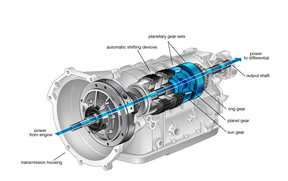
También se conoce como transmisión automática, transmisión de n velocidades o automática de convertidor de par, este es el tipo estándar de transmisión automática que se encuentra en la mayoría de los automóviles en estos días. A diferencia de una caja de cambios manual, no utiliza embrague para cambiar de marcha. En cambio, un acoplamiento de fluido hidráulico o un convertidor de par hacen este trabajo. Se conecta a la Unidad de Control Electrónico del motor y permite un control preciso del vehículo.
Es un tipo de transmisión que cambia automáticamente las relaciones de transmisión a medida que el vehículo se mueve. Los beneficios de un AT se centran en brindar a los conductores la libertad de cambiar de marcha manualmente. Otras ventajas incluyen un control del motor suave y preciso. Tenga en cuenta que AT se puede encontrar en muchos vehículos que no son MT.
Los coches automáticos funcionan sin problemas, pero el cambio de marchas no es rápido todo el tiempo, lo que les valió el nombre de «slushbox». Sin embargo, la impresión ha ido cambiando gracias a algunos modelos de transmisión brillantes, como la ZF de 8 velocidades, que se encuentra en muchos coches, desde Jaguars hasta BMW.
Transmisión manual automatizada
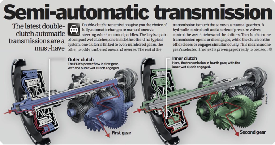
También conocida como transmisión semiautomática (SAT) o cajas de cambios con paletas de cambio, una transmisión semiautomática es un tipo de transmisión automática en la que el conductor realiza cambios de marcha similares a una transmisión manual. Sin embargo, no tiene embrague a diferencia de un MT y utiliza equipos electrónicos como sensores, actuadores y procesadores para simular el cambio manual y hacer que el cambio de marcha sea preciso y suave.
Este tipo de transmisión automática utiliza una configuración normal de embrague y engranaje, pero automatiza la acción mediante el uso de sensores, actuadores, procesadores y sistemas neumáticos.
Los coches con esta transmisión ofrecen un mejor rendimiento en las carreteras. No se recomiendan para conducir en ciudad porque los motores se sienten entrecortados al acelerar con fuerza.
Transmisión continuamente variable (CVT)
Una transmisión continuamente variable o CVT es técnicamente otro tipo de transmisión automática. Sin embargo, no utiliza engranajes mecánicos a diferencia de un AT y, en su lugar, utiliza correas o poleas para permitir cambios de marcha fluidos en función de las raciones y de la velocidad del motor. El diseño compacto y la aceleración continua son algunas de las ventajas de una CVT, mientras que la sensación y el costo del motor son algunas de sus desventajas.
Permite cambios de marcha fluidos con numerosas gamas de relaciones y facilita que el motor gire a las RPM (velocidad) máximas.
Existen dos tipos más de CVT. La CVT hidrostática utiliza motores hidrostáticos y bombas de desplazamiento variable para transferir potencia al motor. Por otro lado, las CVT Toroidales utilizan discos y rodillos de potencia para este fin. La transmisión permite que el motor funcione con la máxima eficiencia con una aceleración fluida. Es bueno para ahorrar combustible y la reparación y el mantenimiento no son costosos. Sin embargo, el motor genera mucho ruido al acelerar y bajo carga. Muchos modelos utilizan esta caja de cambios y algunos de los favoritos del público son Chevrolet Spark, Ford C-Max, Nissan Sentra y más.
Transmisión de doble embrague (DCT)
Otro tipo de transmisión automática es el sistema de transmisión de doble embrague o DCT. También conocida como transmisión de doble embrague o transmisión de doble embrague, no tiene un convertidor de par e implica principalmente el uso de dos embragues separados para conjuntos de marchas pares e impares, lo que permite un cambio fluido a marchas más altas y más bajas. Tampoco tiene pedal de embrague y, en su lugar, una computadora acciona ambos embragues. Por tanto, ofrece la facilidad de un AT con el rendimiento de un MT.
Es un híbrido de transmisión automática y manual. No hay convertidor de par en DCT. Utilizará dos ejes separados para cambiar de marcha, uno para las marchas impares y otro para las pares. Ambos ejes tienen su propio embrague.
Puedes cambiar a una marcha más alta o más baja en una fracción de segundo y la transición de automático a manual también es perfecta. Sin embargo, las cajas de cambios DCT no pueden escapar a las quejas de embragues ruidosos, chirridos y cambios bruscos.
Caja de cambios de cambio directo (DSG)
Es uno de los tipos de transmisión automática que funciona igual que una caja de cambios manual. Sin embargo, es diferente de la operación manual en el sentido de que utiliza un convertidor de par en lugar de un pedal de embrague, tiene la opción de cambio automático y no permite que el conductor tenga control total sobre las marchas.
Una transmisión Tiptronic le da al conductor la opción de conducir en modo automático o manual. Introducida por Porsche en los años 90 y adoptada poco después por otros fabricantes, este tipo de transmisión automática no tiene embrague pero, cuando se utiliza en modo manual, permite la selección directa de marchas ascendentes y descendentes mediante levas detrás del volante o utilizando la propia palanca de cambios. . Cuando se utiliza en modo automático, la computadora realiza el cambio de marcha.
Lo único de esta unidad es que tiene la opción de anular el modo automático. Significa que puede conducir su automóvil en modo automático y además poder cambiar al modo manual cuando sea necesario, como subir una colina o bajar por una carretera empinada.
Los automóviles que utilizan esta unidad tienen una característica de seguridad incorporada para que cualquier error del conductor no provoque daños en la caja de cambios. Varios fabricantes utilizan este tipo de transmisión automática, pero se vio por primera vez en el Porsche 911 (en 1990) y luego fue adoptada por BMW y Chrysler.
It is an engine in which combustion of fuel take place inside the engine. When the fuel burns inside the engine cylinder, it generates a high temperature and pressure. This high-pressure force is exerted on the piston (A device which free to moves inside the cylinder and transmit the pressure force to crank by use of connecting rod), which used to rotate the wheels of vehicle. In these engines we can use only gases and high volatile fuel like petrol, diesel. These engines are generally used in automobile industries, generation of electric power etc.
Advantages of I.C. engine
It has overall high efficiency over E.C. engine. These engines are compact and required less space. Initial cost of I.C. engine is lower than E.C. engine. This engine easily starts in cold because of it uses high volatile fuel.
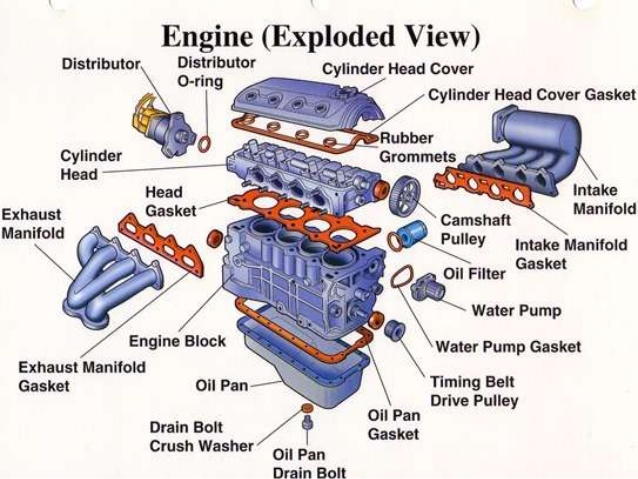
COMPONENTS OF IC ENGINE
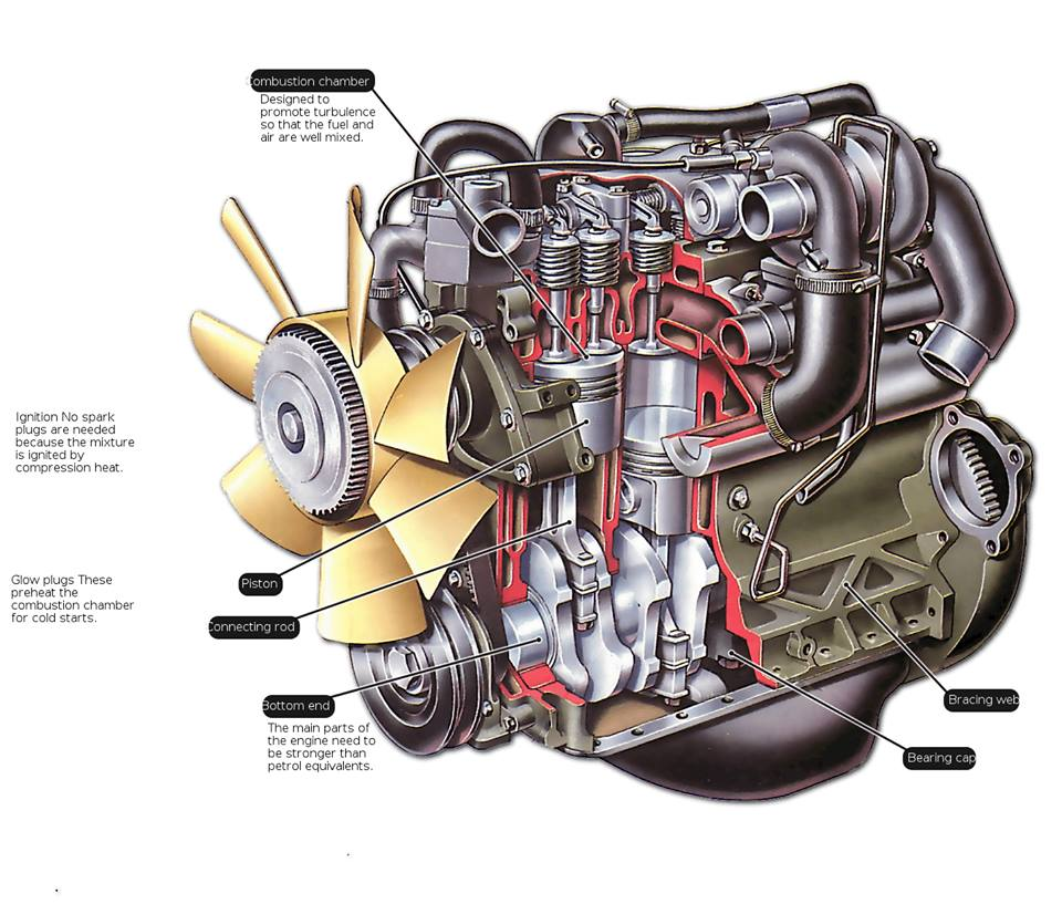
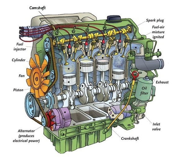
1. Cylinder block Cylinder is the main body of IC engine. Cylinder is a part in which the intake of fuel, compression of fuel and burning of fuel take place. The main function of cylinder is to guide the piston. It is in direct contact with the products of combustion so it must be cooled. For cooling of cylinder, a water jacket (for liquid cooling used in most of cars) or fin (for air cooling used in most of bikes) are situated at the outer side of cylinder. At the upper end of cylinder, cylinder head and at the bottom end crank case is bolted. The upper side of cylinder is consisting a combustion chamber where fuel burns. To handle all this pressure and temperature generated by combustion of fuel, cylinder material should have high compressive strength. So it is made by high grade cast iron. It is made by casting and usually cast in one piece.
2. Cylinder head The top end of the engine cylinder is closed by means of removable cylinder head. There are two holes or ports at the cylinder head, one for intake of fuel and other for exhaust. Both the intake and exhaust ports are closed by the two valves known as inlet and exhaust valve. The inlet valve, exhaust valve, spark plug, injector etc. are bolted on the cylinder head. The main function of cylinder head is to seal the cylinder block and not to permit entry and exit of gases on cover head valve engine. Cylinder head is usually made by cast iron or aluminum. It is made by casting or forging and usually in one piece.
3. Piston A piston is fitted to each cylinder as a face to receive gas pressure and transmit the thrust to the connecting rod. It is a prime mover in the engine. The main function of piston is to give tight seal to the cylinder through bore and slide freely inside the cylinder. Piston should be light and sufficient strong to handle gas pressure generated by combustion of fuel. So the piston is made by aluminum alloy and sometimes it is made by cast iron because light alloy piston expands more than cast iron so they need more clearances to the bore.
4. Piston rings A piston must be a fairly loose fit in the cylinder so it can move freely inside the cylinder. If the piston is too tight fit, it would expand as it got hot and might stick tight in the cylinder and if it is too loose it would leaks the vapor pressure. To provide a good sealing fit and less friction resistance between the piston and cylinder, pistons are equipped with piston rings. These rings are fitted in grooves which have been cut in the piston. They are split at one end so they can expand or slipped over the end of piston. A small two stroke engine has two piston rings to provide good sealing but a four-stroke engine has an extra ring which is known as oil ring. Piston rings are made of cast iron of fine grain and high elastic material which is not affected by the working heat. Sometimes it is made by alloy spring steel.
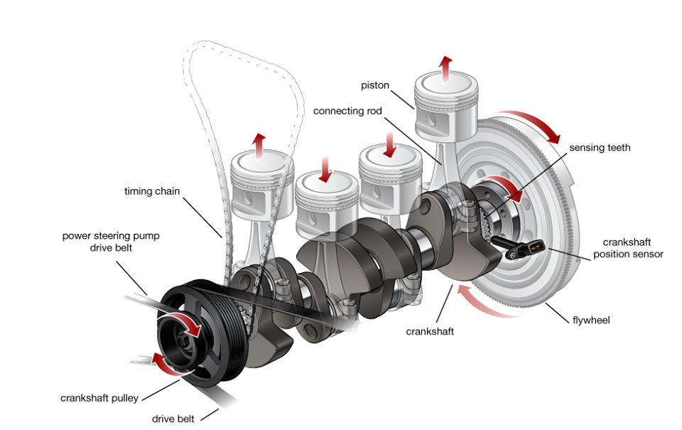
5. Connecting rod Connecting rod connects the piston to crankshaft and transmits the motion and thrust of piston to crankshaft. It converts the reciprocating motion of the piston into rotary motion of crankshaft. There are two end of connecting rod; one is known as big end and other as small end. Big end is connected to the crankshaft and the small end is connected to the piston by use of piston pin. The connecting rods are made of nickel, chrome, and chrome vanadium steels. For small engines the material may be aluminum.
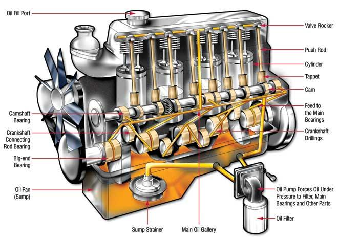
6. Crankshaft The crankshaft of an internal combustion engine receives the efforts or thrust supplied by piston to the connecting rod and converts the reciprocating motion of piston into rotary motion of crankshaft. The crankshaft mounts in bearing so it can rotate freely. The shape and size of crankshaft depends on the number and arrangement of cylinders. It is usually made by steel forging, but some makers use special types of cast-iron such as spheroidal graphitic or nickel alloy castings which are cheaper to produce and have good service life.
7. Engine bearing Everywhere there is rotary action in the engine, bearings are needed. Bearings are used to support the moving parts. The crankshaft is supported by bearing. The connecting rod big end is attached to the crank pin on the crank of the crankshaft by a bearing. A piston pin at the small end is used to attach the rod to the piston is also rides in bearings. The main function of bearings is to reduce friction between these moving parts. In an IC engine sliding and rolling types of bearing used. The sliding type bearing which are sometime called bush is use to attach the connecting rod to the piston and crankshaft. They are split in order to permit their assembly into the engine. The rolling and ball bearing is used to support crankshaft so it can rotate freely. The typical bearing half is made of steel or bronze back to which a lining of relatively soft bearing material is applied.
8. Crankcase The main body of the engine at which the cylinder are attached and which contains the crankshaft and crankshaft bearing is called crankcase. It serves as the lubricating system too and sometime it is called oil sump. All the oil for lubrication is placed in it.
9. Valves To control the inlet and exhaust of internal combustion engine, valves are used. The number of valves in an engine depends on the number of cylinders. Two valves are used for each cylinder one for inlet of air-fuel mixture inside the cylinder and other for exhaust of combustion gases. The valves are fitted in the port at the cylinder head by use of strong spring. This spring keep them closed. Both valves usually open inwards.
10. Spark plug It is used in spark ignition engine. The main function of a spark plug is to conduct a high potential from the ignition system into the combustion chamber to ignite the compressed air fuel mixture. It is fitted on cylinder head. The spark plug consists of a metal shell having two electrodes which are insulated from each other with an air gap. When high potential current supply to spark plug it jumping from the supply electrode and produces the necessary spark.
11. Injector Injector is usually used in compression ignition engine. It sprays the fuel into combustion chamber at the end of compression stroke. It is fitted on cylinder head.
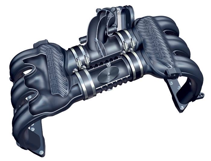
12. Manifold The main function of manifold is to supply the air fuel mixture and collects the exhaust gases equally from all cylinder. In an internal combustion engine two manifold are used, one for intake and other for exhaust. They are usually made by aluminum alloy.
13. Camshaft Camshaft is used in IC engine to control the opening and closing of valves at proper timing. For proper engine output inlet valve should open at the end of exhaust stroke and closed at the end of intake stroke. So to regulate its timing, a cam is use which is oval in shape and it exerts a pressure on the valve to open and release to close. It is drive by the timing belt which drives by crankshaft. It is placed at the top or at the bottom of cylinder.
14. Gudgeon pin or piston pin These are hardened steel parallel spindles fitted through the piston bosses and the small end bushes or eyes to allow the connecting rods to swivel. It connects the piston to connecting rod. It is made hollow for lightness.
15. Pushrod Pushrod is used when the camshaft is situated at the bottom end of cylinder. It carries the camshaft motion to the valves which are situated at the cylinder head.
16. Flywheel A flywheel is secured on the crankshaft. The main function of flywheel is to rotate the shaft during preparatory stroke. It also makes crankshaft rotation more uniform.
TYPES OF I.C ENGINE
I.C. engine is widely used in automobile industries so it is also known as automobile engine. An automobile engine may be classified in many manners.
According to number of stroke:
1. Two stroke engine In a two stroke engine a piston moves one time up and down inside the cylinder and complete one crankshaft revolution during single time of fuel injection. This type of engine has high torque compare to four stroke engine. These are generally used in scooters, pumping sets etc.
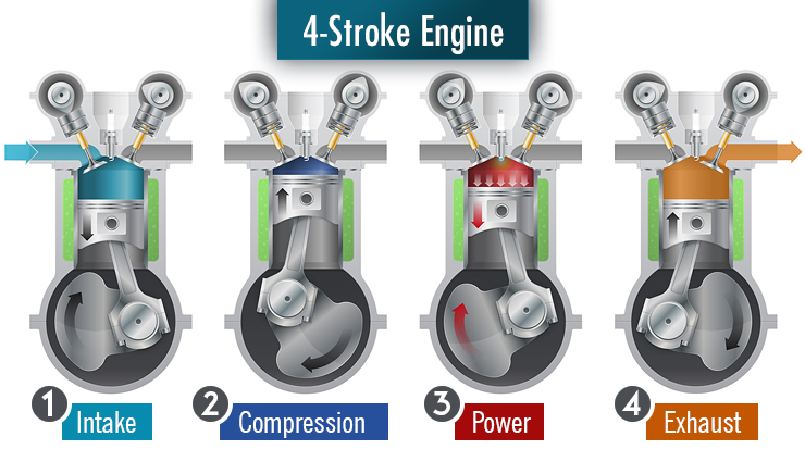
2. Four stroke engine In a four stroke engine piston moves two times up and down inside the cylinder and complete two crankshaft revolutions during single time of fuel burn. This type of engines has high average compare to two stroke engine. These are generally used in bikes, cars, truck etc.
According to design of engine:
1. Reciprocating engine (piston engine) In reciprocating engine the pressure force generate by combustion of fuel exerted on a piston (A device which free to move in reciprocation inside the cylinder). The piston starts reciprocating motion (too and fro motion). This reciprocating motion converts into rotary motion by use of crank shaft. So the crank shaft starts to rotate and make rotate the wheels of the vehicle. These are generally used in all automobile.
2. Rotary engine (Wankel engine) In rotary engine there is a rotor which frees to rotate. The pressure force generated by burning of fuel is exerted on this rotor so the rotor rotate and starts to rotate the wheels of vehicle. This engine is developed by Wankel in 1957. This engine is not used in automobile in present days.
According to fuel used:
1. Diesel engine These engines use diesel as the fuel. These are used in trucks, buses, cars etc.
2. Petrol engine These engines use petrol as the fuel. These are used in bikes, sport cars, luxury cars etc.
3. Gas engine These engines use CNG and LPG as the fuel. These are used in some light motor vehicles.
According to method of ignition:
1. Compression ignition engine In these types of engines, there is no extra equipment to ignite the fuel. In these engines burning of fuel starts due to temperature rise during compression of air. So it is known as compression ignition engine.
2. Spark ignition engine In these types of engines, ignition of fuel start by a spark, generated inside the cylinder by some extra equipment (Spark Plug). So it is known as spark ignition engine.
According to number of cylinder:
1. Single cylinder engine In this type of engines have only one cylinder and one piston connected to the crank shaft.
2. Multi-cylinder engine In this type of engines have more than one cylinder and piston connected to the crank shaft
According to arrangement of cylinder:
1. In-line engine In this type of engines, cylinders are positioned in a straight line one behind the other along the length of the crankshaft.
2. V-type engine An engine with two cylinder banks inclined at an angle to each other and with one crankshaft known as V-type engine.
3. Opposed cylinder engine An engine with two cylinders banks opposite to each other on a single crankshaft (V-type engine with 180o angle between banks).
4. W-type engine An engine same as V-type engine except with three banks of cylinders on the same crankshaft known as W-type engine.
5. Opposite piston engine In this type of engine there are two pistons in each cylinder with the combustion chamber in the center between the pistons. In this engine, a single combustion process causes two power strokes, at the same time.
6. Radial engine It is an engine with pistons positioned in circular plane around the central crankshaft. The connecting rods of pistons are connected to a master rod which, in turn, connected to the crankshaft.
According to air intake process:
1. Naturally aspirated In this types of engine intake of air into cylinder occur by the atmospheric pressure.
2. Supercharged engine In this type of engine air intake pressure is increased by the compressor driven by the engine crankshaft.
3. Turbocharged engine In this type of engine intake air pressure is increase by use of a turbine compressor driven by the exhaust gases of burning fuel.
ENGINE TERMINOLOGY
1. Top dead center (T.D.C.) In a reciprocating engine the piston moves to and fro motion in the cylinder. When the piston moves upper direction in the cylinder, a point at which the piston comes to rest or change its direction known as top dead center. It is situated at top end of cylinder.
2. Bottom dead center (B.D.C.) When the piston moves in downward direction, a point at which the piston come to rest or change its direction known as bottom dead center. It is situated in bottom side of cylinder.
3. Stroke (L) The maximum distance travel by the piston in single direction is known as stroke. It is the distance between top dead center and bottom dead center.
4. Bore (b) The inner diameter of cylinder known as bore of cylinder.
5. Maximum or total volume of cylinder (Vtotal) It is the volume of cylinder when the piston is at bottom dead center. Generally, it is measure in centimeter cube (c.c.).
6. Minimum or clearance volume of cylinder (Vclearance) It is the volume of cylinder when the piston is at top dead center.
7. Swept or displace volume (Vswept) It is the volume which swept by the piston. The difference between total volume and clearance volume is known as swept volume.
Swept volume = Total volume – Clearance volume
8. Compression ratio The ratio of maximum volume to minimum volume of cylinder is known as the compression ratio. It is 8 to 12 for spark ignition engine and 12 to 24 for compression ignition engine.
Compression ratio = Total volume / Clearance volume
9. Ignition delay It is the time interval between the ignition start (spark plug start in S.I. engine and inject fuel in C.I. engine) and the actual combustion starts.
10. Stroke bore ratio Stroke bore ratio is the ratio of bore (diameter of cylinder) to length of stroke. It is generally equal to one for small engine and less than one for large engine.
Stroke bore ratio = inner diameter of cylinder / length of stroke
11. Mean effective pressure The average pressure acting upon the piston is known as mean effective pressure. It is given by the ratio of the work done by the engine to the total volume of engine.
Mean effective pressure = Work done by engine / Total volume of cylinder
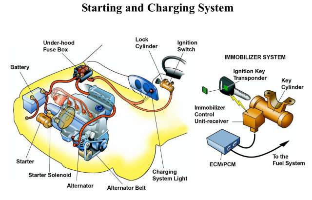
CHARGING SYSTEM: COMPONENTS, FUNCTIONS, WORKING PRINCIPLE AND DIAGNOSIS TIPS
The vehicle is equipped with many electrical devices to drive safely and comfortably. The vehicle requires electricity not only while driving but also while it stops.
Therefore, the vehicle has a battery for a power supply and a charging system to generate electricity by the engine running. The charging system supplies electricity to all the electrical devices and charges the battery.
The Charging system is an important part of the electrical system. It provides electrical current for the lights, the radio, the heater, the engines electrical systems, and other electrical accessories. It also maintains the batteries in a charged state, recharging them as necessary.
The charging system has three main components: the alternator, the voltage regulator, and the batteries.
The alternator generates electrical power to run accessories and to recharge the batteries. It is normally driven by a belt located off the crankshaft. Mechanical energy from the crankshaft is converted by the alternator into electrical energy for the batteries and accessories. The voltage regulator acts as an electrical traffic cop to control the alternator output. It senses when the batteries need recharging, or when the vehicles electrical needs increase and adjust the alternator’s output accordingly.
The batteries are a reservoir of chemical electrical power. Their primary purpose is to crank the engine. They also supply power to vehicle accessories when the electrical load is too great for the alternator alone.
Three-phase alternating current
(1) When a magnet rotates within a coil, a voltage will be created between both ends of the coil. This will give rise to an alternating current. (2) The relation between the current generated in the coil and the position of the magnet is as shown in the figure. The largest amount of current is generated when the N and S poles of the magnet are closest to the coil. However, the current flows in the opposite direction with each half-turn of the magnet. Current that forms a sine wave in this manner is called “single-phase alternating current”.
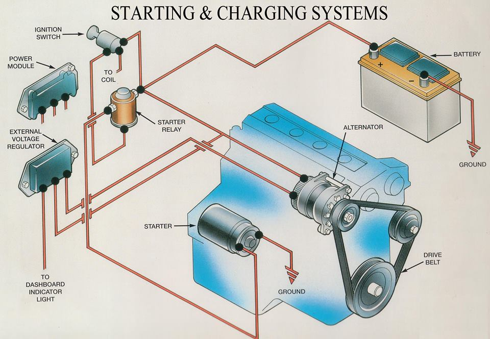
COMPONENTS AND FUNCTIONS
In general, the components of the charging system are composed of alternators and regulators. However, the charging system needs to add some additional components so that the electricity generated can be supplied to the battery and to all electrical loads safely and precisely. The component, consisting of;
1. Battery
The function of the battery is as a storage of electrical energy. Like a warehouse, the battery will store all the electrical energy generated by the alternator and then this stored electricity is removed when necessary.
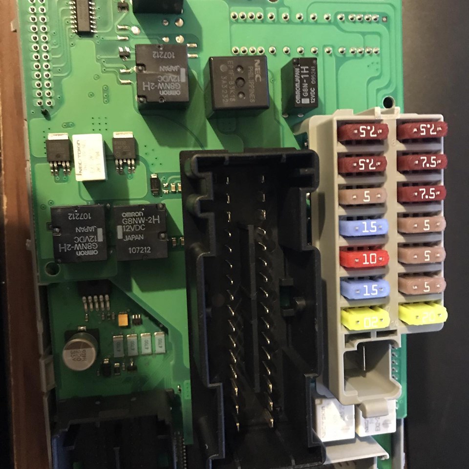
2. Fuse and Fusible links
Fuse and fusible links have different functions even though have the same shape. The fusible link can be called as the main fuse which is placed near the battery positive terminal. The function of this fuse is to protect the entire electrical system of the car from excessive currents. Generally, the fusible link has a capacity of up to more than 60 Ampere.
While the function of the fuse is as the safety of a series of specific electrical wiring, in conventional charging system there are two fuses with the same capacity (it’s about 10-15 Ampere). A fuse is used as a voltage regulator fuse and another fuse is used to secure the CHG and Voltage relay.
3. CHG Lights
CHG lamp or commonly also called “charging warning light” is an indicator light to indicate the present failure of the charging system. When the ignition key ON then this light will light up normally, as well as when the engine life of this lamp should turn on, if it is dead then it could mean the charging system failure.
4. Ignition key
The ignition key works as a switch. The charging system will be activated automatically when the engine is running, but to generate a magnetic field on the rotor coil must be done by a switch.
The ignition switch is used as a switch to connect and disconnect power (positive battery current) from battery to rotor coil. When the ignition key is ON, then the electricity from the battery to the coil rotor will be connected. However, when the ignition key is turned OFF then the power supply will be cut off. So it is not possible the alternator generates electricity when the ignition key is OFF even the engine crankshaft rotates.
5. Regulator
The function of the regulator is to regulate the voltage generated by the alternator. Why should it be there? because the voltage generated by the alternator depends on the engine’s RPM. This means that if the engine RPM is low, the alternator voltage is also low, but if the engine RPM is high then the alternator voltage is also high.
The regulator will be used to keep the voltage generated by the alternator not exceeding 14 volts even if the engine run in high RPM. This voltage setting aims to protect the electrical components of the vehicle to prevents over-voltage.
There are two types of regulators, namely type or conventional type and type of IC. The point type/conventional uses two coils to adjust the alternator output voltage. While the IC Regulator uses an IC circuit (Integrated Circuit) to regulate the output voltage.
6. Altenator
The function of the alternator is to convert a partial engine’s rotating energy into electricity. The alternator input comes from the engine pulley connected through a V belt, the rotation of the rotor will cause the intersection of the magnetic force line with the stator coil so that the electrons flow on the stator coil.
The electricity in the stator coil is not directly connected to the battery, but it must pass through the diode bridge to rectify the current. This is done because the current in the stator coil is AC (Alternate Current).
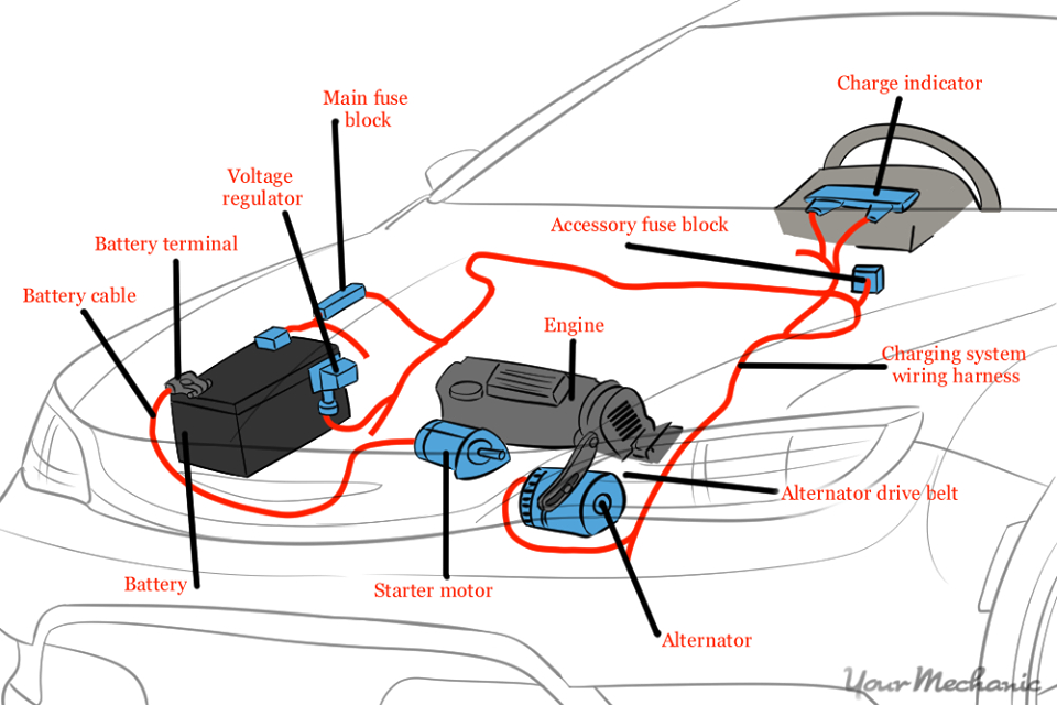
7. Charging Wire
The function of the charging wire is to connect every component of the charging system, there are at least two types of wires: standard wire and B + wire. The standard wire has a small diameter like the car’s electrical wiring in general, the function of this wire is connecting each terminal on the entire charging system.
While the B + wire has a larger diameter than the standard wire and almost matches the stater wire. The function of this wire is to connect the terminal B alternator with Battery.
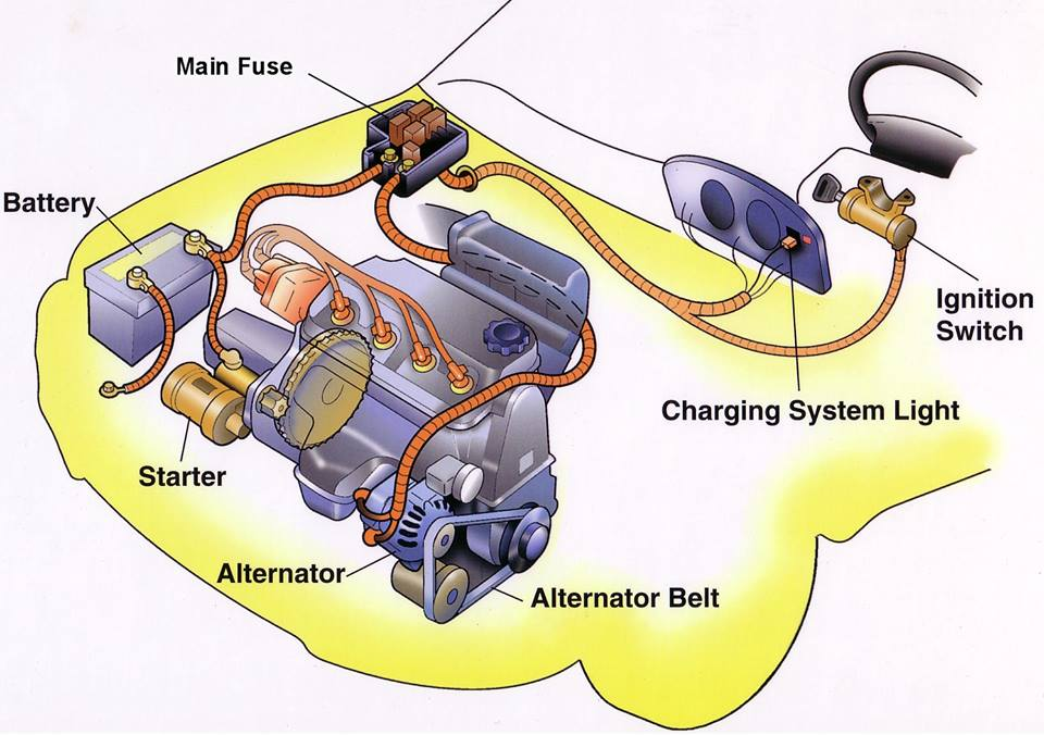
WORKING PRINCIPLE
The flow of electricity in the charging system
Electricity in each position of the ignition switch.
Ignition switch ACC or LOCK
Ignition switch ON (when the engine is not running)
When the ignition switch is in the ON position, current flows from the battery to the alternator. The reason for this is as follows. The alternator generally used for the vehicle generates electricity by rotating the magnet. The magnet is not the permanent magnet but the electromagnet that generates magnetic force by flowing electricity inside. Therefore, it is necessary to supply electricity to the alternator before starting the engine to prepare for generating electricity.
Ignition switch ON (when the engine is running)
FUNCTIONS OF ALTERNATOR
The alternator plays a major role in the charging system. The alternator has three functions of generating electricity, rectifying current and regulating voltage.
(1) Generation Transmitting the engine revolution to the pulley via the v-ribbed belt turns the electromagnetic rotor, generating alternating current in the stator coil.
(2) Rectification Since the electricity generated in the stator coil is alternating current, this cannot be used for the DC electric devices installed on the vehicle. To use the alternating current, the rectifier is used to rectify the alternating current into direct current.
(3) Regulation of voltage IC regulator regulates the generated voltage to make the voltage constant even when the alternator speed or the amount of current flowing into the electric devices change.
CHARGING SYSTEM DIAGNOSIS
The following general information has been assembled as a guide for charging system diagnosis. Refer to the appropriate Original Equipment Manufacturer’s service manual for specific information pertaining to charging system diagnostic procedures and safety precautions for your vehicle.
BENCH TESTING
If an alternator test bench is available, follow the procedures found in the bench tester’s instruction manual to conduct an alternator performance test. This test will determine if the alternator output is within its performance specification, preventing unnecessary alternator replacement. If the alternator output is within specification during bench testing, resolve problems in the remainder of the vehicle’s charging circuit and other electrical circuits that may affect charging circuit performance. Refer to the appropriate vehicle manufacturer’s service manual for the procedures and circuit schematics necessary to identify and correct additional charging circuit problems. If the test bench results show the alternator’s output performance to be out of specification, replace the alternator. Follow the vehicle manufacturer’s recommended procedures to inspect the remainder of the charging circuit and other electrical circuits that may affect charging circuit performance.
NOTE: If the bench test identifies the regulator as defective, it may be possible to replace the regulator (internal or external) and return the alternator to service. If the regulator is replaced and the alternator returned to service, follow the vehicle manufacturer’s recommended procedures to inspect the remainder of the charging system and other electrical circuits that may affect charging circuit performance. Whether or not a test bench was used to determine the condition of the alternator, the following Helpful Tips have been assembled to help isolate conditions that may affect charging circuit performance.
HELPFUL TIPS
1. What is the condition of the battery? • A visual inspection and a performance test of the battery must always be performed before inspecting the charging system. The battery must be fully charged (12.6 volts) and the battery cables, terminals, and casein good, clean condition. This includes the frame and body grounds as well (refer to Battery Visual Inspection and Performance Testing).
2. Does a charge lamp, amperage (amp) gauge or voltmeter indicate a charging system problem?
Charge Lamp:
• Ignition ON engine not running – The charge lamp should illuminate. • Ignition ON engine running – The charge lamp should illuminate briefly then turn OFF. • Weak Battery – A weak battery can cause the charge lamp to illuminate during high amperage draw. • Low Idle – A low idle can cause the charge lamp to illuminate dimly. • Poor Wiring – Corroded, broken, loose or frayed wires/ connections could cause the charge lamp to illuminate during idle. • Open Charge Lamp – Some charging systems will not properly operate if the charge lamp bulb fails.
Amp Gauge:
• Ignition ON engine not running – The amp gauge should read zero or slightly below. • Ignition ON engine running – The amp meter should display a current output above zero. It will display a different level of charge depending on what electrical circuits are operating. A negative charge indicates the battery is discharging more quickly than the charging system can supply current. • Wires and connectors – Corroded, broken, loose or frayed wires/connections could cause zero or erratic readings on the gauge.
Voltmeter:
• Ignition ON and engine not running – Gauge readings should be between 12.0 and 12.6 volts with the ignition ON and the engine not running. Readings below 12 volts could indicate insufficient charging, low battery, corroded, broken, loose or frayed wires/connections. • Ignition ON and engine running – Gauge readings should be between 13.0 and 14.5 volts with the ignition ON and the engine running. A reading exceeding 14.5 volts could indicate a bad battery, failed regulator or poor wire connections. A reading below 13.2 volts could indicate a failed alternator or corroded, broken, loose or frayed wires/connections.
3. Are any fuses open?
• Check the fuses in all the fuse box(es). An open fuse indicates circuit problem(s) that may have an effect on the charging circuit. Check the owner’s manual or the manufacturer’s service manual for the location of each fuse box.
4. Is the fusible link(s) open?
• There may be several fusible links controlling battery voltage to the vehicle’s electrical circuits. If a fusible link is open, the supply voltage will be completely lost to all electrical systems or to the electric circuit(s) that the open fusible link controls. Check the owner’s manual or the manufacturer’s service manual for the location of each fusible link.
5. Is the alternator’s drive belt tension within specification?
• Too loose – If the drive belt is too loose, it will slip around the pulley causing the alternator to charge irregularly or not at all. • Too tight – If the drive belt is too tight, internal bearing damage will cause premature alternator failure.
6. Are the alternator’s drive belt in good condition and the proper size?
• Worn or too narrow – If the alternator’s drive belt is worn or too narrow, it will slip around the pulley, causing the alternator to charge irregularly or not at all. • New drive belt – The life of a new alternator drive belt is approximately 10 minutes. It is important to check and adjust the belt’s tension to the “used” specification after the initial 10 minutes of operation.
7. Has the vehicle been modified or additional equipment installed after it left the factory?
• Accessories – Non-factory accessories such as phones, computer outlets, televisions, refrigerators, stereo equipment or lights, among others, can overburden alternator performance and cause premature failure. • Improper accessory installation – Improper accessory installation procedures can cause charging problems. Some of these problems may include poor ground points, loose connections or improper wiring.
8. Has any work been performed on the vehicle?
• Electrical ground points – Check the ground circuits between the battery and engine and also from the vehicle body to the frame for high resistance. Many times when a vehicle has been repaired, the ground point(s) are disturbed or not re-secured properly. • Multiple electrical grounds – With multiple ground vehicles, each electrical circuit is assigned to one or more ground points. The poor ground at one ground point may cause feedback through another ground point causing unusual circuit activity.
Diesel engines tend to emit higher Nitrogen Oxide (NOx) which is harmful to humans. This is because of high temperatures in the engine cylinders because of the higher compression ratio. To control and decrease the NOx, manufacturers employ ‘Exhaust Gas Recirculation’ technology in engines.
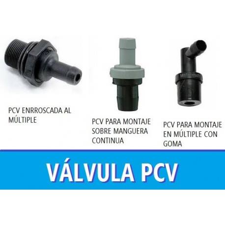
The term EGR stands for Exhaust Gas Recirculation. It is a part of modern-day diesel engine vehicles which helps to decrease the Nitrogen Oxide (NOx) emissions. Exhaust Gas Recirculation is the technique used for reducing the nitrogen oxide in both the internal combustion diesel engines as well as petrol engines.
WORKING PRINCIPLE
The exhaust gas added to the fuel, oxygen, and combustion products increases the specific heat capacity of the cylinder contents, which lowers the adiabatic flame temperature.
In a typical automotive spark-ignited (SI) engine, 5% to 15% of the exhaust gas is routed back to the intake as EGR. The maximum quantity is limited by the need of the mixture to sustain a continuous flame front during the combustion event; excessive EGR in poorly set up applications can cause misfires and partial burns. Although EGR does measurably slow combustion, this can largely be compensated for by advancing spark timing. The impact of EGR on engine efficiency largely depends on the specific engine design, and sometimes leads to a compromise between efficiency and NOx emissions. A properly operating EGR can theoretically increase the efficiency of gasoline engines via several mechanisms:
• Reduced throttling losses.
The addition of inert exhaust gas into the intake system means that for given power output, the throttle plate must be opened further, resulting in increased inlet manifold pressure and reduced throttling losses.
• Reduced heat rejection.
Lowered peak combustion temperatures not only reduces NOx formation, but it also reduces the loss of thermal energy to combustion chamber surfaces, leaving more available for conversion to mechanical work during the expansion stroke.
• Reduced chemical dissociation.
The lower peak temperatures result in more of the released energy remaining as sensible energy near TDC (Top Dead-Center), rather than being bound up (early in the expansion stroke) in the dissociation of combustion products. This effect is minor compared to the first two.
EGR is typically not employed at high loads because it would reduce peak power output. This is because it reduces the intake charge density. EGR is also omitted at idle (low-speed, zero loads) because it would cause unstable combustion, resulting in rough idle.
Since the EGR system recirculates a portion of exhaust gases, over time the valve can become clogged with carbon deposits that prevent it from operating properly. Clogged EGR valves can sometimes be cleaned, but replacement is necessary if the valve is faulty.
DESIGN
A vacuum controlled EGR valve regulates the number of exhaust gases admitted into the cylinders. It consists of a spring-loaded vacuum diaphragm. It links to a metered valve which controls the passage of the exhaust gases. Ported vacuum from a calibrated signal port located above the throttle valve connects to the EGR vacuum chamber.
At idling, the EGR valve is in the closed position because of the spring pressure and lower ported vacuum. The engineers designed it so because if the exhaust gases recirculate at the idling, then it would cause rough/erratic idling. Upon opening of the throttle applies the ported vacuum and gradually opens the tapered valve. This causes the exhaust gas to flow into the intake manifold.
However, when the throttle opens fully, there is no vacuum in the intake manifold. So, it closes the tapered valve and stops the exhaust gases from entering the intake manifold.
BENEFITS
The Exhaust Gas Recirculation system recirculates a part of the exhaust gas back into the engine cylinders through the combustion chamber. The logic behind the EGR system is very simple. The exhaust gas is hotter than the fresh air sucked by the engine. So, the exhaust gas significantly reduces the contents of the cylinder for combustion. Because of the absence of oxygen (O2), the exhaust gases have nothing to burn as they contain neither fuel nor oxygen particles.
Thus, it results in lower heat discharge and cylinder temperatures. It reduces the formation of nitrogen oxide (NO2) as well. The dormant exhaust gas present in the cylinder also limits the peak temperatures. It also reduces the loss that arises because of throttling in petrol engines while improving the engine life by reducing the cylinder temperatures. The three-stage catalytic converter further reduces the NOx to acceptable levels.
LIMITATIONS
The engineers designed the EGR system in such a way that it recirculates the exhaust gases only when the engine forms the Nitrogen Oxide (NOx). Thus, the EGR system DOES NOT affect the ‘Full-Load’ operation.
The Exhaust Gas Recirculation system also has a thermal control valve in the vacuum line which prevents the operation of EGR at lower engine temperatures. This system is useful especially in the diesel engines where the catalytic converter cannot stimulate the chemical reduction due to high oxygen contents. So, the NOx emission remains the same in such conditions.}
Las mariposas en un motor tienen la función de controlar la cantidad de aire que circula hacia los cilindros de éste mediante un circuito de colectores de admisión, por lo que son muy importantes.
En los motores más antiguos, solo se necesitaba una mariposa para controlar el aire que succionaban los pistones y, dependiendo del tipo de motor, podían ser una por cada cilindro.
En la actualidad, existen mecanismos que controlan mucho mejor la entrada del aire hacia los cilindros por lo que el sistema de admisión varía en función del tipo de motor y del sistema de admisión variable, ya que con éste se pretende aprovechar al máximo la dinámica del aire para llenar mejor los cilindros y aumentar el rendimiento de los motores.
Existen mariposas controladas por aire y mariposas controladas eléctricamente, pero la función es la misma. Como es lógico, las controladas eléctricamente son más caras. También están las principales que van controladas mecánicamente mediante cable.
¿Qué sucede cuando se estropean las mariposas?
De normal, los fallos provocados por averías de mariposa se deben a la falta de aire en los cilindros, lo que en su mayoría de casos va a provocar una pérdida de potencia y aumento de consumo.
Cuando esto sucede, se pueden apreciar “tirones” en marcha, sobre todo cuando necesitamos potencia y si la que falla es la mariposa principal, el motor podría no arrancar ya que “estrangulamos” totalmente la entrada de aire.
Otra forma de notar que las mariposas fallan es que el motor tiraría humo negro ya que la combustión no la haría completa al faltarle aire.
* 4 stroke engine completes 2 rotations of the crankshaft after completing one cycle. * Power is produced once every 4 strokes of the piston. * Engine design is a bit complicated due to valve mechanism which is operated through gear & chain mechanism. * No need of adding oil or lubricant to fuel. * Top side of the piston is flat. * Mixture remains only in the combustion chamber. * 4 stroke engines are heavier. * 4 stroke engines make less noise.
2 STROKE ENGINES
* 2 stroke engine completes 1 rotation of crankshaft after completing one cycle. * Power is produced once during 2 strokes of the piston. * 2 stroke engine has ports which make its design simpler. * Addition of oil is required. * A bump or protuberance may be needed on the top side of the piston. * Air-fuel mixture enters through inlet port & travels to combustion chamber passing through the crankcase. * 2 stroke engines are lighter comparatively. * 2 stroke engines are louder comparatively.
ADVANTAGE AND DISADVANTAGES
4 STROKE ENGINE:-
ADVANTAGES
1. More torque:- In general, 4 stroke engines always make extra torque than 2 stroke engine at low RPM. Although 2 stroked ones give higher torque at higher RPM it has a lot to do with fuel efficiency.
2. More fuel efficiency:- 4 stroke engines have greater fuel efficiency than 2 stroke ones because fuel is consumed once every 4 strokes.
3. Less pollution:- As power is generated once every 4 strokes & also as no oil or lubricant is added to the fuel; 4 stroke engine produces less pollution.
4. More durability:- We all know that more the engine runs, quicker it wears out. 2 stroke engines are designed for high RPM. If an engine can go for 10000 rpm’s before it wears out; a 4 stroke engine with 100 rpm will run for 100 minutes than the other 2 stroke engine which has a higher rpm of 500 & will run for only 20 minutes.
5. No extra addition of oil:- Only the moving parts need lubrication intermediately. No extra oil or lubricant is added to fuel.
DISADVANTAGES
1. Complicated design:- A 4 stroke engine has complex valve mechanisms operated & controlled by gears & chain. Also, there are many parts to worry about which makes it harder to troubleshoot.
2. Less powerful:- As power gets delivered once every 2 rotations of the crankshaft(4 strokes), hence 4 stroke is less powerful.
3. Expensive:- A four-stroke engine has much more parts than 2 stroke engine. So they often require repairs which leads to greater expense.
2 STROKE ENGINE:-
ADVANTAGES
1. Simple design & construction:- It doesn’t have valves. It simply has inlet & outlet ports which makes it simpler.
2. More powerful:- In 2 stroke engine, every alternate stroke is power stroke unlike 4 stroked one in which power gets delivered once every 4 strokes. This gives a significant power boost. Also, the acceleration will be higher & power delivery will be uniform due to the same reason.
3. The position doesn’t matter:- 2 stroke engine can work in any position as lubrication is done through the means of fuel (as the fuel passes by through whole cylinder & crankcase).
DISADVANTAGES
1. Less fuel efficiency:- For every alternate power stroke, fuel gets consumed every alternate stroke. This makes the engine less fuel efficient although it results in uniform power delivery.
2. Oil addition could be expensive:- Two-stroke engines require a mix of oil in with the air-fuel mixture to lubricate the crankshaft, connecting rod and cylinder walls. These oils may empty your pockets.
3. More pollution:- 2 stroke engine produces a lot of pollution. The combustion of oil added in the mixture creates a lot of smoke which leads to air pollution.
4. Wastage of fuel:- Sometimes the fresh charge which is going to undergo combustion gets out along with the exhaust gases. This leads to wastage of fuel & also power delivery of the engine gets affected.
5. Improper combustion:- The exhaust gases often get trapped inside the combustion chamber. This makes the fresh charge impure. Therefore maximum power doesn’t get delivered because of improper incomplete combustion.
Clasificación SAE (Society of Automotive Engineers)
Esta clasificación tomó como referencia el grado de viscosidad del lubricante en función a la temperatura la que se somete el motor durante su funcionamiento, por lo que no clasifica a los aceites por su calidad.
La marca de certificación y el símbolo de servicio API identifican la calidad de los aceites de vehículos de gasolina y diesel.
Clasificación
El sello de API también conocido como “STARBURST”, indica que el aceite cumple con la normativa vigente de
protección del motor y con los requisitos de economía de combustible ILSAC.
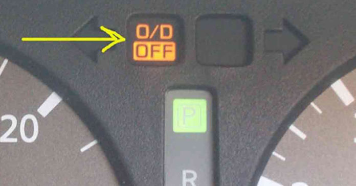
Cuando el aviso de “O/D OFF” esta encendido, quiere decir que el overdrive está apagado; y cuando el aviso está apagado, quiere decir que el overdrive está encendido (lo sé, suena algo confuso pero es solo cuestión de leer lo que dice el tablero)
Overdrive activado o encendido: el indicador “O/D OFF” está apagado
Overdrive desactivado o apagado: el indicador “O/D OFF” está encendido
¿Para qué sirve el overdrive?
Veamos las diferencias, sin overdrive:
El carro dispone de hasta 3 cambios o cajas
Los cambios de caja resultan más largos, es decir el cambio automático de 1a a 2a tarda más, etc
El motor realiza más revoluciones
El motor en funcionamiento presenta más ruido
Hay un mayor consumo de combustible
Al frenar o disminuir la velocidad se hace con frenado de motor
Se pierde inercia, por el punto anterior
Es ideal para cuando se va lento (dentro de la ciudad por ejemplo), cuando hay constantes frenados, cuando se lleva carga, cuando se está en un terreno con pendientes o pantanoso
Con overdrive:
El carro dispone de 4 cambios o más (según la especificación del carro)
Los cambios de caja resultan más cortos, es decir el cambio automático de 1a a 2a tarda menos
El motor realiza menos revoluciones
El motor en funcionamiento presenta menos ruido
Hay un menor consumo de combustible
Al frenar o disminuir la velocidad no se hace con frenado de motor, solo se aplica freno de disco o del que disponga el carro
No se pierde inercia, por el punto anterior
Es ideal para cuando se va rápido (sobre carretera por ejemplo), cuando no se lleva carga
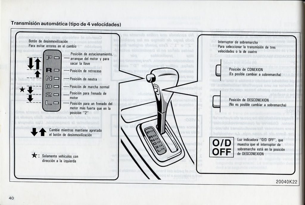
En resumen cuando necesitemos que el carro haga un poco más de esfuerzo, debemos tener el overdrive apagado (aviso encendido de “O/D OFF”), y cuando queramos que haga menos esfuerzo y vaya más rápido debemos activar el overdrive. También hay que tomar en cuenta que para activar el overdrive se puede estar en marcha de 0 a 60 km/hr o un poco más dependiendo del carro que tengamos; y para desactivar el overdrive se puede hacer cuando estemos en marcha a poca velocidad, o cuando el carro no esté en movimiento.
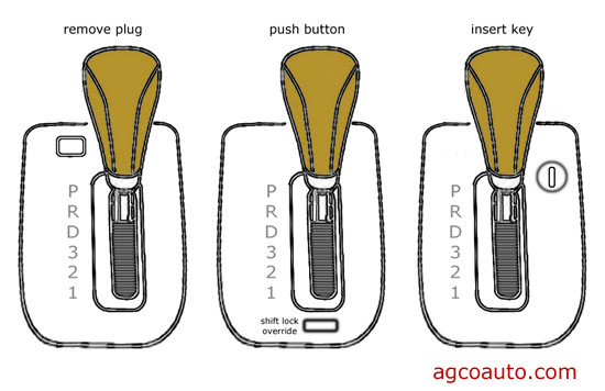
Si tienes un coche automático, te habrás encontrado con el botón Shift Lock muy cerca en de la palanca que utilizas para cambiar entre las diversas posiciones de manejo. Aquí te decimos para qué sirve y cómo te puede ayudar a salir de un apuro.
El botón Shift Lock te puede sacar de un apuro en más de una ocasión
Muchas personas manejan sus autos con transmisión automática sin tener la remota idea de la existencia del botón Shift Lock. Aunque suele estar en una zona visible cerca de la palanca o selector, la mayoría ignora para qué funciona y la forma correcta de utilizarlo.
La incorporación del Shift Lock en los autos de transmisión automática es una necesidad, dado que el control de los cambios no depende del conductor, a diferencia de lo que sucede en un vehículo con una caja manual de velocidades. De esta manera, conocer el funcionamiento del sistema de bloqueo de cambios se convierte en un tema de seguridad.
Cuando nos ponemos detrás del volante de un coche automático, tenemos que presionar un botón ubicado en la palanca de velocidades para moverlo entre las diferentes posiciones, ya se Neutral, Estacionamiento, Drive o Reversa. Lo único que se necesita es tener pisado el freno y presionar el botón para desplazar la palanca a conveniencia, un mecanismo que también evita que se cambie de posición de forma accidental y que termine por dañar la caja de velocidades.
En algunas ocasiones o contratiempos, existe la posibilidad de que la palanca de la transmisión se quede trabada. Aquí es donde resulta de gran utilidad el botón Shift Lock, ya que solo tendremos que seguir una serie de pasos muy sencillos para poder utilizar el auto de nueva cuenta o, dependiendo de la situación, remolcarlo al lugar que nos convenga.
El botón Shift Lock permite “destrabar” la palanca de forma mecánica
Algunos de los escenarios que te obligarían a utilizar Shift Lock sería que te quedaras sin batería en el vehículo en posición de Estacionamiento (P), una de las situaciones más frecuentes que suele dar dolores de cabeza. Por más que se pise el freno para intentar desplazar la palanca a Neutral (N) y así poder mover la unidad, esto no dará resultados hasta que destrabemos el selector de forma mecánica.
De esta manera, el botón Shift Lock permite que se desactive de forma manual el enclavamiento de la posición P y volver a Neutral para permitir el remolque. La palanca puede quedar inmovilizada por otros factores o averías, como puede ser un falso contacto en uno de los interruptores que son presionados por el pedal de freno. Sin importar cuál sea la razón, mediante este botón se podrá cambiar de posición con el vehículo apagado y sin pisar el freno.
Lo primero que tenemos que hacer es colocar el freno de mano y retirar la llave del encendido. Acto seguido, se levanta la tapa del Shift Lock con un desarmador plano, teniendo extremo cuidado de no dañar los acabados. Con la misma llave del vehículo, se presiona la tecla hacia abajo y, al mismo tiempo, intentamos mover la palanca a posición Neutral. Para terminar el trabajo, colocamos la cubierta de plástico, introducimos la llave y presionamos el pedal de freno. Si no se trata de un asunto de batería, podemos intentar encender el motor; en caso contrario, estaremos listos para iniciar con el remolque de la unidad.
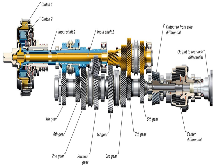
A manual transmission is a house of various components like gears, shafts and various selecting mechanism that is arranged in special fashion to provide appropriate torque and speed ratios to compete with the challenges provided by the different road conditions, the shifting from high torque to high speed and vice-versa is performed manually by symmetrical pushing and pulling of the gear lever by the driver.
The vehicle with MT usually comes with an n-speed manual with or without reverse configuration where ‘n’ denotes the number of speed ratios or shifts for example-Maruti Suzuki swift comes with 5-speed 1-reverse manual transmission.
COMPONENTS OF A MANUAL TRANSMISSION
1. Clutch Pedal: The clutch pedal is a hydraulically controlled piece of gear that disengages the clutch when you depress it.
2. Clutch: This is a system of components which is used to transmit engine torque to the transmission. It consists of a pressure plate, diaphragm spring, clutch disc, throw-out bearing, and other smaller components. The clutch disc is a friction pad which is sandwiched between the flywheel and the pressure plate.
3. Flywheel: As it relates to manual transmissions, the flywheel is the component which delivers engine torque to the clutch disc. This circular mass has a smooth surface which the clutch disc interacts with.
Understanding how a clutch works are fairly important to understanding the transmission overall.
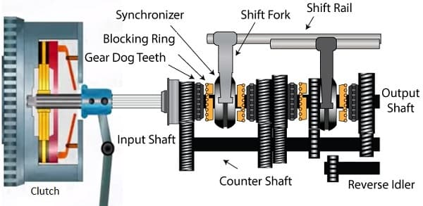
4. Selector Fork This arm is used to move the collars along the output shaft (to select gears) and can be moved using the gear shift.
5. Collar(s) The collar is what is used to select different gears. It slides between gears and can mesh with them. The collar is splined to the output shaft, whereas the gears rotate with the layshaft (and thus are on bearings on the output shaft). By locking the collar with a selected gear, engine torque passes from the layshaft to the output shaft.
6. Synchronisers These are located between the gears and the collar and allow for the collar to engage the gear even if there is a speed differential between the two. Essentially, this aids in matching the speed of the gear and the collar.
7. Shafts There are usually 3 shafts used in a manual transmission those are-
(i) Main-Shaft- It is the shaft that is also called the output shaft and is placed in front of the clutch shaft and in parallel to the lay-shaft. Gears, gear lever along with the meshing devices such as dog clutches and synchromesh devices are mounted over this shaft.
(ii) Lay-shaft or Counter Shaft- It is the shaft used as an intermediate shaft between the clutch shaft and the main shaft, it is usually mounted below and parallel to the main shaft, and act as an engine output carrier from the clutch shaft to the main shaft.
(iii) Clutch-Shaft- It is the shaft that carries the rotational output from the engine’s flywheel to the transmission with the help of clutch that engages and disengages the output from the engine.
8. Gears Various sized gears are used to allow for different wheel speeds. Larger gears will provide more torque but have lower maximum speeds. Smaller gears (with fewer teeth) will provide less torque but will allow the car to travel at a higher speed.
There are mainly 4 types of gears used in the manual gearbox those are-
(i) Spur Gear: Used in old sliding mesh gearbox these types of gears have straight cut teethes.
(ii) Helical Gear: They are the modified version of the latter as they have angular cut teethes.
(iii) Bevel: They are best of all above gears having a conical cross-sectional area with angular cut teethes.
(iv) Idler-gear: It is the small gear used as a reverse gear usually mounted over the layshaft.
TYPES OF MANUAL GEARBOX USED
There are 3 types of manual gearboxes used since the introduction of the transmission that is-
1. Sliding Mesh Gearbox
This is the oldest type of gearbox used. In this type of gearbox shifting occurs by the sliding of gears over the splined main-shaft in order to mesh with the appropriate gear on the lay-shaft whose one gear is in constant mesh with the clutch shaft gear in order to carry rotational motion for the conversion(high torque or high speed)as required by the drive, this gearbox requires special technique for the shifting that is usually known as double-declutching and also the meshing was so noisy and harsh, that gives rise to the development of a new gearbox system. Note-They usually came with the max of 3-speed manual shifts.
2. Constant Mesh Gearbox
This is the modified version of the later which was introduced to over the limitations of the later, in this type all the gears on the main-shaft, lay-shaft and clutch-shaft are in constant mesh with each other and the selection of the appropriate gear is done by the special meshing devices known as dog clutches which slides over the splined main-shaft in order to select the appropriate gear as need by the drive. This system flushes away the double-de-clutching problem and made the drive less noisy as the spur gears of the sliding mesh is replaced with the helical or bevel gears ,but the shifting of gear is still not smooth and also there is a lot of wear and tear of the dog clutches due to the different rotational speed of the shafts while meshing, which leads to the high maintenance. Note – it came with 4 or 5-speed 1-reverse manual shift configuration.
3. Synchromesh Gearbox
This is the latest type of gearbox used from decades as this system overcomes all the limitations provided by the constant mesh gearbox or sliding mesh gearbox and also improves the output capabilities of the manual transmission system, in this type the dog clutches from the constant mesh gearbox is replaced by the synchromesh devices which first bring the main-shaft and lay-shaft at same speed by the frictional contact, then meshing of the appropriate gear occurs which makes the system smooth and also decreases the maintenance of the gearbox, today this system usually comes with 5-speed 1-reverse manual transmission configuration.
Note-it is coming with a 5-speed 1-reverse configuration.
WORKING OF MODERN MANUAL TRANSMISSION
Today almost all the vehicles with a manual transmission on the road are equipped with synchromesh gearbox as it is more reliable, needs less maintenance, and the selection of gear is not complex with This type of gearbox whose working is as follows-
• When the driver presses the clutch pedal in order to shift the gear, the disengagement of the engine flywheel and clutch shaft occurs which lets the driver select appropriate gear according to the need of the drive.
• When the gear lever is pushed or pulled by the driver in order to select the particular gear, the synchromesh device which is attached to the particular link slides towards the selected constantly meshed pair of gears.
• At first, this synchromesh device makes the frictional contact with the selected pair and the shafts in order to bring the rotating shafts at the same speed.
• Then the pair of gears having an appropriate gear ratio has meshed with the synchromesh device in order to obtain output given by the pair of gears, which is then transferred to the main shaft.
• Then this output with appropriate torque or speed is transferred to the final drive when the driver releases the clutch pedal which completes the shifting of gear.
• When it comes to the selection of reverse gear the contact of the synchromesh device is made with the idler gear which in turn reverses the rotation of the main shaft and the drive starts moving in a reverse direction. Note – As constant meshing of gears and Continuous sliding of synchronizing devices is there so constant supply of lubricating oil should be there in order to avoid wear and tear of the components of the manual transmission.
APPLICATION
Specifically, manual transmission covers 52% of the total automobile market which means more than half the vehicle on the roads is equipped with MT.
1. All the heavy vehicles such as trucks, loaders, etc. Are equipped with MT.
2. Almost all the bikes on the road are having a manual gearbox with usually 4 or 5-speed shifts with no reverse.
3. The formula race cars use a manual transmission with quick response shifting mechanism.
4. Almost all commercial cars use MT due to their low cost except high-end cars like Audi, BMW, etc.
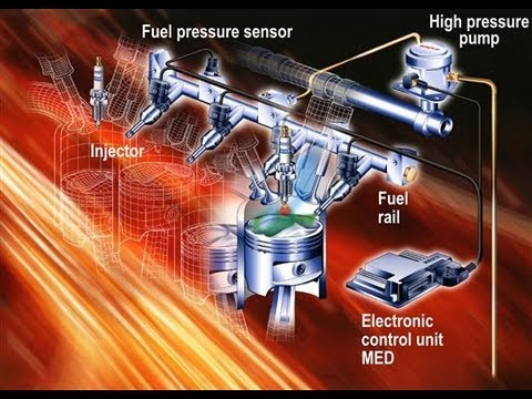
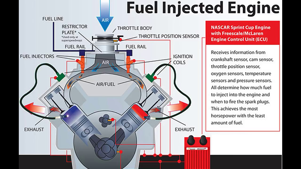
“ Fuel injector is an electronically controlled mechanical device that is responsible for spraying (injecting) the right amount of fuel into the engine so that a suitable air/fuel mixture is created for optimal combustion.”
The technology was created in the early 20th century and implemented on diesel engines first. By the final third of the 20th century, it had also become popular among regular gasoline engines.
The electronic control unit (ECU at engine management system) determines the precise amount and specific timing of required gasoline (petrol) dose for every cycle, by collecting information from various engine sensors. So, the ECU sends a command electrical signal of the correct duration and timing to the fuel injector coil. In that way opens the injector and allows petrol to pass through it into the engine.
The one terminal of the injector coil is directly supplied by 12 volts which are controlled by the ECU, and the other terminal of the injector coil is open. When ECU determined the exact amount of fuel and when to inject it, activates the appropriate injector by switching the other terminal to the ground (mass, i.e. negative pole).
COMPONENTS
The objectives of the fuel injection system are to meter, atomize and distribute the fuel throughout the air mass in the cylinder. At the same time, it must maintain the required air-fuel ratio as per the load and speed demand on the engine.
* Pumping elements:
To move the fuel from the fuel tank to the cylinder.
* Metering elements:
To measure the supply of the fuel at the rate demanded by speed and load conditioning on the engine
* Metering control:
To adjust the rate of the metering elements for change in load and speed of the engine.
* Mixture control:
To adjust the ratio of the fuel and air as demanded by the load and speed.
* Distributing elements:
To divide the metered fuel equally among the cylinder.
* Timing control:
To fix the start and stop of the fuel-air mixing process.
TYPES OF FUEL INJECTORS
1. Top-Feed – Fuel enters from the in the top and exits the bottom.
2. Side-Feed – Fuel enters on the side on the injector fitting inside the fuel rail.
3. Throttle Body Injectors – (TBI) Located directly in the throttle body.
TYPES OF FUEL INJECTION SYSTEMS
1. Single-Point OR Throttle Body Fuel Injection
Also referred to as a single port, this was the earliest type of fuel injection to hit the market. All vehicles have an air intake manifold where clean air first enters the engine. TBFI works by adding the correct amount of fuel to the air before it is distributed to the individual cylinders. The advantage of TBFI is that it’s inexpensive and easy to maintain. If you ever have an issue with your injector, you’ve only got one to replace. Additionally, since this injector has a fairly high flow rate, it’s not as easy to clog up.
Technically, throttle body systems are very robust and require less maintenance. That being said, throttle body injection is rarely used today. The vehicles that still use it are old enough that maintenance will be more of an issue than it would with a newer, lower mileage car.
Another disadvantage to TBFI is the fact that it’s inaccurate. If you let off the accelerator, there will still be a lot of fuel in the air mixture that is being sent to your cylinders. This can result in a slight lag before you decelerate, or in some vehicles, it can result in unburned fuel being sent out through the exhaust. This means that TBFI systems are not nearly as fuel efficient as modern systems.
2. Multiport Injection
Multiport injection simply moved the injectors further down towards the cylinders. Clean air enters the primary manifold and is directed out towards each cylinder. The injector is located at the end of this port, right before it’s sucked through the valve and into your cylinder.
The advantage of this system is that fuel is distributed more accurately, with each cylinder receiving its own spray of fuel. Each injector is smaller and more accurate, offering an improvement in fuel economy. The downside is that all injectors spray at the same time, while the cylinders fire one after the other. This means that you may have leftover fuel in between intake periods, or you may have a cylinder fire before the injector has had a chance to deliver additional fuel.
Multiport systems work great when you are traveling at a consistent speed. But when you are quickly accelerating or removing your foot from the throttle, this design reduces either fuel economy or performance.
3. Sequential Injection
Sequential fuel delivery systems are very similar to multiport systems. That being said, there is one key difference. Sequential fuel delivery is times. Instead of all injectors firing at the same time, they deliver fuel one after the other. The timing is matched to your cylinders, allowing the engine to mix the fuel right before the valve opens to suck it in. This design allows for improved fuel economy and performance.
Because fuel only remains in the port for a short amount of time, sequential injectors tend to last longer and remain cleaner than other systems. Because of these advantages, sequential systems are the most common type of fuel injection in vehicles today.
the one small downside to this platform is that it leaves less room for error. The fuel/air mixture is sucked into the cylinder only moments after the injector opens. If it is dirty, clogged, or unresponsive, your engine will be starved of fuel. Injectors need to be kept at their peak performance, or your vehicle will start to run rough.
4. Direct Injection
If you’ve started to notice the pattern, you can probably guess what direct injection is. In this system, fuel is squirted right into the cylinder, bypassing the air intake altogether. Premium automobile manufacturers like Audi and BMW would have you believe that direct injection is the latest and greatest. With regards to the performance of gasoline vehicles, they’re absolutely right! But this technology is far from new. It’s been used in aircraft engines since the second world war, and diesel vehicles are almost all direct injection because the fuel is so much thicker and heavier.
In diesel engines, direct injection is very robust. Fuel delivery can take a lot of abuse, and maintenance issues are kept to a minimum.
With gasoline engines, direct injection is found almost exclusively in performance vehicles. Because these vehicles operate with very precise parameters, it’s especially important to maintain your fuel delivery system. Although the car will continue to run for a long time when neglected, the performance will quickly decline.
METHODS OF FUEL INJECTION
There are two methods of fuel injection in the compression ignition system
1. Air blast injection 2. Air less or solid injection
1. Air blast injection
This method was originally used in large stationary and marine engines. But now it is obsolete. In this method, the air is first compressed to very high pressure. A blast of this air is then injected carrying the fuel along with it into the cylinders. The rate of fuel injection is controlled by varying the pressure of the air. The high-pressure air requires a multi-stage compressor so as to keep the air bottles charged. The fuel ignites by the high temperature of the air caused by the high compression. The compressor consumes about 10% of the power developed by the engine, decreasing the net output of the engine.
2. Airless or solid injector
In this method, the fuel under high pressure is directly injected into the combustion chamber. It burns due to the heat of compression of the air. This method requires a fuel pump to deliver the fuel at high pressure around 300kg/cm^2. This method is used for all types of small and big diesel engines. It can be divided into two systems
1. Individual pump system: in this system each cylinder has its own individual high-pressure pump and a measuring unit.
2. Common rail system: in this system the fuel is pumped by a multi-cylinder pump into a common rail, the pressure in the rail is controlled by a relief valve. A measured quantity of fuel is supplied to each cylinder from the common rail.
This is all about the fuel injection system. If you have any query regarding this article, ask by commenting. If you like this article, don’t forget to share it on social networks. Subscribe our website for more informative articles. Thanks for reading it.
WORKING PRINCIPLES
The injectors are controlled by the Engine Control Unit (ECU). First, the ECU obtains information about the engine conditions and requirements using different internal sensors. Once the state and requirements of the engine have been determined, the fuel is drawn from the fuel tank, transported through the fuel lines and then pressurized with fuel pumps. Proper pressure is checked by a fuel pressure regulator. In many cases, the fuel is also divided using a fuel rail in order to supply the different cylinders of the engine. Finally, the injectors are ordered to inject the necessary fuel for the combustion.
The exact fuel/air mixture required depends on the engine, the fuel used and the current requirements of the engine (power, fuel economy, exhaust emission levels, etc.)
Otto Cycle is the theoretical thermodynamic cycle which describes the working of a spark ignition engine. This type of spark ignition engines is the most common type of engines used in automobiles. Today we will attempt to study it and understand what comprises of this Otto Cycle.
The Otto cycle is the study of what happens to a mass of gas when it is subjected to changes in pressure, temperature, volume, adding heat and removing heat. The system is the term given to the mass of gas that is subjected to these changes. Otto Cycle also studies the effect of this system on the environment. The effect in question here is the net output or the work generated by the Otto Cycle to move the automobile in which the engine is installed.
The name Otto Cycle comes from the name of the person who has put forward the theory of this system.His name was Dr Nicolas August Otto. The Otto Cycle comprises a top and bottom of the loop process which is called isentropic process. This process is frictionless and adiabatic. And an isochoric process which happens at left and right side of the loop and has the constant volume.
The reason we consider the Otto cycle as a theory is because of its premise that it operates in a completely efficient system where no energy is lost. However, we know that in reality, it is still not possible.
The isentropic process implies that during compression cycle there will be no loss of mechanical energy and considers that no heat will either enter the system or leave it. In theory, heat flows through the left pressurizing process and some of it passes back through the right depressurizing process. The difference of heat here gives the net mechanical work generated.
The Following Are The Four Processes In Otto Cycle-
Process 0-1 :
Also known as the intake stroke
Mass of air at constant pressure is fed into the cylinder/piston
Process 1-2:
Also known as Compression stroke.
In this process, the isentropic compression of the charge happens. This happens due to movement of the cylinder from bottom dead center to top dead center.This is the time when air-fuel mixture is compressed.
Process 2-3 :
This is also known as Ignition phase.
Here the piston for a moment of time rests at the top dead center. There is a little air-fuel mixture present at the top during this process. Heat is then introduced into the system which ignites the air-fuel mixture. Due to this, the volume remains constant whereas the pressure rises.
Process 3-4 :
Also known as Expansion stroke.
The rise in pressure due to ignition causes the piston to move to bottom dead centre.Gases are expanded isentropically and hence the system works on the piston.In simpler terms, the expansion of gases leads to movement of piston here.
Process 4-1 :
Also known as Heat Rejection phase.
The piston comes to rest at bottom dead center for a while. This drops the gas pressure immediately as the heat is removed using a heat sink at the cylinder head. The gas returns to its original state as was in step 1.
Process 1-0 :
Also known as the Exhaust stroke.
The exhaust valve opens in this process as the piston moves from Bottom dead center to top dead center. The remainder gas is expelled and the process again starts from 0-1.
So here we have in theory how an Otto process works.
Como se vio en el vídeo aquí vamos dejar algunos buenos artículos que vamos a estar utilizando a lo largo del vídeo , así que es muy importante que los tengan descargados, y muy atentos con todo lo que se publica, otra cuestión que nos gustaría aclarar es que en los vídeos que vayamos subiendo aquí iremos dejando el material ya que en youtube por temas de copyright podemos ocasionar un altercado, sin mas que decir , esperemos que disfruten el curso, estará muy enfocado a piezas automotrices, con el fin de enfocarnos en esa materia
La barra estabilizadora de la suspensión de un vehículo es una barra de acero con propiedades de naturaleza elástica, que se encuentra fijada en sus extremos a cada soporte de la suspensión de cada lado del mismo eje.
Todo vehículo circulando a velocidad por una curva se ve sometido a una fuerza centrífuga que hace que se incline hacia un costado, que puede generar una sensación de molestia en los ocupantes del vehículo, además de poder existir un peligro real de vuelco del vehículo si la velocidad fuera inadecuadamente excesiva.
Esto es así debido a la fuerza centrífuga que actúa sobre el vehículo, que es de dirección radial y ejerce un empuje sobre el vehículo que tira de él hacia el exterior de la curva.
Esta fuerza genera una transferencia de carga en el vehículo que hace inclinar a la carrocería de tal forma que una parte de la suspensión, la situada en el lado exterior a la curva, se comprima, mientras que la otra parte de la suspensión del vehículo, la situada hacia el interior de la curva, se expanda corriendo el riesgo de despegar la rueda de este lado del pavimento.
Este hecho, es decir, que las ruedas de un lado del vehículo tiendan a subir, mientras que las ruedas del otro lado tiendan a bajar comprimiéndose contra el suelo, va a generar un par de torsión que es absorbido por la barra estabilizadora, impidiendo que la carrocería se incline excesivamente hacia un lado y ejerciendo una resistencia al balanceo del vehículo.
Así, el movimiento vertical hacia arriba de la rueda situada del lado interior de la curva se transmite a la otra rueda del eje a través de la barra estabilizadora, que tiende a bajar la carrocería de ese lado comprimiendo el muelle de la suspensión, de manera que se consigue sumar la acción de los dos muelles, ayudando a mantener la estabilidad del vehículo.
Por ello, la barra estabilizadora se considera un componente elástico de la suspensión dado que actúa en parte también como muelle, especialmente cuando actúa sobre la rueda del lado del eje que tiende a subir.
Este mismo efecto se produce, no sólo cuando el vehículo toma una curva, sino cuando por ejemplo, una de las ruedas encuentra un bache o cualquier obstáculo, creando, al bajar o subir la rueda, un par de torsión en la barra que hace que la carrocería se mantenga en posición horizontal. De esta forma, como se ha dicho, se consigue sumar la acción de los dos muelles.
Por tanto, la barra estabilizadora de la suspensión de un vehículo trabaja a torsión, compensando los esfuerzos generados de una rueda sobre la otra del eje mediante una transferencia de peso de la rueda que se comprime hacia la rueda del lado que tiende a elevarse, aumentando así su adherencia.
De este modo, se evita que el muelle de un lado de la suspensión se comprima excesivamente, mientras que el otro muelle se expanda, pudiendo hacer perder el contacto de la rueda con el piso.
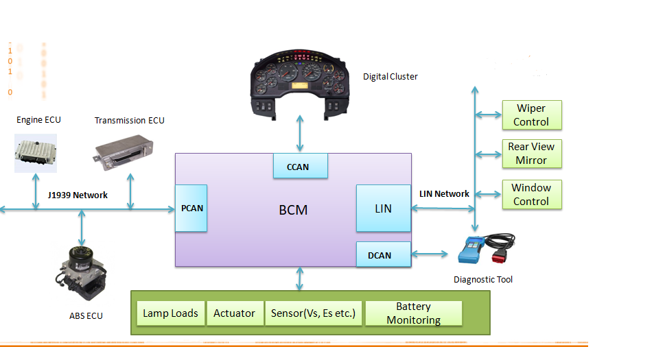
El #BCM es una Computadora o mejor dicho es un modulo, Body Control Module o modulo de control de carroceria, generalmente ese modulo incluye la alarma, controla seguros, y muchas funciones como luces, limpia brizas , elementos de seguridad y confort del auto inclusive hasta inmobilizador.
Puede variar la configuración de este conforme al fabricante, hay muchos vehículos que utilizan como traductor al BMC para comunicarse con otros módulos, esto se refiere a que si el BMC presenta daños podemos tener problemas de fallo de comunicación, activación o desactivación de módulos y funciones del vehículo que facilitan la conducción y el confort de este.
El BCM es el módulo principal de la configuración central del vehículo.
Control de energía
La función de control de energía está integrada en el BCM.
El control de energía permite alimentar con tensión los distintos módulos de forma eficaz según las condiciones existentes. Para ello se utilizan distintos modos.
Según el estado de funcionamiento del vehículo, se utilizan cuatro modos de conducción distintos:
•Modo de producción •Modo de transporte •Modo normal •Modo de colisión
El modo de producción está activo durante la producción del vehículo. En este modo se reduce la alimentación de tensión desconectando varios relés. Cuando el vehículo sale de producción, se desactiva el modo de producción y se activa el modo de transporte.
El modo de transporte está activado en el trayecto del punto de producción al Taller Autorizado. El vehículo se puede conducir sin que esto afecte a la seguridad de conducción.
Algunos módulos, p. ej., sistemas eléctricos (p. ej., sistema antirrobo, reloj y mando a distancia) se desactivan.
De esta forma queda garantizado que el nivel de carga de la batería sea suficiente cuando se entrega el vehículo al cliente.
El modo de transporte debe ser desactivado en el Taller Autorizado. Para ello es necesario, con encendido desconectado, pisar el freno cinco veces y pulsar el interruptor de las luces de emergencia dos veces antes de que transcurran 10 segundos.
Al desactivar el modo de transporte, el BCM pasa automáticamente al modo normal.
El modo normal garantiza el funcionamiento completo de todos los sistemas eléctricos.
El modo de colisión se activa en cuanto el RCM (módulo de control del sistema de seguridad pasivo) registra una colisión de fuerza suficiente.
Con ello se llevan a cabo las siguientes funciones: •El vehículo se desbloquea de forma centralizada si estaba bloqueado en el momento de la colisión. •Las luces de emergencia se activan. •La bomba de combustible se desactiva. •El calefactor adicional de combustible
Las causas por las cueles llegan a fallar los BCM son variadas pero las más generales son
Mal voltaje de batería
Cortos circuitos
Humedad
Corrosión
Software defectuoso
Para realizar programaciones en el BCM es indispensable disponer de una interfaz J2534 que es el módem que nos permitirá hacer el enlace entre el fabricante y nuestro módulo para repararlo, también es importante contar con software de agencia o dealer de la marca para poder hacer el enlace por lo que el uso de una PC o laptop será vital para el proceso.
Las reparaciones y programaciones que se le pueden hacer a este módulo es Reiniciar módulo o reflasheo, es decir iniciar desde cero el software del BCM para que pueda trabajar
Actualización de software : Este se realiza cuando el fabricante indica en una carta de diagnóstico por ejemplo que alguna falla en el sistema sólo se va a poder solucionar actualizando el software
Reemplazo de la unidad por cortos o por golpes que haya sufrido
Realizar operaciones con inmobilizador o sistema de robo
Todo lo anterior se debe de manejar con responsabilidad y cuidado es decir realizar reparaciones con repuestos originales, un diagnóstico utilizando datos en vivo en el scaner y cartas de diagnostico que nos permitan dar con la solución del BCM. Este punto es importante ya que los trabajos en BCM son costosos por lo que un trabajo preciso será una buena recomendación a otro cliente y un crecimiento del centro de servicio
El análisis de elementos finitos (FEA) consiste en el modelado de productos y sistemas en un entorno virtual, con el objetivo de encontrar y resolver posibles problemas estructurales o de rendimiento (o problemas ya existentes). El FEA es la aplicación práctica del método de elementos finitos (FEM), que utilizan los ingenieros y científicos para modelar matemáticamente y resolver numéricamente complejos problemas estructurales, de fluidos y multifísica. El software de FEA se puede utilizar en una amplia gama de sectores pero habitualmente se emplea en el sector de la aeronáutica, la biomecánica y la automoción.
Un modelo de elementos finitos (FE) consta de un sistema de puntos, denominados «nodos», que dibujan la forma del diseño. Conectados a estos nodos se encuentran los propios elementos finitos, que conforman la malla de elementos finitos y que contienen las propiedades estructurales y de material del modelo que definen cómo responderá este ante determinadas condiciones. La densidad de la malla de elementos finitos puede variar a lo largo del material, en función del cambio anticipado en los niveles de tensión de un área determinada. Las regiones que experimentan cambios importantes en la tensión suelen requerir una densidad de malla más elevada que aquellas que experimentan pocas variaciones en la tensión o incluso ninguna. Entre los puntos de interés se encuentran los puntos de fractura de un material probado previamente, las curvas, las esquinas, los detalles complejos y las áreas de tensión elevada.
ESTE FILTRO RECIBE OTROS NOMBRES TALES COMO FILTRO DE POLEN, FILTRO DEL HABITÁCULO Y FILTRO DE INTERIOR Y NO HAY QUE CONFUNDIRLO CON EL FILTRO DE AIRE PUES UNO ES PARA EL MOTOR Y EL OTRO PARA LOS PASAJEROS.
Este filtro, que puede parecer que simplemente es un elemento más para el confort de los pasajeros, es también un elemento de seguridad activa en el caso de conductores alérgicos.
Se trata de un filtro cuya finalidad es la de depurar el aire que entra en el habitáculo de los ocupantes, reteniendo polvo, hollín y sobretodo polen y otras partículas en suspensión. El material del que está fabricado es muy denso (bastante más que el del filtro de aire del motor) lo que le permite retener partículas mucho más pequeñas, del orden de los 0.0030 mm.
Aunque el intervalo de sustitución de estos filtros viene dado por el fabricante, es conveniente cambiarlos por periodos no superiores a los 15.000 Kms o un año(reduciendo estos si los trayectos se realizan por caminos polvorientos o similares) siendo estos intervalos de sustitución especialmente recomendables para el caso de ocupantes alérgicos, asmáticos, o personas mayores. Así mismo es conveniente que estos cambios se realicen al comienzo de la primavera pues es cuando el polen hace su presencia
La disposición de cilindros opuestos, también conocida como motor bóxer, no es tan popular pero todavía se puede encontrar y cuenta con muchos seguidores. En este tipo de mecánica encontramos que los cilindros se colocan enfrentados en un ángulo de 180º. Esta disposición permite que la altura total del bloque se reduzca considerablemente (aunque la anchura sigue siendo notable) y se consiga un centro de gravedad bajo.
En la actualidad son solamente dos marcas las que apuestan por los motores bóxer. Subaru lleva más de medio siglo con estas mecánicas y se usa tanto en gasolina como diésel que van desde 114 CV del 1.6 atmosférico del Subaru XV hasta los 300 CV del 2.5 turboalimentado que equipa el WRX STI. En Porsche también se ha apostado por los bóxer, antes con mecánicas atmosféricas y ahora utilizando la turboalimentación.
A lo largo de la historia ha habido otros bóxer conocidos como el dos cilindros del Citroën 2CV o los de doce cilindros de Ferrari.
Si notas cualquiera de las siguientes fallas es probable que requieras reemplazar la valvula PCV de tu auto:
1. Humo blanco en el escape de tu motor 2. Filtro de aire y/o ductos de aire contaminados por aceite 3. Fallas de ralentí en el motor (variación de rpms) 4. Fugas de aceite en retenes o empaques 5. Códigos de falla relacionados con el cuerpo de aceleración, el sistema IMRC, sensor MAF e IAT.
Humo blanco en el escape:
Cuando la válvula PCV se daña y queda atascada en posición abierta permite que el aceite del motor viaje por el ducto que la conecta hasta las mangueras de la admisión del motor contaminando el filtro del aire, ductos, cuerpo de aceleración, control IMRC, etc.
Cuando el aceite llega a la cámara de combustión se quema junto con la mezcla de aire y gasolina provocando el humo blanco.
Filtro de aire contaminado:
Como vimos en el punto anterior, al atascarse en posición abierta el filtro del aire queda empapado en aceite perdiendo toda posibilidad de filtrar el polvo que entra por el ducto de admisión hacia el motor.
Fallas de ralentí:
Una vez contaminados los sensores en los ductos de admisión como son el sensor MAF, IAT, Cuerpo de aceleración e IMRC el motor puede tener fallas en la aceleración, apagarse al hacer un alto o simplemente dejar de acelerar.
Fugas en empaques y retenes:
Cuando la válvula PCV se atasca en posición cerrada, los gases generados por la combustión y vapores del aceite generan tanta presión que empiezan a dañar los empaques y retenes del motor hasta dañarlos.
El motor empezará a mancharse en su exterior permitiendo dañar más componentes o simplemente quedarse sin aceite.
Tenemos en dos imágenes atajos que te podrán ayudar para hacer mas rápido y eficaz tu trabajo , es muy importante que al principio los tengamos a la mano ya que con esto podríamos reducir minutos vitales para el desarrollo de piezas, ensambles y simulaciones,